Page is loading ...

Wall/window
fan range
GX6
Installation and
maintenance instructions
Retain for future reference
®
GB
F
D
NL
I
a
NO
GR

GB
This appliance is intended for
connection to fixed wiring.
Check that the electrical rating shown
on the appliance matches the mains
supply.
WARNING:THIS APPLIANCE MUST
BE EARTHED.
All installations must be supervised
by a qualified electrician.
Installation and wiring must conform
to current IEE regulations (UK), local
or appropriate regulations
(other countries).
If you have any queries before
installing these products or after they
have been installed, call the
Xpelair Technical Hotline +44 (0) 8709
000430. Our engineers are there to
help you during normal office
hours (UK only) and may be faxed at
all other times +44 (0) 8709 000530.
Customers outside the UK please
contact your local Xpelair distributor,
details of which are available
from the UK office.
The GX6 models have the following
features:
● Window / wall / panel / roof mounting
options.
● For remote switch operation.
● Single speed extract operation.
● Trickle ventilation setting.
● Integral pull cord operation.
● Single speed extract operation.
● Trickle ventilation setting.
● Integral pull cord operation.
● Integral timer facility.
● Single speed extract operation.
● Trickle ventilation setting.
● For remote switch operation.
● Integral timer facility.
● Single speed operation.
● Trickle ventilation setting.
● For remote switch operation.
● Integral humidistat / timer facility.
● Single speed operation.
● Trickle ventilation setting.
● For remote switch operation.
● Integral pull cord operation.
● Integral humidistat / timer facility.
● Two speed operation.
● Trickle ventilation setting.
● Remote switch operation.
● Single speed extract operation.
● Solenoid operated back draught
shutters, for instant opening and
closing.
● Trickle ventilation setting.
● For remote switch operation.
● Single speed extract operation.
● Trickle ventilation setting.
● IP25 ingress protection.
● A double pole isolating switch with a
minimum contact gap of 3mm (wall or
ceiling mounted).
● If metal switch boxes are used,
earthing regulations must be followed.
● The GX6, GXC6, GXC6T and GXS6
require suitably rated 3-core cable
(see “Installing switches and cables”
section).
● The GX6 (IP25) require suitably rated
circular 3-core cable with a diameter
not less than 5.5mm (see “Installing
switches and cables” section).
● The GX6T, GX6HT and GX6HT2
require suitably rated 4 or 5 core
cable (see “Installing switches and
cables” section).
● The GX6T, GX6HT and GX6HT2
requires a wall or ceiling mounted “on
/off’ switch with built-in indicator
light. For external boost/triggering,
two switches are required.
● 6mm blade large screwdriver, 3mm
blade electrician’s screwdriver and
No.1 & 2 Pozidriv screwdrivers.
● A single glazed window with a
minimum glass thickness of 4mm or a
double glazed unit with a pre-
prepared sealed hole.
● Masonry drill, hammer & chisel (or
core drill equipment, if available).
● Mortar (to make good the hole).
● Wall kit WK6/300 (available from
Xpelair) for walls up to 300mm (12”)
thick or WK6/450 (available from
Xpelair) for walls up to 450mm (18”)
thick.
Xpelair GX6, GX6 (IP25), GXC6,
GXC6T, GX6HT, GX6HT2 & GXS6
Installation and Operating Instructions
PLEASE LEAVE THIS LEAFLET WITH THE FAN, FOR THE BENEFIT
OF THE USER.
Installing the fan
Description
GX6
GXC6
GXC6T
GX6T
GX6HT
GX6HT2
GXS6
GX6 (IP25)
What the installer will need
If window mounting the fan, you
will also need:
If wall mounting the fan, you will
also need:
Where to locate the fan
● 4 mounting fasteners (use fasteners
suitable for wall type. Recommended
screw size for standard brick - No.8 x
38mm Pan Head).
● Locate it as high as possible.
●
At least 145mm from edge of the wall/
window frame to the hole centre (see
Fig. A.).
● As far as possible from and opposite
to the main source of air replacement
to ensure airflow across the room
(eg, Opposite an internal doorway).
●
Near the source of steam or odours
.
● Not where ambient temperatures
are likely to exceed 50 degrees C.
● If installed in a kitchen, fans must
not be mounted immediately above
a cooker hob or eye level grill.
● If installing in a room containing a
fuel burning device, which has a
non balanced flue, it is the
installers responsibility to ensure
that there is enough replacement
air to prevent fumes being drawn
down the flue when the fan is
operating up to maximum extract.
Refer to Building Regulations for
specific requirements. Exhaust air
must not be discharged into a flue
used for exhausting fumes from
appliances supplied with energy
other than electric.
Requirements of all authorities
concerned must be observed for
exhaust air discharge and intake
flow rates.
● When intended for use in possible
chemical corrosive atmospheres,
consult our technical service
department. (For overseas markets
contact your local Xpelair
Distributor).
● This electrical product, if installed
in a shower room or bathroom,
must be situated so that it cannot
be touched by persons making use
of the bath or shower.
1. Check that there are no buried
pipes or cables (eg. electricity, gas,
water) behind the switch location
(in the wall or above the ceiling).
2. Lay in the cable from the isolating
switch to the fan location via the on/
off switch (see Fig.E1), SW1 (see
Fig.E2.) and external boost SW1 (see
Fig.E3) if required.
3. Lay in the cable from the isolating
switch to the point of connection to
the mains supply.
WARNING: DO NOT MAKE ANY
CONNECTIONS TO THE ELEC-
TRICAL SUPPLY AT THIS STAGE.
4. Install the isolating switch and the on/
off switch (see Fig.E1), SW1 (see
Fig.E2) and external boost SW2
(see Fig.E3) if required.
5. Make all connections within the
isolating switch and the on/off switch
if required.
Note: When installed in a bathroom
all switches must be of a pull cord
type and must be situated so that
they cannot be touched by persons
making use of the bath or shower.
Installing the switches and
cables

These models are permanently
connected to the supply and
operation is controlled by a remote
switch.
They should be directly wired to the
supply through an approved 10A wall
mounted surface switch with
at least 3mm clearance between
contacts.
If working above ground level,
appropriate safety precautions must
be observed.
WARNING: EYE PROTECTION MUST
BE WORN DURING ALL DRILLING
AND CHISELLING OPERATIONS.
1. Check there are no buried pipes
or cables in the wall or obstructions
on the outside (eg: electricity,
gas, water).
2. Ensure that the centre of the hole
is located at least 145mm from the
edges of the wall.
3. Mark on the centre of the duct hole.
4. Use this centre to draw a circle to
suit the wall duct (203mm diameter
for a WK6/300 or WK6/450).
5a.Use as directed by the core drill
manufacturer.
5b. Drill a centre hole right through the
wall.
5. Cut the hole. Do not cut right
through the wall (the recommended
method is to drill a series of holes,
close together, around the edge of
the cutting line and remove the brick
between the holes with a chisel).
7. Go outside and cut a hole in the
outer wall, repeating the process
described above.
8. Fit the ducting. Ensuring that the
duct slopes down away from the fan
to allow drainage of any incoming
rain water to the outside.
9. Make good the hole. Allow for mortar
to set before continuing with the
installation.
Obtain a ready cut pane with a correctly
located hole 184mm diameter. (See Fig.A).
1. For window mounting, use the two
short ladder strips supplied with the
fan.
For Wall mounting, use the longer
strips supplied with the wall kit
WK6/300 or WK6/450.
2. Secure the two ladder strips to the
outer grille by positioning them over
the hook moulding and snapping
into position.
3.
Ensure after fitting the hook moulding
that the gasket is in the correct
position. (See Fig.B).
4. Insert the two screw covers in the
two fixing holes in the outer grille.
If working above ground floor level,
appropriate safety precautions must
be observed.
Remove the Back Draught Shutter/Grille
Assembly, by pressing the release
catches located on the sides of the unit
with a 6mm screwdriver or coin, whilst
pulling the grille forward.
1. Hold up the outer grille to the
outside of the wall or window so that
the hole in the outer grille is aligned
with the hole in the wall or window.
2. If wiring from the rear, remove the
fans terminal cover and rear entry
knockout. Feed the cable through
the top cable entry.
2b. If wiring from above, remove fans
terminal cover and feed the cable
through the top cable entry.
2c. For GX6 (IP25) only, wiring from
above, remove fan’s terminal cover.
Pierce the cable entry grommet with
a No. 1 screwdriver and feed the
cable through the top cable entry via
the grommet. DO NOT REMOVE
THE GROMMET.
3. Hold the fan assembly to the inside
of the wall or window and guide the
ladder strips from the outer
grille through the slots in the fan
assembly.
4. Insert the slotted screws into the
pockets around the ladder strip slots.
5. Tighten the screws carefully to make
a good seal. Do not over tighten the
screws.
6. Trim the ladder strips back to the
required length, if necessary remove
any sharp edges.
1. Hold the outer grille up to the
outside of the wall so that the hole in
the outer grille is aligned with the
hole in the wall.
2. Mark the positions of the fixing holes
in the top right and bottom left
corners.
3. Drill the holes and insert anchor
fixings to suit the wall.
4. Screw the outer grille securely in
place and fit screw caps in place. Do
not over tighten screws.
5. Insert the two screw covers in the
two fixing holes in the outer grille.
6a. If wiring from the rear, remove the
fans terminal cover, and rear entry
knockout. Feed the cable through the
knockout.
6b. If wiring from above, remove the fans
terminal cover and feed the cable
through the top cable entry.
6c. For GX6 (IP25) only, wiring from
above, remove fan’s terminal cover.
Pierce the cable entry grommet with
a no. 1 screwdriver and feed the
cable through the top cable entry via
the grommet. DO NOT REMOVE
THE GROMMET.
7. Hold the fan assembly to the inside
of the wall so that the spigot is
inserted into the wall duct.
8. Mark the position of the two fixing
holes in the top left and bottom right
corners.
9. Remove the fan assembly, drill the
holes and insert anchor fixings
appropriate to the type of wall.
10. Reposition the cable and fan
assembly as before, and screw
securely in place. Do not over
tighten screws.
Note: For particularly difficult
installations, it is possible to secure the
fan with a combination of screw and
ladder strip fixings.
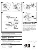
1. Wire the switch cable into the
terminal connections shown:
● Fig.E1 for GX6 / GXC6 / GXC6T /
GXS6 / GX6 (IP25).
● Fig.E2 for GX6T / GX6HT.
● Fig.E3 for GXHT2.
2. If the fan is wired from above,
ensure the outer sheath of cable is
retained in the labyrinth (see Fig.C).
3. Refit and secure terminal cover.
4. Refit the back draught shutter/grille
assembly by sliding the grille back
over the release catches, the
catches will locate and secure the
grille.
5. Switch off the mains electricity
supply and remove fuses.
6. Connect the cable from the isolation
switch to the electrical supply wiring.
7. Replace the fuses and switch on the
mains electrical supply.
For fixed wiring circuits the
protective fuse for the appliances
must not exceed 5A.
Note: If using an external boost switch
for the GX6HT2 (see Fig.E3), cut off the
pull cord after ensuring that it is
in the “off” position. This switch must be
marked with suitable markings to
indicate speed control.
● These fans are single speed, except
the GX6HT2 which is two speed, and
all are non reversible (extract only).
● The shutters have a time delay of up
to 1 minute on opening and up to 3
minutes on closing. Activated by
operation of the switch, the delay
ensures quiet operation (except
GXC6 and GXS6 models).
For Australia Only: WARNING – Children should
not play with the appliance.Young children and
the infirm should be supervised.
● The fan is operated by a remote
switch.
● The fan is operated by an integral pull
cord.
● To switch on, pull down the cord and
then release it.
● Repeat to switch off.
● The fan is operated by an integral pull
cord.
● To switch on, pull down the cord and
then release it.
● Repeat to switch off.
● The integral timer provides an
adjustable overrun period after the
fan has been switched off.
Preparing the hole
Preparing the Fan for
installation
If fixing with ladder strips
If installing in a window
For Australia only
If installing in a wall
If core drill equipment is available
If core drill equipment is not
available
Mounting the fan in the hole
Fig. C
If using screw fixings
Wire the electrical connection
Operating the Fan
GX6
GXC6
GXC6T

● The fan is operated by a remote
switch.
The fan indicator light shows when it
is switched on.
● An integral timer provides an
adjustable overrun period after the
fan is switched off.
Condensation operation
● The fan operates automatically if the
relative humidity is above the set
level.
● The integral timer provides an
adjustable overrun period after the
relative humidity level has fallen.
Switched operation
● A manual operation remote switch
starts the fan. The fan indicator light
shows when it is switched on.
● The integral timer provides an
adjustable overrun period after the
fan has been switched off.
Condensation operation
● The fan operates automatically at low
speed if the relative humidity rises
above the set level.
● The integral timer provides an
adjustable overrun period after the
fan has been switched off.
Boost operation
● The integral pull cord switches the fan
on to run at high speed. The fan
indicator light shows when high
speed has been selected.
● A remote switch may be used as an
alternative to the pull cord. If this is
used, cut off the pull cord, after
ensuring that the pull cord switch is in
the “off” position.
● This fan is operated by a remote
switch.
● This fan is operated by a remote
switch.
Before making any adjustments,
isolate the fan completely from the
mains electricity supply.
Adjusting the timer overrun
The overrun timer is factory preset at
approximately 20 minutes. The time is
adjustable between approximately
2 to 20 minutes.
1. Remove the back draught shutter/
grille assembly (see “Mounting the
fan in the hole” section).
2. Turn the adjuster marked “T” anti-
clockwise to reduce the timer overrun
(see Fig.H).
3.
Turn the adjuster clockwise to increase
the timer overrun (see Fig.H).
4. Replace the back draught shutter/
grille assembly (see “Mounting the
fan in the hole” section).
Adjusting the humidistat setting
The internal humidity sensor is factory
set at approximately 70%. The level is
adjustable between approximately
50% and 90% relative humidity.
Remove the back draught shutter/grille
assembly (see “Mounting the fan in the
hole” section).
Turn the adjuster marked “H” anti-
clockwise to decrease the relative
humidity level of the room (see Fig. 1).
Turn the adjuster clockwise to increase
the relative humidity level of the room
(see Fig.l).
Replace the back draught shutter/grille
assembly (see “Mounting the fan in the
hole” section).
Trickle ventilation is equivalent to that
provided by an airbrick or similar device.
1. Remove the back draught shutter/
grille assembly (see “Mounting the
fan in the hole” section).
2. HOLD THE SHUTTER VANES FULLY
OPEN.
3. Push down firmly on the trickle vent
catch until it clicks into position then
release the shutter vanes. (See
Fig.F item 6).
4. Pull the trickle vent catch towards you
until it clicks into position.
5. Refit the back draught shutter/grille
assembly, see “Mounting the fan in
the hole” section, ensuring that the
actuator lever is in the “fully down”
position.
A QUALIFIED ELECTRICIAN MUST
CARRY OUT ALL CLEANING.
NOTE: THE FAN WILL CONTINUE TO
OPERATE WITH THE INNER GRILLE
REMOVED HENCE IT MUST BE
ISOLATED COMPLETELY FROM THE
MAINS BEFORE ANY WORK IS
CARRIED OUT.
1. Before cleaning, isolate the fan
completely from the mains
electricity supply. Allow 3 minutes
for the impeller to stop rotating
and the powered shutter to close.
(Cleaning on the GXC6 and GXS6
can begin once the impeller has
stopped rotating).
2. Remove the back draught shutter/
grille assembly by pressing the
release catch located on the side of
the unit with a 6mm screwdriver or
coin, whilst pulling the grille forward.
To remove the back draught shutter,
lay face down and pull shutter
forwards see Fig.G1 and Fig.G2.
3. To remove the impeller. Unscrew the
central screw and remove it together
with the washer. Place screw and
washer to one side.
4. To clean the impeller, either wipe it
with a damp, lint free cloth or wash it
in warm soapy water. Thoroughly
dry the impeller and refit.
Replace the screw and washer
ensuring that they are securely fitted.
5. Clean the back draught shutter/grille
assembly and impeller in warm soapy
water.
Do not use strong detergents
or chemical cleaners.
6. Thoroughly dry the back draught
shutter/grille assembly and refit by
sliding the grille back over the realise
catches, the catches will locate in and
secure the grille (see Fig.G3 and
Fig.G4). For GXS6 MODEL: Ensure
that the actuator lever is in the “fully
down” position.
7. Do not immerse the fan in water or
other liquids to clean any other
parts of the fan.
Never use strong solvents to clean
the fan.
Apart from cleaning, no other
maintenance is required.
1. Back draught shutter.
2. Fan assembly.
3. Outer grille
4. Ladder strips.
5. Terminal cover
6. Trickle vent catch
7. Rear cable entry.
8. Top cable entry.
9. Rating plate.
10. Lugs for screw mounting.
11. Grille.
12. Screw hole caps.
13. Actuator lever (GXS6 model only).
GX6T / GXC6T / GX6HT and
GX6HT2 only
GX6T
GX6HT2
To allow trickle ventilation
Trickle ventilation
To fully close the shutters and stop
any back draught
GX6HT
GXS6
GX6 (IP25)
Maintenance
Components Fig. D

BS EN ISO
9001
FM 02118
Leaflet Part No. 21720AA
(Revision. B)
● Do read all the instruction leaflet before commencing installation.
● Do install each fan with a double pole-isolating switch.
● Do consult a glazier on the appropriate glass thickness for your size of window.
● Do make sure the mains electricity supply is switched off before attempting to make
electrical connections or carry out any maintenance or cleaning.
●
Don’t install this fan in any window/
panel which is less than 4mm thick.
Customers outside UK - see International below.
● UK: The fan is guaranteed against defects for 3 years from the date of purchase.
● Please keep your purchase receipt.
● If you have any problems, contact Xpelair’s Head Office at the address shown below.
Customers outside UK - see International below.
● UK: Xpelair have a comprehensive range of services including:
● Free technical advice help-desk from Engineers on all aspects of ventilation.
● Free design service, quotations and site surveys.
● Service and maintenance contracts to suit all requirements.
Please ask for details:
● By telephone on Techline: +44(0) 8709 000430
● By fax on Techfax: +44(0) 8709 000530
● At the address below
● GDA Applied Energy Ltd, Morley Way, Peterborough, PE2 9JJ, England.
Telephone: +44 (0)1733 456789
Fax: +44 (0)1733 310606
Sales Hotline: +44 (0)8709 000420
http:\\www.xpelair.co.uk
● For all your spares requirements (UK only):–
GDA Ltd, Parts Dept, Morley Way, Peterborough, PE2 9JB, England.
Telephone: +44(0) 08709 077077
Fax: +44(0) 08709 076076
● Guarantee: Contact your local distributor or Xpelair direct for details.
● Technical Advice and Service: Contact your local Xpelair distributor.
Do’s and Don’ts
Guarantee
Technical advice and service
Head Office, UK Sales Office and Spares
International
1/13