Page is loading ...

In-line axial fan
XXS100
Fan
XXS100T
Fan with timer
XXSCK4
Ceiling installation kit
XXS100T
Wall installation kit
Installation instructions
Retain for future reference
Do's and Don'ts
•
Do read all the instruction leaflet before commencing installation.
•
Do install each fan with a double pole isolating switch with a contact gap of
3mm in each pole.
•
Do not mount the fan immediately behind grille if it is likely to be exposed to
splashing water.
•
Do make sure the mains electricity supply is switched off before
attempting to make electrical connections or carry out any maintenance
or cleaning.
Guarantee
Customers outside UK - see international below.
•
UK: The fan is guaranteed against defects for 2 years from the date
of purchase.
•
Please keep your purchase receipt.
•
If you have any problems, contact Xpelair’s Head Office at the address
shown below.
Technical Advice and Service
Customers outside UK - see international below.
•
UK: Xpelair have a comprehensive range of services including:
•
Free technical advice help-desk from Engineers on all aspects of ventilation.
•
Free design service, quotations and site surveys.
•
Service and maintenance contracts to suit all requirements.
Please ask for details:
•
By telephone on Techline: +44 (0) 8709 000430
•
By fax on Techfax: +44 (0) 8709 000530
•
At the address below
Head Office, UK Sales Office and Spares
•
Applied Energy Products Ltd, Morley Way, Peterborough, PE2 9JJ, England.
Telephone: +44 (0)1733 456789
Fax: +44 (0) 1733 310606
Sales/Spares Hotline: +44 (0) 8709 000420
Sales/Spares Faxline: +44 (0) 8709 000520
http:\\www.xpelair.co.uk
International
•
Guarantee: Contact your local distributor or Xpelair direct for details.
•
Technical Advice and Service: Contact your local Xpelair distributor.
Part No. 18472AA
(Rev C)
GB

Xodus In-Line Axial Fan installation and operating instructions
Retain for future use
GB
Important Kit Components
Wall Kit
Description
Please read these instructions
carefully before attempting
installation, and then retain for future
reference.
This appliance is intended for
connection to fixed wiring.
Check that the electrical rating
shown on the fan matches the
mains supply.
This appliance is double insulated
and does not require an earth
connection.
If metal switch boxes are used,
earthing regulations must be
followed.
All installations must be
supervised by a qualified
electrician.
Installations and wiring must
conform to to current IEE
Regulations (UK), local or
appropriate regulations (other
countries).
When intended for use in possible
chemical corrosive atmospheres,
you must consult our Technical
Services Department.
If you have any queries before
installing these products or after they
have been installed, call the Xpelair
Technical Hotline 08709 000430. Our
engineers are there to help you
during normal office hours (UK only)
and may be faxed at all other times
08709 000530.
Customers outside the UK should
contact their local Xpelair distributor.
Holes and installation
If working above ground floor level,
appropriate safety precautions must
be observed.
WARNING: EYE PROTECTION MUST
BE WORN DURING ALL DRILLING
AND CHISELLING OPERATIONS.
A hole cutting service is available from
Xpelair. Contact Technical Services for
details (UK only).
Ensure that the duct slopes down
away from the fan to allow
drainage of any incoming rain
water to the outside.
Through wall
XXS100 only
Use Xpelair installation kit XXSWK4.
1 Check there are no buried pipes or
cables in the wall or obstructions
on the outside e.g. electricity, gas,
water.
2 Mark on the wall the centre of the
duct hole.
3 Use this centre to mark a circle to
suit the wall duct (115mm diameter).
If core drill equipment is available:
4a Use as directed by core drill
manufacturer.
If core drill equipment is not
available:
4b Drill a centre hole right through the
wall.
5 Cut the hole. Do not cut right through
the wall. (The recommended method
is to drill a series of holes, close
together, around the edge of the
cutting line and remove the brick
between the holes with a chisel).
6 From the outside, cut a hole in the
outer wall, repeating the process
described above.
7 Align the grilles centrally and
squarely over their holes and mark
the positions of the two holes and
insert raw plugs supplied.
8 Remove the mounting bracket from
the fan by sawing off with a small
hacksaw.
9 If necessary, cut an appropriate slot
in one side of the integral grille where
the cable will exit.
10 The foam strips provide an improved
seal around the grilles (if required).
Peel the backing from them and
attach to the outside lip C .
11 Assemble the internal grille, fan and
duct. Place one piece of duct either
side of the fan. Pass the assembly
through the hole from the inside and
on the outside mark the duct for
cutting where it is level with the
outside wall. Remove and cut with a
hacksaw.
12 Connect wiring as detailed in
‘Electrical connections’ section.
13 Re-insert the assembly through the
hole and screw the internal grille to
the wall and fit the screw covers.
Hold open the top and bottom vanes
of the external grille and slide onto
the duct then secure to the wall (as
above), ensuring the vanes open and
shut freely.
2 lengths of wall duct
White internal fixed louvre grille with
2 x invisible screw covers
Grey external back draught shutter
4 x wall plugs
4 x screws
2 x self-adhesive foam strips for duct
connections (if required)
Through the loft/ceiling space
From the ceiling through the roof space
and out through the soffit, see A for
general installation arrangement.
Choose the position of the internal grille,
fan and external grille by the following
criteria:
Internal grille to be located between
joists.
Create easiest route for ducting with
fewest bends and shortest length.
Not where ambient temperatures are
likely to exceed 50ºC.
Through the wall
From an internal wall directly out
through the wall, see B for general
installation arrangement.
Choose the position of the internal and
external grilles by locating them
according to the following criteria:
As high as possible on the wall.
Where there are no buried pipes or
cables in the wall.
Through loft/ceiling recess to soffit
board
Use Xpelair installation kit XXSCK4
1 Create the positions for the internal
grilles by marking on the ceiling and
the soffit the centre of the duct hole.
2 Use this centre to mark a circle to
suit the wall duct (115mm diameter).
3 Cut a 4.5”/115mm hole in the ceiling
and soffit.
4 Align the grille centrally and squarely
over the hole and mark the positions
of the two screw holes. Drill the two
holes and insert suitable ceiling
fixings.
5 Select a suitable place for the fan to
be screwed to a joist, either on top
(using a plank if necessary) or on the
side – but not under any roof
insulation. Secure it with the fan
blades towards the external grille
using two screws (not supplied)
through the fixing bracket – the arrow
on the body shows direction of air
flow.
6 Make the electrical connections as
detailed in ‘Electrical Connections’
section.
7 Attach the grey external grille to the
outer end of the flexible duct C .
8 From the outside feed the ducting
through the hole until the grille is
flush with the soffit. Secure the grille
to the wall with the screws and fit
screw covers.
9 Pull the flexible ducting gently to the
discharge end of fan and cut it to
length. Tip: keep the ducting as
straight as possible as this will
prevent loss in performance of the
fan.
10 Connect the remaining piece of
ducting to the internal grille, pass
through the hole, screw to the ceiling
and connect to the other end of the
fan as described previously.
1 Check that the electrical rating shown
on the appliance matches your mains
supply.
2 Check there are no buried pipes or
cables, e.g. electricity, gas, water
behind the switch location (in the
wall or above the ceiling).
3 Isolate the mains supply.
4 Lay in the cable from the isolating
switch to the fan location via the
on/off switch (if required).
5 Lay in the cable from the isolating
switch to the point of connection to
the mains supply.
6 Install the isolating switch and on/off
switch (if required).
7 Make all connections within the
isolating switch and the on/off switch
(if required).
Note: On/off switch and isolating
switch must be situated so that it
cannot be touched by persons
making use of the bath or shower.
WARNING: DO NOT MAKE ANY
CONNECTIONS TO THE ELECTRICAL
SUPPLY AT THIS STAGE.
Ceiling Kit
3m flexible 4”/100mm ducting
White internal fixed louvre grille with
2 x invisible screw covers plus spare
Grey external fixed louvre grille with
2 x invisible screw covers plus spare
4 x rawl plugs
4 x screws
2 x self-adhesive foam strips for duct
connections (if required)
The In-Line Axial Fan is designed to
extract damp air from your room to the
outside.
This instruction leaflet covers two
models of fan and two installation kits as
follows:
Model XX100 fan
Model XX100T fan with overrun
timer(adjustable between 2 and 20
minutes)
Model XXSWK4 installation kit for
through wall mounting as B
Model XXSCK4 installation kit for
through ceiling mounting as A
Decide where to position the fan based
on the following two installation routes:
1
2
3
4
5
6
7
8
9
10
11
12
What you will need
Install the isolating switch and
cables
A double pole isolating switch with a
minimum contact gap of 3mm (wall or
ceiling mounted).
Suitably rated flexible 2-core cable for
XXS100. (Fan to on/off or isolating
switch).
Suitably rated flexible 3-core cable for
XXS100T. (Fan to on/off or isolating
switch).
Screwdrivers.
A ceiling or wall on/off switch with
built-in indicator light (if not wiring to
existing lighting circuit).
Masonry drill, hammer and chisel (or
core drill equipment if available) for
through wall installation.
A hacksaw (if fitting the fan through
wall) to remove bracket.
Suitable ceiling fixings (if required)
and fan mounting screws (fan to
joist).
Positioning the fan
Refer to Building Regulations for
specific requirements.
If installing in a room containing a
fuel burning device which has a non-
balanced flue. It is the installer’s
responsibility to ensure that there is
enough replacement air to prevent
fumes being drawn down the flue
when the fan is operating up to
maximum extract.
Electrical connections
For fixed wiring circuits the
protective fuse for the appliance
must not exceed 5A.
All wiring must be fixed securely.
Important: Switch off mains supply
before making any electrical
connections.
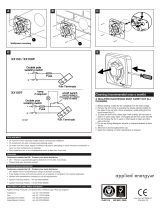
1 Remove the cover of the fan by
springing out the spring clips using a
3mm electrical screwdriver.
2 Remove the cable clamp.
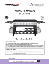
3 Wire the fan as shown in E , check
fan model to diagram.
4 Replace the cable clamp and two
screws. Ensure the cable is firmly
retained by the clamp.
5 Adjust the timer (if fitted): The timer
model XXS100T has a variable
overun timer of between 2 minutes
and 20 minutes. Turn the adjustment
screw X with an electrical
screwdriver clockwise to reduce the
time and anticlockwise to increase
the time. Test the timing is
satisfactory immediately after
connecting the electrical supply as
access will be limited after
completion of the installation.
6 Replace the terminal cover.
7 Switch off the mains electrical
supply and remove fuses.
8 Connect the cable from the isolating
switch to the electrical supply wiring.
Operate the fan using the double pole
isolating switch.
XXS100T only
Operate the fan using the on/off switch.
When the switch is turned off, the fan
continues to operate for the adjusted
time delay.
The grilles can be washed with a mild
household cleaner.
Using your fan
Cleaning
/