Page is loading ...

CARPET
FLOOR
1/2” MIN 1” MAX
2 5/8”
JOIST
COVER
BOX FRAME
#10 MINUMUM
SCR1032X1.5FPF
SCR832X1/2FPM
FP-1BB
CEMENT1/2” PLYWOOD
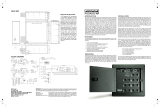
FP-1 and FP-2 Installation Instructions
whirlwind FP-1 and FP-2 Floor Pockets can be mounted directly into a cutout in a wooden
floor or can be installed on whirlwind FP-1BB and FP-2BB electrical style back boxes.
The FP-1BB and FP-2BB back boxes are N.E.M.A. Type 1 electrical enclosures 4” deep,
gray enamel with knockouts. 6” deep boxes, which provide more wiring space, are also
available as FP-1BB6 and FP-2BB6. whirlwind recommends using our back boxes to
ensure proper fit and hole alignment. Other brands of boxes may have incompatible
flange widths and mounting hole patterns. Verify compatibility before installation.
INSTALLATION WITHOUT BACK BOX
Use the supplied, full size template to lay out the hole pattern and cutout. The 5/32”
diameter holes allow for use of the supplied 10-32 x 1.5” type F screws to mount the box
frame. Other #10 flat head wood or tapping screws can also be used. The 3/16” diameter
holes in the FP-1 template are for clearance of the cover mounting screws.
INSTALLATION WITH BACK BOX
FP-1BB and FP-2 BB Back Boxes should be installed so that the top of the Back Box is
1/2 to 1” below the height of the finished floor. This allows for adjustment at final
installation and provides clearance for wiring in the bottom of the box. Conduits attached
to the box should be mounted as close as possible to the bottom of the box.
INSTALLATION IN CONCRETE
For installation in concrete attach a piece of 1/2 inch plywood of identical size to the top of
the back box and tape all open gaps. This will ensure that the back box is installed at a
correct depth so that the concrete is flush and will not leak in. Adjust depth for additional
flooring on top of the concrete. Before installation check building codes for additional
operations and or preparations.
REMOVABLE CONNECTOR PANELS
FP-1 and FP-2 floor pockets have removable end and bottom panels for connector
mounting. Two types of end plate are supplied; blank and pre punched for four whirlwind
WC3F and WC3M style connectors. The bottom panel can accept small multi pin
connectors and other types when used with a deep back box.
Whirlwind FP-1 & FP-2 floor pockets

Parts Explosions
NOTE : included SCREWS (SCR440X1/2FPM)
and NUTS (NUT4-40KEPS) for mounting WC3F
connectors to END PLATES not shown.
FP-1
FP-1BB (NOT INCLUDED)
4.125
6.125
6.125
SCR1032X1.5FPF (4)
FP-1 BOX FRAME
END PLATE BLANK
END PLATE
4 WC3F HOLES
BOTTOM PLATE
8
SCR832X1/2FPM (4)
8
SCR632X1/4PPF (4)
SCR632X1/4PPF (2)
COVER
FP-2
SCR832X1/2FPM (4)
COVER
BOTTOM PLATE
FP-2BB (NOT INCLUDED)
FP-2 BOX FRAME
END PLATE
4 WC3F HOLES (2)
6.125
14"
8"
SCR1032X1.5FPF (4)
SCR632X1/4PPF (6)
END PLATE
BLANK (2)
12
4.125
SCR632X1/4PPF (4)
99 Ling Road. Rochester, NY 14612
Phone 800 733-9473
Email: [email protected]
http://www.whirlwindusa.com
2.47
FP2 side and bottom plates
FP1 side and bottom plates
/
