
DATE CODE & P/N
WHIRLWIND ROCH, NY
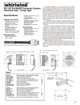
W4 176 Pin MASS Connector System
Technical Data - Crimp Type
Materials and Finishes:
Mechanical Data:
Contacts: Copper alloy, hard
gold plate over nickel under
plate per MIL-G-45204
Insulators: Low temperature
elastomer
"O" Rings and Seals: Low
temperature elastomer
Shells and Covers: All
aluminum alloy, black anodized
coating, chain-stainless steel
Operating Temperature:
-40 C to +105 C
-40 F to +221 F
Contacts: #20 AWG Crimp type
(7.5 Amp rating)
Contact Retention: 20 lbs.
minimum
Connector Engagement and
Separation Forces:
50 lbs. maximum
Polarization: Hermaphroditic
Electrical Data:
Operating Voltage: 500 VDC or
400 VAC rms max
Insulation Resistance: 2500
megohm minimum
Contact Resistance: 6
milliohms maximum
Specifications
The Whirlwind W4RP is a 176 contact version of the virtually
indestructible whirlwind Mass Connector. This new design uses crimp
type, replaceable pins and sockets. Like all Mass connectors, the
W4RP has equal numbers of both pins and sockets within the resilient
rubber insert. This arrangement allows two identical contact inserts to
mate, requiring only a panel mount or inline housing to complete the
assembly. Housings are made from machined aluminum and the
threaded locking ring ensures positive connection even under
adverse conditions. When mating two inline connectors, one locking
ring is merely unscrewed to expose threads, which are gripped by the
other locking ring.
To properly mate Mass connectors, unscrew the locking rings to
expose the inserts, align the inserts and push together using only
hand pressure and then screw the locking ring on to secure the
connection.
Due to the unique hermaphroditic design the usual connector
designations of male and female do not apply, therefore Mass
connectors are specified as Outputs and Inputs. An Output wired
connector must mate with an Input connector configuration. The
whirlwind wiring standard is odd numbered cable pairs attached to
pins and even numbered cable pairs attached to sockets in the Output
connector. Input wiring has odd pairs attached to sockets and even
pairs attached to pins. For example, channel one is on pins in the
Output connector and mates with channel one on sockets in the Input
connector, which maintains color coding throughout the system. For
planning system layout, whirlwind standard starts at the stage box and
designates the first connector as an Output.
Cables with Mass connectors at both ends require one end to be
wired as an Output and the other wired as Input. Each wire must
connect to a pin at one end and the same numbered socket at the
other. The W4RP will accommodate up to 58 balanced, shielded
signal lines.
®
(Strain relief Bushing adds approximately 2” to Inline)
3.0”
Strip wire 0.156”
1.75”
Insulator covers
transition between
foil and wires
3.77”
2.50”
W4CRP
M176-CHSQ
M176-CHCAP
M176R-INS
PT1-16BK-1.5
PT3-16BK-1.0
M1RPIN
M1RSKT
M1R-TOOL KIT
MANW3W4RP
W4IRP
M176R-INS
M176-IL
M176-ILCAP
M176-G
PT1-16BK-1.5
PT3-16BK-1.0
SCR8-32X1/2PH
Panel Connector / Cap, Wiring Kit Complete
Mass 176 Chassis Flange Black
Mass 176 Chassis Dust Cap
Mass 176 Pin and Socket Insert Black
Drain Wire Insulator 1/16” Blk Shrink Tube 1.5”
Mylar / Foil Insulator 3
Wiring Diagram for 176 Pin
Inline Connector / Cap, Wiring Kit Complete
Mass 176 Pin and Socket Insert Black
Mass 176 Inline Housing with Ring
Mass 176 Inline Dust Cap Blk
122-176 Inline Strain Relief Grip Range .75”-.875”
Chain Screw 8-32X1/2 Pan Head Phillips Blk
/16” Blk Shrink Tube 1.0”
Mass Gold Pins Male
Mass Gold Sockets Female
Tool Kit - Crimper, Locater, and Extractor
Drain Wire Insulator 1/16” Blk Shrink Tube 1.5”
Mylar / Foil Insulator 3/16” Blk Shrink Tube 1.0”
1
1
1
58
58
88
88
1
1
1
1
1
1
58
58
1
Parts
3.02”
Chain Length 8”
4.85” (with dust cap in place)
1.36”
1.77” (with dust cap in place)
3.0”
Chain Length 8”
3.25”
Panel cut out
2.875”
1.326”
Ø.25”
Cable preparation
Oversize and non-wire mesh strain relief available upon request
6/03

Output
Check for proper wire strip length by
pushing wire into a contact and looking to
see the wire strands through the hole in
the side. Load the contact into the crimp
tool locator and push the wire into place.
Squeeze the handles while making sure
that the wire stays in the wire hole . The
crimper is a full cycle racheting type and
can only be released by completing the
cycle, at which point the crimp contact will
pull freely from the tool. Inspect the
connection and continue, following the
color code to apply pins and sockets to
the proper wire pairs.
Load the pins and sockets into the
insert housing according to the pin out
color code. Contacts are inserted into the
hard plastic wafer and pushed into place
with the red handled end of the insertion
tool or small needle nose pliers. Fully
inserted contacts are locked in place by
spring metal retention clips embedded in
the plastic wafer. In the event a contact
must be removed from the insert use the
white handled, extraction end of the
contact tool. Carefully slip the tool into the
plastic wafer until the small hole in the end
of the extractor is even with the surface of
the wafer. Do not force the tool in as it is
easily deformed. Only when the tool is
properly seated will the spring fingers
release, allowing the contact to be
removed. If the wire is still attached, gently
pull the wire to remove it. If the wire is
broken, push the contact from the rubber
face side with an opposite contact until it
is exposed in the back.
PIN
W4 176
Pin MASS Connector System
Technical Data - Crimp Type
White EXTRACTION
Red INSERTION
Tip
Push from opposite side to remove
Make sure Contact
and Wire are fully inserted
before crimping
Crimp
AMP 91067-2
Inspection Hole
99 Ling Road . Rochester, NY 14612 . Phone 585 663-8820 . Fax 585 865-8930 . Email: [email protected] . http://www.whirlwindusa.com
Pin 3 Pin 2
(-) (+)
Black Red
Red White
Green White
White Blue
Blue Yellow
Brown Yellow
Brown Orange
Orange Yellow
Purple Orange
Gray White
Pink White
Beige White
Beige Brown
Beige Orange
Black White
Black Green
Black Blue
Black Yellow
Black Brown
Black Orange
Red Green
Red Blue
Red Yellow
Red Brown
Red Orange
Green Blue
Green Yellow
Green Brown
Green Orange
White Yellow
White Brown
White Orange
Blue Brown
Blue Orange
Purple Red
Purple White
Purple Green
Purple Blue
Purple Yellow
Purple Brown
Purple Black
Gray Brown
Gray Red
Gray Green
Gray Orange
Gray Yellow
Gray Black
Gray Blue
Pink Green
Pink Blue
Pink Yellow
Pink Brown
Pink Orange
Pink Purple
Pink Gray
Beige Green
Beige Blue
Beige Yellow
XLR
Pair #
1
2
3
4
5
6
7
8
9
10
11
12
13
14
15
16
17
18
19
20
21
22
23
24
25
26
27
28
29
30
31
32
33
34
35
36
37
38
39
40
41
42
43
44
45
46
47
48
49
50
51
52
53
54
55
56
57
58
58 Pair color code
Odd # = Pins
Even # = Sockets
Pin 1 = Shield
6/03
WIRING SIDE OF CONNECTOR
PINS
SOCKETS

W4 176
Pin MASS Connector System
Technical Data - Crimp Type
The W4RP is a rear insert, rear release crimp type connector. Contacts are
loaded into the insert body and removed from the rear (wiring side) of the
housing. To prepare the wires for use follow the diagram for removing the
jacket and the foil shield from the cable pair. Be careful not to nick and do not
tin the ends of the wire being stripped. Insulate the drain wires with the clear
PVC tubing and use the heat shrink tubing over the foil of each pair.
The whirlwind M1R-Tool Kit contains the required tools to attach the
contacts to the wires and to load or remove them from the insert housing. The
crimp tool body is a mil spec Daniels AFM8 with a whirlwind K13-3 contact
locator. The contact insertion/extraction tool is an AMP 91067-2.
Before attaching contacts to the wires, the selector knob on the top of the
crimp tool must be set for the proper gauge. Setting 5 is for 24 AWG such as
whirlwind multipair cable and setting 6 is for 22 AWG such as Belden 8451 and
1266A.
DATAPLATE
SELECTOR
KNOB
AFM8
Crimp Tool
K13-3
LOCATOR
WIRE SIZE
26
CONTACT
WHIRLWIND PIN
OR SOCKET CONTACT
24
22
20
4
5
6
7
99 Ling Road . Rochester, NY 14612 . Phone 585 663-8820 . Fax 585 865-8930 . Email: [email protected] . http://www.whirlwindusa.com
Input
Pin 3 Pin 2
(-) (+)
Black Red
Red White
Green White
White Blue
Blue Yellow
Brown Yellow
Brown Orange
Orange Yellow
Purple Orange
Gray White
Pink White
Beige White
Beige Brown
Beige Orange
Black White
Black Green
Black Blue
Black Yellow
Black Brown
Black Orange
Red Green
Red Blue
Red Yellow
Red Brown
Red Orange
Green Blue
Green Yellow
Green Brown
Green Orange
White Yellow
White Brown
White Orange
Blue Brown
Blue Orange
Purple Red
Purple White
Purple Green
Purple Blue
Purple Yellow
Purple Brown
Purple Black
Gray Brown
Gray Red
Gray Green
Gray Orange
Gray Yellow
Gray Black
Gray Blue
Pink Green
Pink Blue
Pink Yellow
Pink Brown
Pink Orange
Pink Purple
Pink Gray
Beige Green
Beige Blue
Beige Yellow
XLR
Pair #
1
2
3
4
5
6
7
8
9
10
11
12
13
14
15
16
17
18
19
20
21
22
23
24
25
26
27
28
29
30
31
32
33
34
35
36
37
38
39
40
41
42
43
44
45
46
47
48
49
50
51
52
53
54
55
56
57
58
58 Pair color code
Odd # = Sockets
Even # = Pins
Pin 1 = Shield
6/03
WIRING SIDE OF CONNECTOR
PINS
SOCKETS
-
 1
1
-
 2
2
-
 3
3
Ask a question and I''ll find the answer in the document
Finding information in a document is now easier with AI
Related papers
-
 Whirlwind W3 MASS User manual
-
 Whirlwind WMKPVC User manual
-
 Whirlwind MultiDirector Owner's manual
-
 Whirlwind PYROBOX User manual
-
 Whirlwind Selector AB Pedal Owner's manual
-
 Whirlwind W6 MicroMASS User manual
-
 Whirlwind W5 48 User manual
-
 Whirlwind Wall Frame Door User manual
-
 Whirlwind THS 1 User manual
-
 Whirlwind pcUSB User manual
Other documents
-
CableWholesale 10U3-02115E Datasheet
-
Southwire 64168845 Specification
-
 MQ Multiquip GAW180HE Operating instructions
-
Ideal 33-700 User manual
-
 MegaTech Whirlwind 3000 User manual
-
 MAC Panel 7853106-02 Assembly Manual
-
Crestron DM-8G-CONN User guide
-
Toro Giant Bag Kit, 19" and 21" Whirlwind Installation guide
-
 Painless Performance LS1 User manual
-
 Painless Performance 2000 - 2002 GM VORTEC THROTTLE BY WIRE 60219 User manual


