Page is loading ...

T
DiCoder
®
CKS36:
Programmable
Motor Feedback System for
Installation in Electric Motors
D A T A S H E E T
The CKS36 Encoder belongs to
a new generation of optical
encoders.
What they all have in common is
the new mini-disc (MiDi) tech-
nology.
This generation has a special
feature: a very small code disc
with a code track radius of only
2 mm permitting holistic (integral)
scanning and at the same time
providing high shock and vibration
resistance.
In doing so, the system compensa-
tes for the eccentricity errors of the
code disc, ball bearing and shaft,
which are unavoidable in conventio-
nal systems.
By arranging the code disc in the
centre of the rotational axis, high an-
gular velocities are no longer limited
by the code disc. The encoder size
is essentially determined by the
mechanical and electrical interfaces.
Technologies such as “Chip On
Board” are used to achieve this.
The number of components is
reduced to a minimum.
Incremental signals with resolutions
of up to 2,048 lines per revolution
and commutation signals of up
to 32 pole pairs are available.
A freely user-programmable version
is also available.
Number of lines
up to 2,048,
1-32 pole pairs
Motor Feedback Systems

2
SICK-STEGMANN
Motor Feedback System CKS36
Resolution up to 2,048
Pulses per revolution
Number of pole pairs: from 1 to 32
Zero pulse 90° or 180°
Working temperature range
– 20°C to + 110 °C
Programmable
PIN and core allocation
Accessories
Connection technology
Fixing technology
Programming and Adjustment Tool
40 -2
Ø 45
1:3
Ø 8
5
3
7. 2
Ø 38
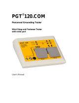
Ma 4 Nm
8
1.5
Ø 6.5
M4
Lense screw M3x8 (2x) DIN 7985
with Torx head
Thread tapped to DIn 7500
Dimensional drawing CKS36
General tolerances to DIN ISO 2768-mk
A
PIN Signal Colour of cores
Explanation
1 Z violet
Reference signal
2 Z yellow
Reference signal inverted
3 A white
k
Incremental signal
4 A brown
Incremental signal inverted
5 B pink
Incremental signal
6 B black
Incremental signal inverted
7 R white/green
Commutation signal
8 R white/pink
Commutation signal inverted
9 S white/yellow
Commutation signal
10 S white/blue
Commutation signal inverted
11 T white/grey
Commutation signal
12 T white/red
Commutation signal inverted
13 U
s
red
Supply voltage 5 V ± 10%
14 GND blue
Ground connection
15 U
s
–
Sense +
1)
16 GND –
Sense –
1)
17 N. C. –
Not connected
1)
18 SET –
Signal input for zero adjustment
All
output signals are adjusted to the position of the zero
pulse. A level of
> 2.5 V
U
s
must be maintained for at
least
220 µs
in order to execute this function.
1)
1
19 SDA –
Data signal of the parameterisation interface
1)
20 SCL –
Clock pulse signal of the parameterisation interface
1)
1)
(not in stranded cable)
Electrical zero adjustment
Caution: Pins labelled N. C. must
not be occupied!
1
Number of lines
up to 2,048,
1-32 pole pairs
Motor Feedback Systems
Proposed customer fitting
Ø 6.5
Ø min. 8
Ø max. 12
60°
9.462°
–3
l
Ø max. 32
Ø
5.5
3.4
2
0.02
A
1:3
R
z
6.3
13
10
0.4
7. 4
+0.2
A
M4

3
CKS36
SICK-STEGMANN
Lines per revolution 1 … 2,048
Commutation signales 1 … 32 pole pairs
Dimensions mm (see dimensional drawing)
Mass 0.065 kg
Moment of inertia of the rotor 4.5 gcm
2
Measurement step 90°/number of lines
Reference signal Number 1
Position configurable 90° or 180°
electr., logically linked with A and B
Error limits
„binary“ number of lines
1)
± 0.09 degrees
„non-binary“ number of lines
2)
± 0.13 degrees
Measurement step deviation
„binary“ number of lines
1)
± 0.035 degrees
„non-binary“ number of lines
2)
± 0.07 degrees
Operating speed
3) + 3.1)
12,000 min
-1
Max. output fequency TTL/RS 422 400 KHz
Max. angular acceleration 5 x 10
5
rad/s
2
Operating torque 0.2 Ncm
Starting torque 0.3 Ncm
Permissible shaft movement
static radial/axial ± 0.1 mm/± 0.2 mm
dynamic radial/axial ± 0.05 mm/± 0.1 mm
Bearing lifetime 3.6 x 10
9
revolutions
Working temperature range –20 … + 110 °C
Storage temperature range
4)
– 40 … + 125 °C
Permissible relative humidity
5)
90 %
Resistance
to shocks
6)
100 g (6 ms)
to vibration
7)
50 g (10 … 2000 Hz)
Protection class acc. IEC 60529
8)
IP 50
EMC
9)
Operating voltage range 5 V ± 10 %
Max. operating current, no load 60 mA
Interface signals:
Incremental and commutation signals to EIA 422
Parameterisation interface IIC Bus
CKS
Technical data to DIN 32878 CKS36
1)
„Binary“ number of lines
2
n
, n is a whole number
2)
„Non binary“ number of lines
2
n
, n is not a whole number
3)
In the case of a higher speed, the output signals
may be incorrect.
3.1)
Self warming 1,1K/1000 min
-1
when applying, note working temperature range.
4)
Without packaging
5)
Condensation not permissible
6)
To DIN EN 60068-2-27
7)
To DIN EN 60068-2-6
8)
With mating connector inserted and closed cover
9)
To DIN EN 61000-6-2 and DIN 61000-6-3
The EMC according to the standards quoted is achieved
when the motor feedback system is mounted in an electrically
conductive housing, which is connected to the central earthing
point of the motor controller via a cable screen. This is also
where the GND (0 V) connection of the supply voltage is linked
to earth.
Users must perform their own tests when other screen designs
are used.

4
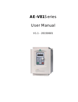
Incremental signals/Pulse-Time Diagram
SICK-STEGMANN
Incremental signals
At constant speed,
looking at the input
shaft, and clockwise
rotation.
By linking the two signals A and B, an output sig-
nal is created whose cycle durations tx1 … tx4
have different sizes.
The differences are determined:
1. by the mark/space ratio tolerance of the in-
dividual channels
2. by the tolerance in the 90° phase shift
between A and B
3. by the frequency
Ideally, the times tx1 … tx4 should always be
1/4 of the cycle duration T.
T
tx1
tx2
tx3
tx4
90 %
10 %
A
A
B
B
Z
Z
A + B
Time t
Pulse-time diagram
Z
R
S
T
e
f g h i k
a
Pole pairs Number of poles e, f, g, h, i, k
Example: 2 4 30° 180°
n n
·
2 360°/6n 360°/n
n = 1 … 32
The angular data is related to a mechanical
shaft rotation.
Precision of the signals R, S, T ± 1°.
Programmable version of the CKS36 (type: CKS36-PFBPROGR; part no. 1035370)
This product option of the CKS36 can be freely
programmed by the user. With the programming
and adjustment tool (PGT-06-S), the following
values can be individually programmed.
Zero puls width
Number of pole pairs
Number of lines
Adjustable values
90° or 180°
1 to 32
1 to 2,048
Default settings
90°
32
2,048
Caution!
In the case of CKS36 ordered with fixed
defined values (e. g. 90° zero pulse width,
1,024 lines, 4 pole pairs), these parameters
can not be modified.

5
SICK-STEGMANN
CKS36
C
Position 1
K
Position 2
S
Position 3
3
Position 4
6
Position 5
–
Position 6 Position 7
F
Position 8
B
Position 9 Position 10 Position 11 Position 12 Position 13 Position 14
Motor Feedback System CKS36 – fixed defined values (these values cannot be modified by the user)
C
Position 1
K
Position 2
S
Position 3
3
Position 4
6
Position 5
–
Position 6
A
Position 7
F
Position 8
B
Position 9
8
Position 10
0
Position 11
0
Position 12
0
Position 13
4
Position 14
Electrical interfaces
5 V, RS 422,
90° zero pulse width = A
5 V, RS 422,
180° zero pulse width = B
C
Position 1
K
Position 2
S
Position 3
3
Position 4
6
Position 5
–
Position 6 Position 7
F
Position 8
B
Position 9 Position 10 Position 11 Position 12 Position 13 Position 14
Ordering information CKS36
Please enter your individual encoder here
Ordering example: Motor Feedback System CKS36
90° zero pulse width, 2,048 number of lines, 4 pole pairs
2 pole pairs = 02
Pole pairs
1 pole pair = 01128 = 080
Lines per revolution
256 = 100
512 = 200
1024 = 400
2048 = 800
500 = 1F4
1000 = 3E8
2000 = 7D0
3 pole pairs = 03
4 pole pairs = 04
6 pole pairs = 06
8 pole pairs = 08
10 pole pairs = 10
12 pole pairs = 12
16 pole pairs = 16
Delivery settings:
90° zero pulse width, 2,048 lines, 32 pole pairs
1035370
Part no.
CKS36-PFBPROGR
Type
Motor Feedback System CKS36 – programmable
Description
Motor Feedback System CKS36 – freely programmable

6
Accessories – Connection Technology/Fixing Technology/Programming Tool
SICK-STEGMANN
2031079
Part no.
BEF-MW-SKX36
Type
Assembly tool SKX36
Description
Type
6030948DOL-1J14-GOM2XB7
Part no.
14
Contacts
0.2 m
Wire length
Stranded cable, straight, 14 cores, 14 x 0,15 mm
2
7
220
+5
70
+5
20
+5
Shrunk area
X
Ø
4.3
–0.5
20
2
191
View X
1035236PGT-06-S
Part no.Type
Assembly tool
Programming- and Adjustment Tool
Description
Programming and Adjustment Tool
• 110-230 V power supply unit
• USB cable
• Sub-D to encoder connector
• CD with programming tool software
SW10
–0.2

7
SICK-STEGMANN
CKS36

8 011 318/2009-03-10 • MD/4/200 • Printed in Germany (07.05) • Subject to change without notice . The specified product features and technical data do not represent any guarantee . 01 A4 Ste 2c int28
SICK AG • Waldkirch • Germany • www.sick.com
SICK STEGMANN GmbH • Donaueschingen • Germany • www.sick-stegmann.de
Australia
Phone +61 3 9497 4100
1800 33 48 02 – tollfree
E-Mail [email protected]
Belgium/Luxembourg
Phone +32 (0)2 466 55 66
E-Mail [email protected]
Brasil
Phone +55 11 5091-4900
E-Mail [email protected]
Ceská Republika
Phone +420 2 57 91 18 50
E-Mail [email protected]
China
Phone +852-2763 6966
E-Mail [email protected]
Danmark
Phone +45 45 82 64 00
E-Mail [email protected]
Deutschland
Phone +49 211 5301-250
E-Mail [email protected]
España
Phone +34 93 480 31 00
E-Mail [email protected]
France
Phone +33 1 64 62 35 00
E-Mail [email protected]
Great Britain
Phone +44 (0)1727 831121
E-Mail [email protected]
India
Phone +91–22–2822 7084
E-Mail [email protected]
Italia
Phone +39 011 79 79 65
E-Mail [email protected]
Japan
Phone +81 (0)3 3358 1341
E-Mail sup[email protected]
Nederlands
Phone +31 (0)30 229 25 44
E-Mail [email protected]
Norge
Phone +47 67 81 50 00
E-Mail austefjor[email protected]
Österreich
Phone +43 (0)22 36 62 28 8-0
E-Mail of[email protected]
Polska
Phone +48 22 837 40 50
E-Mail [email protected]
Republic of Korea
Phone +82-2 786 6321/4
E-Mail [email protected]
Republika Slowenija
Phone +386 (0)1-47 69 990
E-Mail of[email protected]
Russia
Phone +7 495 775 05 34
E-Mail denis.kesaev@
sickautomation.ru
Schweiz
Phone +41 41 619 29 39
E-Mail contact@sick.ch
Singapore
Phone +65 6744 3732
E-Mail [email protected]
Suomi
Phone +358-9-25 15 800
E-Mail [email protected]
Sverige
Phone +46 10 110 10 00
E-Mail [email protected]
Taiwan
Phone +886 2 2365-6292
E-Mail sickgr[email protected]
Türkiye
Phone +90 216 587 74 00
E-Mail [email protected]
USA
Phone +1 937-454-1956
E-Mail sales@stegmann.com
More representatives and agencies
in all major industrial nations at
www.sick.com
/