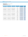
SICK DLS40 Incremental Encoders Product information
- Type
- Product information
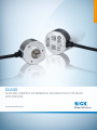
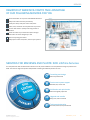
SICK DLS40 Incremental Encoders are slim and compact encoders that are suitable for a wide range of applications, including printing and packaging, paper processing, and metal, wood, and glass processing. They are also well-suited for use in AGVs, manufacturing and filling of bottles, asynchronous motors, and cable manufacturing.
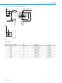
The DLS40 encoders have a variety of features that make them ideal for these applications. These features include:
-
A compact design that facilitates the integration of the encoder even where installation space is limited.
-
A flange with integrated housing that enables a very compact and cost-efficient design.
SICK DLS40 Incremental Encoders are slim and compact encoders that are suitable for a wide range of applications, including printing and packaging, paper processing, and metal, wood, and glass processing. They are also well-suited for use in AGVs, manufacturing and filling of bottles, asynchronous motors, and cable manufacturing.
The DLS40 encoders have a variety of features that make them ideal for these applications. These features include:
-
A compact design that facilitates the integration of the encoder even where installation space is limited.
-
A flange with integrated housing that enables a very compact and cost-efficient design.


-
 1
1
-
 2
2
-
 3
3
-
 4
4
-
 5
5
-
 6
6
-
 7
7
-
 8
8
-
 9
9
-
 10
10
-
 11
11
-
 12
12
-
 13
13
-
 14
14
-
 15
15
-
 16
16


SICK DLS40 Incremental Encoders Product information
- Type
- Product information
SICK DLS40 Incremental Encoders are slim and compact encoders that are suitable for a wide range of applications, including printing and packaging, paper processing, and metal, wood, and glass processing. They are also well-suited for use in AGVs, manufacturing and filling of bottles, asynchronous motors, and cable manufacturing.
The DLS40 encoders have a variety of features that make them ideal for these applications. These features include:
-
A compact design that facilitates the integration of the encoder even where installation space is limited.
-
A flange with integrated housing that enables a very compact and cost-efficient design.
Ask a question and I''ll find the answer in the document
Finding information in a document is now easier with AI
Related papers
-
SICK DFS60 INOX Product information
-
-
-
-
-
-
-
-
-
Other documents
-
 MCED systems BEF-02 User manual
-
Baumer PMG10P - Incremental Installation and Operating Instructions
-
 Dixon RP BA Actuator User manual
-
ABB FEN-31 User manual
-
MARK-10 Series STH Torque Sensor User guide
-
-
-

