Page is loading ...

HOTWIRE
5170 REMOTE
TERMINATION UNIT
USER’S GUIDE
Document No. 5100-A2-GB22-10
April 1997

Printed on recycled paper
A
5100-A2-GB22-10
April 1997
Copyright 1997 Paradyne Corporation.
All rights reserved.
Printed in U.S.A.
Notice
This publication is protected by federal copyright law. No part of this publication may be copied or distributed,
transmitted, transcribed, stored in a retrieval system, or translated into any human or computer language in any form
or by any means, electronic, mechanical, magnetic, manual or otherwise, or disclosed to third parties without the
express written permission of Paradyne Corporation, 8545 126th Avenue North, P.O. Box 2826, Largo,
Florida 33779-2826.
Paradyne Corporation makes no representation or warranties with respect to the contents hereof and specifically
disclaims any implied warranties of merchantability or fitness for a particular purpose. Further, Paradyne Corporation
reserves the right to revise this publication and to make changes from time to time in the contents hereof without
obligation of Paradyne Corporation to notify any person of such revision or changes.
Changes and enhancements to the product and to the information herein will be documented and issued as a new
release to this manual.
Warranty, Sales, and Service Information
Contact your sales or service representative directly for any help needed. For additional information concerning
warranty, sales, service, repair, installation, documentation, or training, use one of the following methods:
Via the Internet: Visit the Paradyne World Wide Web site at http://www.paradyne.com
Via Telephone: Call our automated call system to receive current information via fax or to speak with a
company representative.
— Within the U.S.A., call 1-800-870-2221
— International, call 727-530-2340
Trademarks
All products and services mentioned herein are the trademarks, service marks, registered trademarks or registered
service marks of their respective owners.

Important Regulatory Information
B
5100-A2-GB22-10 April 1997
Important Safety Instructions
1. Read and follow all warning notices and instructions marked on the product or included in the manual.
2. When an ac power source is used, this product is intended to be used with a 3-wire grounding type plug – a plug
which has a grounding pin. This is a safety feature. Equipment grounding is vital to ensure safe operation. Do not
defeat the purpose of the grounding type plug by modifying the plug or using an adapter.
Prior to installation, use an outlet tester or a voltmeter to check the ac receptacle for the presence of earth
ground. If the receptacle is not properly grounded, the installation must not continue until a qualified electrician
has corrected the problem.
If a 3-wire grounding type power source is not available, consult a qualified electrician to determine another
method of grounding the equipment.
3. Slots and openings in the cabinet are provided for ventilation. To ensure reliable operation of the product and to
protect it from overheating, these slots and openings must not be blocked or covered.
4. Do not allow anything to rest on the power cord and do not locate the product where persons will walk on the
power cord.
5. Do not attempt to service this product yourself, as opening or removing covers may expose you to dangerous
high voltage points or other risks. Refer all servicing to qualified service personnel.
6. General purpose cables are provided with this product. Special cables, which may be required by the regulatory
inspection authority for the installation site, are the responsibility of the customer. Use a UL Listed, CSA certified,
minimum No. 26 AWG line cord for connection to the telephone network.
7. When installed in the final configuration, the product must comply with the applicable Safety Standards and
regulatory requirements of the country in which it is installed. If necessary, consult with the appropriate regulatory
agencies and inspection authorities to ensure compliance.
8. A rare phenomenon can create a voltage potential between the earth grounds of two or more buildings. If
products installed in separate buildings are interconnected, the voltage potential may cause a hazardous
condition. Consult a qualified electrical consultant to determine whether or not this phenomenon exists and, if
necessary, implement corrective action prior to interconnecting the products.
9. Input power to the ac voltage configuration of this product must be provided by one of the following: (1) a UL
Listed/CSA certified power source with a Class 2 or Limited Power Source (LPS) output for use in North America,
or (2) a certified power source with a Safety Extra Low Voltage (SELV) output for use in the country of installation.
10. In addition, if the equipment is to be used with telecommunications circuits, take the following precautions:
— Never install telephone wiring during a lightning storm.
— Never install telephone jacks in wet locations unless the jack is specifically designed for wet locations.
— Never touch uninsulated telephone wires or terminals unless the telephone line has been disconnected at the
network interface.
— Use caution when installing or modifying telephone lines.
— Avoid using a telephone (other than a cordless type) during an electrical storm. There may be a remote risk of
electric shock from lightning.
— Do not use the telephone to report a gas leak in the vicinity of the leak.
!
WARNING:
To Users of Digital Apparatus in Canada:
This Class B digital apparatus meets all requirements of the Canadian interference-causing equipment
regulations.
Cet appareil numérique de la classe B respecte toutes les exigences du règlement sur le matérial
brouilleur du Canada.

Important Regulatory Information
C
5100-A2-GB22-10
April 1997
Declaration of Conformity
This Declaration of Conformity is made by Paradyne Corporation pursuant to Parts 2 and 15 of the Federal
Communications Commission’s Rules. This compliance information statement pertains to the following products:
Trade Name: HOTWIRE
Model Number: 5170-A1-201
This device complies with Part 15 of the FCC Rules. Operation is subject to the following two conditions: (1) this
device may not cause harmful interference, and (2) this device must accept any interference received, including
interference that may cause undesired operation.
The name, address, and telephone number of the responsible party is given below:
Paradyne Corporation
8545 126th Ave. No.
Largo, Florida 33773
Phone: (813) 530-2000
The authority to operate this equipment is conditioned by the requirement that no modifications will be made to the
equipment unless the changes or modifications are expressly approved by Paradyne Corporation.
This product was tested with a shielded cable attached to the serial port. A shielded cable must be used with the
product to ensure FCC compliance.

i
5100-A2-GB22-10
April 1997
Contents
About This Guide
Purpose and Audience iii. . . . . . . . . . . . . . . . . . . . . . . . . . . . . . . . . . . . . . . . . . .
Guide Summary iii. . . . . . . . . . . . . . . . . . . . . . . . . . . . . . . . . . . . . . . . . . . . . . . .
Product-Related Documents iv. . . . . . . . . . . . . . . . . . . . . . . . . . . . . . . . . . . . . .
1 About HotWire 5100 DSL Access System
What is the HotWire 5100 DSL Access System? 1-1. . . . . . . . . . . . . . . . . . . .
About the 5170 Remote Termination Unit 1-2. . . . . . . . . . . . . . . . . . . . . . . . . . .
Features 1-2. . . . . . . . . . . . . . . . . . . . . . . . . . . . . . . . . . . . . . . . . . . . . . . . . . . . . . .
Equipment and Software Requirements 1-3. . . . . . . . . . . . . . . . . . . . . . . . . . . .
HotWire 5170 RTU Diagnostics Utility 1-3. . . . . . . . . . . . . . . . . . . . . . . . . . . . .
User Interface 1-3. . . . . . . . . . . . . . . . . . . . . . . . . . . . . . . . . . . . . . . . . . . . . . .
2 Installation
Before You Begin 2-1. . . . . . . . . . . . . . . . . . . . . . . . . . . . . . . . . . . . . . . . . . . . . . .
Package Contents 2-1. . . . . . . . . . . . . . . . . . . . . . . . . . . . . . . . . . . . . . . . . . . . . .
Installing the HotWire 5170 Remote Termination Unit 2-2. . . . . . . . . . . . . . . .
About the RTU Rear Panel 2-2. . . . . . . . . . . . . . . . . . . . . . . . . . . . . . . . . . .
Power-Up Self-Test 2-5. . . . . . . . . . . . . . . . . . . . . . . . . . . . . . . . . . . . . . . . . . . . . .
Installing the HotWire 5170 RTU Diagnostics Utility 2-6. . . . . . . . . . . . . . . . . .

Contents
ii
5100-A2-GB22-10
April 1997
3 Using the HotWire Diagnostics Utility
Troubleshooting 3-1. . . . . . . . . . . . . . . . . . . . . . . . . . . . . . . . . . . . . . . . . . . . . . . . .
Accessing the Main Menu 3-3. . . . . . . . . . . . . . . . . . . . . . . . . . . . . . . . . . . . . . . .
Setting the Communication Port 3-4. . . . . . . . . . . . . . . . . . . . . . . . . . . . . . . . . . .
Setting/Changing MAC Address 3-5. . . . . . . . . . . . . . . . . . . . . . . . . . . . . . . . . . .
Checking RTU Status 3-6. . . . . . . . . . . . . . . . . . . . . . . . . . . . . . . . . . . . . . . . . . . .
Resetting the RTU 3-7. . . . . . . . . . . . . . . . . . . . . . . . . . . . . . . . . . . . . . . . . . . . . .
Viewing Utility and Firmware Version Numbers 3-7. . . . . . . . . . . . . . . . . . . . . .
Viewing Transmission Statistics and Network Status 3-8. . . . . . . . . . . . . . . . .
Running Loopback Tests 3-9. . . . . . . . . . . . . . . . . . . . . . . . . . . . . . . . . . . . . . . . .
Loopback Test Results 3-10. . . . . . . . . . . . . . . . . . . . . . . . . . . . . . . . . . . . . . .
Downloading Firmware 3-11. . . . . . . . . . . . . . . . . . . . . . . . . . . . . . . . . . . . . . . . . .
Exiting the Utility 3-11. . . . . . . . . . . . . . . . . . . . . . . . . . . . . . . . . . . . . . . . . . . . . . . .
A LEDs
B Pin Assignments
DSL Interface B-1. . . . . . . . . . . . . . . . . . . . . . . . . . . . . . . . . . . . . . . . . . . . . . . . . . .
LAN (Ethernet) Interface B-2. . . . . . . . . . . . . . . . . . . . . . . . . . . . . . . . . . . . . . . . .
Ethernet Loopback Cable B-2. . . . . . . . . . . . . . . . . . . . . . . . . . . . . . . . . . . . .
RS-232 Interface B-3. . . . . . . . . . . . . . . . . . . . . . . . . . . . . . . . . . . . . . . . . . . . . . . .
C Technical Specifications
Glossary
Index

iii
5100-A2-GB22-10
April 1997
About This Guide
Purpose and Audience
This guide describes how to install and run diagnostics on the 5170 Remote
Termination Unit (RTU). The guide is written for users of the HotWire 5100 Digital
Subscriber Line (DSL) Access System.
Guide Summary
Section Description
Chapter 1
About HotWire 5100 DSL Access System.
Provides a
high-level overview of the operation of the HotWire 5100 DSL
Access System, an overview of the HotWire 5170 RTU, and
the hardware and software requirements.
Chapter 2
Installation.
Describes how to install the RTU and Diagnostic
Utility.
Chapter 3
Using the HotWire Diagnostics Utility.
Describes how to use
the HotWire Diagnostics Utility.
Appendix A
LEDs.
Provides the LED descriptions.
Appendix B
Pin Assignments.
Provides the pinouts used for the interface
connectors at the rear of the RTU.
Appendix C
Technical Specifications.
Provides the specifications for the
RTU.
Glossary Defines acronyms and terms used in this document.
Index Lists key terms, acronyms, concepts, and sections in
alphabetical order and provides page references.

About This Guide
iv
5100-A2-GB22-10
April 1997
Product-Related Documents
Document Number Document Title
5100-A2-GB20
HotWire 5100 DSL Access System Central Office
Access Concentrator User’s Guide

1-1
5100-A2-GB22-10
April 1997
About HotWire 5100 DSL Access
System
1
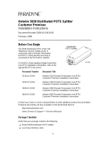
What is the HotWire 5100 DSL Access System?
Your HotWire 5170 Remote Termination Unit (RTU) is a component in the
HotWire 5100 DSL Access System. This system provides high-speed Internet or
corporate LAN access over traditional twisted-pair telephone wiring. Using your
RTU, you can connect to a Central Office (CO) to access Internet service
providers or corporate networks.
PC with
HotWire
5170
Diagnostic
Utility
PC with
HotWire
5170
Diagnostic
Utility
Splitter*
Phone
Splitter*
Phone
Router
Domain
Name Server
497-15203-01
*A splitter is an interface device installed by a CO technician
outside your premises.
Central
Office
5170
To Internet
Service
Providers
5170

About HotWire 5100 DSL Access System
1-2
5100-A2-GB22-10
April 1997
About the 5170 Remote Termination Unit
The HotWire 5170 RTU is a standalone unit designed for the home office users
with a local area network (LAN). It provides high-speed internet access via the
DSL interface to a central office. The built-in Rate Adaptive DSL (RADSL)
technology enables the unit to automatically communicate with the CO at the
maximum possible operating rate. The RTU communicates with your
IBM-compatible 80486 (or higher) PC using your Ethernet network interface card
(NIC). The supplied windows-based diagnostics utility enables users to check
RTU status, network transmission status, and run diagnostic tests.
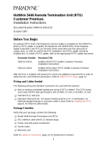
As shown in the following illustration, the RTU front panel provides several LEDs
to indicate RTU operating status. Refer to Appendix A,
LEDs
, for the descriptions
of the LEDs and their operational status indications.
496-15216
RX
CD
LNK
DSL LINK
LAN
5170
TX
RX
COL
SYS
TEST
JAB
TX
PWR
Features
Your 5170 RTU has the following features:
Supports CAP Rate Adaptive Digital Subscriber Loop (CAP RADSL)
High-speed access rates which vary depending on the RADSL
Security features in the HotWire CO hardware that prevent remote users from
accessing another remote user’s PC files or LAN traffic
Prevents degradation of telephone service while in use

About HotWire 5100 DSL Access System
1-3
5100-A2-GB22-10
April 1997
Equipment and Software Requirements
Verify that you have the following hardware and software before installing the
RTU.
Hardware Requirements
80486 (or higher) IBM PC or compatible
8 MB RAM minimum (16 MB RAM recommended)
One 1.44 MB, 3 1/2″ diskette drive (for installation)
2 MB free disk storage (for program files)
Software Requirements
DOS 5.0 or later
Windows for Workgroups 3.11 (or later) or Windows 95
HotWire 5170 RTU Diagnostics Utility
Use the HotWire 5170 Diagnostics Utility supplied with the RTU for running
diagnostics and tests for troubleshooting the unit or downloading firmware. The
Diagnostics Utility provides screen help in standard Windows format. Refer to
Chapter 3,
Using the HotWire Diagnostics Utility,
for more information on this
utility.
User Interface
The Diagnostics Utility uses standard Windows user interface conventions for all
windows including Help screens.

2-1
5100-A2-GB22-10
April 1997
Installation
2
Before You Begin
1. Check your package contents.
2. Review software and hardware requirements in Chapter 1.
3. Begin installation.
Package Contents
Your HotWire 5100 RTU package should contain the following:
HotWire 5170 Remote Termination Unit
HotWire 5170 Diagnostics Utility disk
6-pin modular cable (DSL connection)
HotWire 5170 Remote Termination Unit User’s Guide

Installation
2-2
5100-A2-GB22-10
April 1997
Installing the HotWire 5170 Remote
Termination Unit
For RTU installation, you need the following:
Cables and cord supplied in your HotWire 5170 RTU package.
A DSL access point already installed and near the location of the RTU.
An Ethernet card already installed in your PC.
An available 110V ac power source.
You may also want a small screwdriver to secure your serial port connectors. If
you ever need to perform the External Ethernet loopback test on your Ethernet
card, you will also need an Ethernet Loop cable. This is not supplied with your
RTU but the pin assignments and wiring to make this cable, along with the pin
assignments for all the other cables, are provided in Appendix B,
Pin
Assignments
.
About the RTU Rear Panel
The following figure shows the rear panel for your RTU. The installation uses the
following jacks and port:
DSL
Serial (optional)
LAN
PWR
The V.35 port is not used but is included to accommodate future enhancements
to this product.
01
PWR
LAN
SERIAL PORT/V.35
DSL
496-15215
Use the following procedure to install your RTU.

Installation
2-3
5100-A2-GB22-10
April 1997
Procedure
1. Turn Off your PC. Place your RTU on a flat surface near the PC.
2. Insert the DSL cable 6-pin plug into the jack marked DSL on your RTU. Insert
the other end of the cable into the DSL network access point.
.
01
PWR
LAN
SERIAL PORT/V.35
DSL
DSL
Cable
496-15207
3. This step is optional. Make this RS-232 connection only to accommodate
running the 5170 Diagnostic Utility. See Chapter 3,
Using the HotWire
Diagnostics Utility,
for a description of this utility.
Insert the 25-pin connector on the shielded RS-232 cable into the connector
marked SERIAL PORT on your RTU. Insert the other end of the cable into
the serial port on your PC.
01
PWR
LAN
SERIAL PORT/V.35
DSL
496-15208
Shielded
RS-232
Cable

Installation
2-4
5100-A2-GB22-10
April 1997
4. Insert the Ethernet cable 8-pin plug into the jack marked LAN on your RTU.
Insert the other end of the cable into the Ethernet jack on the Ethernet card in
your PC.
01
PWR
LAN
SERIAL PORT/V.35
DSL
496-15209
Ethernet
Cable
5. Connect the small power connector into the jack marked PWR on your RTU.
Plug the transformer end of the power cord into a 110V ac power outlet.
01
PWR
LAN
SERIAL PORT/V.35
DSL
496-15210
Power
Cable
Power
On/Off

Installation
2-5
5100-A2-GB22-10
April 1997
6. Turn on your PC.
7. Turn on the power switch on your RTU (see rear panel illustration). Verify that
the LEDs function as indicated in the following illustration:
496-15217
The SYS LED turns
solid green. Refer to
the
Power-Up Self-Test
section following this
procedure if the
SYS LED does not
turn green.
The CD LED blinks and then both
the CD and LNK LEDs turn solid
green. This indicates that the card
is communicating with the central
office unit, meaning your DSL link
is operational. If the CD and LNK
LEDs do not function as stated,
contact your customer service
representative for assistance.
RX
CD
LNK
DSL LINK
LAN
5170
TX
RX
COL
SYS
TEST
JAB
TX
PWR
Installation is completed. You can begin using your DSL connection. Refer to
Troubleshooting
in Chapter 3 if you encounter problems during normal RTU
operation.
Power-Up Self-Test
Whenever you turn on your RTU or after the reset operation is selected in the
Diagnostics Utility, a power-up self-test is automatically performed on the RTU to
ensure that the unit is installed and functioning properly. The self-test includes a
basic hardware test and verification of internal components. The SYS (system)
LED state identifies the following conditions by:
Turning solid green if the test is successful.
Turning Off if the test fails.
If the test fails, turn power Off and On. You may also use the diagnostics utility to
reset the device; see
Resetting the RTU
in Chapter 3. If the test continues to fail,
contact your customer service representative for assistance.

Installation
2-6
5100-A2-GB22-10
April 1997
Installing the HotWire 5170 RTU Diagnostics Utility
The RS232 cable must be connected between the RTU and your PC before you
can run the Diagnostic Utility.
Procedure
To install the Diagnostics Utility:
1. Insert the HotWire 5170 RTU Diagnostics Utility disk into drive a:.
2. Enter Windows and:
If you are . . .
Select . . .
Using Windows for Workgroups 3.11 File, then Run on the Program Manager
window.
Using Windows 95 Start, then Run.
3. Type A:\SETUP.EXE and click on OK.
4. Follow the screen instructions for installing the software. When the install
program prompts for a destination directory for the Diagnostics Utility, you
can specify a directory or click on Next to accept the default directory.
5. Click on OK when installation completes.
An icon is created for the utility. You can double-click on the icon to start the utility
when needed.
NOTE:
The Diagnostics Utility interferes with network data and operation of the RTU
so the Diagnostics Utility should not be running, either in the open state or
iconified, during normal RTU operation.
When you first access the utility, you must configure the COM port used for the
RS-232 connection. The following window prompts you to do this. Refer to
Setting the Communication Port
in Chapter 3 for more information.

3-1
5100-A2-GB22-10
April 1997
Using the HotWire Diagnostics
Utility
3
Troubleshooting
Typically, you run your Diagnostics Utility to help troubleshoot your RTU. Review
the following symptoms and possible solutions to help in solving any problems
you may encounter during RTU operation. To use the utility, refer to
Accessing
the Main Menu.
Symptom Possible Cause Possible Solution
RTU does not
power On.
Power cord is
loose.
1. Check power cord.
2. Check power switch.
3. Try a different AC outlet.
Front panel LNK
and/or CD LEDs are
off.
Bad DSL
connection.
1. Attempt to reset the RTU; see
Resetting
the RTU.
2. Check the DSL connection.
3. Contact customer service
representative.
Not receiving data. Network Link is
down.
MAC address not
acquired or set.
Ethernet Port not
functioning
properly.
1. Check if link is up; see
Viewing
Transmission Statistics and Network
Status.
Run Remote Loopback test; see
Running Loopback Tests
.
2. Display MAC Address; see
Checking
RTU Status.
If the MAC address was
not acquired or set, try to issue a
request on the TCP/IP stack. Wait for
1 minute and try to display the MAC
address again. If the MAC address is
not set, see
Setting/Changing MAC
Address.
3. Perform External Ethernet Loopback to
determine if the port is working; see
Running Loopback Tests.

Using the HotWire Diagnostics Utility
3-2
5100-A2-GB22-10
April 1997
Symptom Possible SolutionPossible Cause
Experiencing
several errors while
transferring files.
Bad connection to
the CO.
Bad Ethernet card.
Bad Ethernet
cable.
1. Run local Loopback test; see
Running
Loopback Tests.
2. Run Remote Loopback test.
3. Run Ethernet Loopback test.
4. Attempt to reset the 5170 unit; see
Resetting the RTU.
5. Contact your customer service
representative.
Cannot connect to
Central Office.
Network Link is
down.
Network cable not
connected.
1. Run a Remote Loopback test; see
Running Loopback Tests.
2. If Remote Loopback test is successful,
check Link State; see
Viewing
Transmission Statistics and Network
Status.
3. If link is up, check network cable
connection.
Cannot run
diagnostics. System
hangs.
1. Restart Diagnostic Utility.
2. Contact your customer service
representative.

Using the HotWire Diagnostics Utility
3-3
5100-A2-GB22-10
April 1997
Accessing the Main Menu
You can use the Diagnostics Utility to check the health and status of the RTU.
This utility also provides the capability to download firmware and run diagnostic
tests on the unit when instructed by a central office technician. You must have
installed the RS-232 connection to use this utility (see Chapter 2,
Installation
)
.
To access the utility, double-click on the HotWire icon while in Windows. The
following window appears.
NOTE:
The Diagnostics Utility interferes with network data and operation of the RTU
so the Utility should not be running, in either the open or iconified state,
during normal RTU operation.
From the main menu, click on:
File to exit the utility.
Configuration to access selections for changing the MAC Address, setting
the COM port for the RS-232 connection, and downloading firmware updates.
Diagnostics to access selections for checking RTU status, viewing
performance statistics, and running loopback tests and viewing current DSL
line rate.
Help to access screen help.
/