Page is loading ...

98-15838
Distributed
POTS Splitter
TM
1
Hotwire 5038 Distributed POTS Splitter
Customer Premises
Installation Instructions
Document Number 5038-A2-GN10-00
February 1998
Before You Begin
The 5038 Distributed POTS (Plain Old
Telephone Service) Splitter works in
conjunction with a Remote Termination
Unit (RTU). Verify that the local loop is
connected to the POTS/DSL network.
For RADSL (Rate Adaptive Digital Subscriber
Line) RTU installation information, refer to the
appropriate RTU document:
Document Number Document Title
5216-A2-GN10
Hotwire 5216 Remote Termination Unit (RTU)
Customer Premises Installation Instructions
5246-A2-GN10
Hotwire 5246 Remote Termination Unit (RTU)
Customer Premises Installation Instructions
5446-A2-GN10
Hotwire 5446 Remote Termination Unit (RTU)
Customer Premises Installation Instructions
5620-A2-GN10
Hotwire 5620 Remote Termination Unit (RTU)
Customer Premises Installation Instructions
Contact your sales or service representative to order additional product documentation.
Paradyne documents are also available on the World Wide Web at:
http://www.paradyne.com
Select
Service & Support
→
Technical Manuals
Package Checklist
Verify that your package contains the following:
-
Model 5038 Distributed POTS Splitter
-
Local loop interface cable

2
What Does the 5038 Distributed POTS Splitter Do?
The 5038 Distributed POTS Splitter and Hotwire Remote Termination Unit (RTU) are
components in the RADSL Access System. This system provides high-speed Internet
or corporate LAN access over traditional twisted-pair copper telephone wiring.
The POTS splitter blocks out the DSL signal and allows the POTS frequencies to pass
through. At the customer premises, the RADSL RTU and telephone can function
simultaneously over the same pair of copper wires when a POTS splitter is used for the
RTU and each telephone on the same POTS line.
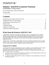
Copper pairs run from the central office (CO) to the customer premises (CP) to create
the local loop. The local loop terminates on the customer premises.
98-15815
RTU
Customer Premises (CP)
Central
Office
(CO)
Local Loop
POTS
Splitter
To End-user
Systems
DSL – Digital Subscriber Line
POTS – Plain Old Telephone Service
RTU – Remote Termination Unit
Network
Service
Provider
(NSP)
POTS
Splitter
POTS
Splitter
NOTES:
— The RTU network performance will depend on the quality and condition of the
phone wiring to and inside the customer premises.
— Telephone is used to represent any equipment that plugs into a phone jack
and uses the POTS phone line, such as a phone, modem, or fax machine.
— A distributed POTS splitter is required for every phone outlet that has
telephone equipment attached.

3
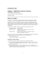
Installing the POTS Splitter Without an RTU
Each POTS splitter connected to a phone without an RTU uses two cables with RJ11
connectors. The two cables are installed:
H From the Local Loop to the POTS splitter (supplied cable)
H From the POTS splitter to the telephone (existing cable)
98-15813
POTS
Splitter
Line from
Local Loop
RJ11 Jack
Telephone
PHONE
LINE DSL
PHONE
LINE DSL
PHONE
LINE DSL
Line from
Local Loop
POTS
Splitter
POTS
Splitter
RJ11 Jack
Telephone
Customer
Premises (CP)
" Procedure
To connect a POTS splitter to a phone without an RTU:
1. Unplug the existing cable from the local loop to the telephone.
2. Plug the existing cable into the POTS splitter jack labeled PHONE.
3. Plug one end of the supplied cable into the POTS splitter jack labeled LINE. Plug
the other end into the line from the local loop.
98-15852
POTS Splitter
Line from Local Loop
(Supplied Cable)
LINE
DSL
PHONE
PHONE
RJ11
Jack
PHONE
LINE
(Existing
Cable)

4
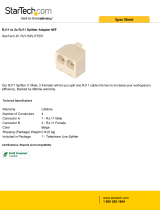
Installing the POTS Splitter With an RTU
The POTS splitter connected to the RTU uses three cables with RJ11 connectors.
The three cables are installed:
H From the Local Loop to the POTS splitter (supplied cable)
H From the POTS splitter to the telephone (existing cable)
H From the POTS splitter to the RADSL RTU (cable supplied with the RTU)
" Procedure
To connect a POTS splitter to a phone and an RTU:
1. Unplug the existing cable from the local loop.
2. Plug the existing cable into the POTS splitter jack labeled PHONE.
3. Plug the end of the cable supplied with the RTU into the POTS splitter jack labeled
DSL. Plug the other end into the RTU jack labeled DSL.
4. Plug the end of the cable supplied with the POTS splitter into the POTS splitter jack
labeled LINE. Plug the other end into the line from the local loop.
98-15812
POTS Splitter
Line from
Local Loop
(Supplied Cable)
DSL
Hotwire RTU
LINE
DSL
PHONE
PHONE
RJ11
Jack
PHONE
LINE DSL
(Existing Cable)

98-15841
Distributed
POTS Splitter
Wall
Fastener
PHONE
LINE DSL
5
Optional Alternative Placement
The POTS splitter is designed for tabletop placement. The POTS splitter can also be
mounted on a wall. To mount a POTS splitter on the wall, you will need:
-
Two #6 self-threading screws with molly bolts for each housing
-
Drill and 3/16″ drill bit for the molly bolt
-
Screwdriver
" Procedure
To mount the POTS splitter:
1. Use a drill to install the plastic anchors.
2. Use a screwdriver to install the screws.
Leave enough clearance for quick removal
of the POTS splitter housing.

6
5038 Distributed POTS Splitter Technical Specifications
Item Specification
*
Height x Width x Depth 1.24″ x 1.87″ x 4.78″ (3.14 cm x 4.75 cm x 12.13 cm)
Weight 3.4 ounces (96.4 grams)
Approvals
FCC Part 68
Safety Certifications
Refer to the equipment’s label for Registration Number.
Refer to the equipment’s label for approvals on product.
Physical Environment
Operating temperature
Storage temperature
Relative humidity
Shock and vibration
32°F to 140°F (0°C to 60°C)
–40°F to 158°F (–40°C to 70°C)
5% to 95% (noncondensing)
Withstands normal shipping and handling
Interface Connectors Three 6-pin, non-keyed RJ11 modular plugs
*
Technical Specifications subject to change without notification.

7
Important Safety Instructions
1. Read and follow all warning notices and instructions marked on the product or
included in the manual.
2. This product is intended to be connected to Listed/Certified telephone wiring with a
minimum of 24 AWG (.5 mm) behind a Listed/Certified primary protector.
3. Do not attempt to service this product yourself, as opening or removing covers may
expose you to dangerous high-voltage points or other risks. Refer all servicing to
qualified service personnel.
4. When installed in the final configuration, the product must comply with the
applicable Safety Standards and regulatory requirements of the country in which it
is installed. If necessary, consult with the appropriate regulatory agencies and
inspection authorities to ensure compliance.
5. In addition, since the equipment is to be used with telecommunications circuits,
take the following precautions:
— Never install telephone wiring during a lightning storm.
— Never install telephone jacks in wet locations unless the jack is specifically
designed for wet locations.
— Never touch uninsulated telephone wires or terminals unless the telephone
line has been disconnected at the network interface.
— Use caution when installing or modifying telephone lines.
— Avoid using a telephone (other than a cordless type) during an electrical storm.
There may be a remote risk of electric shock from lightning.
— Do not use the telephone to report a gas leak in the vicinity of the leak.
Notice to Users of the Telephone Network
This equipment complies with Part 68 of the FCC rules. On the bottom of the
equipment’s enclosure is a label that contains, among other information, the FCC
registration number and ringer equivalence number (REN) for this equipment. If
requested, this information must be provided to the telephone company.
This equipment is designed to be connected to the telephone network or premises
wiring using compatible modular plugs and jacks which are Part 68 compliant. Refer to
Before You Begin
, page 1, for details.
The REN is used to determine the quantity of devices which may be connected to the
telephone line. Excessive RENs on the telephone line may result in the devices not
ringing in response to an incoming call. In most, but not all areas, the sum of RENs
should not exceed five (5.0). To be certain of the number of devices that may be
connected to a line, as determined by the total RENs, contact the local telephone
company.

8
If the Model 5038 Telephone Line Filter causes harm to the telephone network, the
telephone company will notify you in advance that temporary discontinuance of service
may be required. But if advance notice is not practical, the telephone company will
notify the customer as soon as possible. Also, you will be advised of your right to file a
complaint with the FCC if you believe it is necessary.
The telephone company may make changes in its facilities, equipment, operations or
procedures that could affect the operation of the equipment. If this happens, the
telephone company will provide advance notice in order for you to make necessary
modifications to maintain uninterrupted service.
If trouble is experienced with the Telephone Line Filter, for repair or warranty
information, please refer to
Warranty, Sales, and Service Information
.
No repairs may be performed by the end user.
The equipment can not be used on public coin phone service provided by the
telephone company. Connection to party line service is subject to state tariffs. Contact
the state public utility commission, public service commission or corporation
commission for information.
Warranty, Sales, and Service Information
Contact your local sales representative, service representative, or distributor directly for
any help needed. For additional information concerning warranty, sales, service, repair,
installation, documentation, training, distributor locations, or Paradyne worldwide office
locations, use one of the following methods:
Via the Internet: Visit the Paradyne World Wide Web site at:
http://www.paradyne.com
Via Telephone: Call our automated call system to receive current information via
fax or to speak with a company representative.
— Within the U.S.A., call 1-800-870-2221
— Outside the U.S.A., call 1-727-530-2340
*5038–A2–GN10–00*
/