Page is loading ...

TM
1
Hotwire 5546 RTU Customer Premises
Installation Instructions
Document Number 5546-A2-GN10-00
September 1998
Before You Begin
The Hotwire 5546 RTU (Remote Termination Unit) interoperates with the Hotwire
8546 DSL Card in the DSLAM system. Verify that the 8546 DSL card has Firmware
Release 2.2 or higher.
An optional POTS (Plain Old Telephone Service) splitter is available for the Hotwire
5546 RTU. When a POTS splitter is installed, the telephone and 5546 RADSL (Rate
Adaptive Digital Subscriber Line) RTU can function at the same time over the same pair
of copper wires. In order to confirm the RTU installation, the POTS splitter should be
installed first.
To install a POTS splitter, refer to the appropriate POTS splitter document:
Document Number Document Title
5030-A2-GN10
Hotwire 5030 POTS Splitter Customer Premises
Installation Instructions
5038-A2-GN10
Hotwire 5038 Distributed POTS Splitter Customer
Premises Installation Instructions
Contact your sales or service representative to order additional product documentation.
Paradyne documents are also available on the World Wide Web at:
http://www.paradyne.com
Select
Service & Support
→
Technical Manuals
Package Checklist
Verify that your package contains the following:
Model 5546 Remote Termination Unit (RTU)
DSL interface cable with RJ11 connectors
RJ45 to DB9 adapter plug (Part No. 002-0093-0031)
One ferrite choke (Model 5546-A1-200 only)
Power cord with power transformer
Warranty card

2
Wiring and Cables You Need
The following wiring and standard connectors are used with this product:
-
New or existing unshielded twisted-pair wiring (CAT3 or better). The CAT3 wiring
must meet EIA/TIA-568 specifications with 24 AWG (.5 mm) or 26 AWG (.4 mm).
-
DTE EIA-530A to V.35 interface cable (Model No. 3100-F1-570).
-
Straight-through cable with an 8-pin, RJ45, non-keyed modular plug.
-
Standard RJ11 wall jack.
Refer to
Cables & Connectors,
page 15, for cable details.
What Does the Hotwire 5546 RTU Do?
The Hotwire 5546 RTU is a component in the Hotwire DSL Access System. This
system provides high-speed Internet or corporate LAN access over traditional
twisted-pair copper telephone wiring.
A POTS splitter blocks out the DSL signal and allows the POTS frequencies to pass
through. At the customer premises, the RADSL RTU and a telephone can function
simultaneously over the same pair of copper wires when either:
H A Hotwire 5030 POTS Splitter is installed near the demarcation point for all
telephones on the same POTS line as DSL,
or
H A Hotwire 5038 Distributed POTS Filter is installed on each telephone on the same
POTS line as DSL.
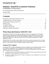
DSL Access with a Hotwire 5030 POTS Splitter
Copper pairs run from the central office (CO) to the customer premises (CP) to create
the local loop. The local loop terminates on the customer premises at the demarcation
point in a punchdown block or network interface device (NID).
When a POTS splitter is used at both ends of the local loop, wiring is connected:
H From the demarcation point to the CP POTS splitter,
H From the demarcation point to the DSL jack.
NOTES:
— End-user system is used to represent any PC connected to a router with an
Ethernet connection and DSL-based service.
— Network Service Provider (NSP) is used to represent any Internet Service
Provider (ISP) or remote LAN access provider.

3
98-15613-0
2
Punchdown
Block or NID
DSL
Jack
RTU
New Wiring Connections Existing Wiring (POTS)
Customer Premises (CP)
DSL
Central
Office
(CO)
Network
Service
Provider
(NSP)
Demarcation
Point
Local Loop
Router
CP
POTS
Splitter
POTS
DSL – Digital Subscriber Line POTS – Plain Old Telephone Service
NID – Network Interface Device RTU – Remote Termination Unit
End-user
Systems
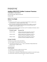
DSL Access with a Hotwire 5038 Distributed POTS Splitter
When a Hotwire 5038 Distributed POTS Splitter is used, one 5038 Distributed POTS
Splitter is installed as a filter for each telephone on the same POTS line as DSL.
98-15815-0
1
RTU
Customer Premises (CP)
Central
Office
(CO)
Local Loop
POTS
Splitter
To End-user
Systems
DSL – Digital Subscriber Line POTS – Plain Old Telephone Service
NID – Network Interface Device RTU – Remote Termination Unit
POTS
Splitter
POTS
Splitter
Network
Service
Provider
(NSP)
Demarcation
Point
Punchdown
Block or NID
POTS/DSL
Optional

4
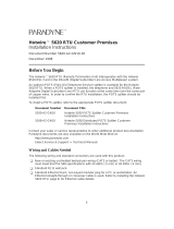
DSL Access without a POTS Splitter
When the Hotwire 5546 RTU is installed without a POTS splitter, a second telephone
wiring pair is needed for DSL access.
98-15614-02
Punchdown
Block or NID
DSL
Jack
RTU
Customer Premises (CP)
POTS
DSL
Central
Office
(CO)
Network
Service
Provider
(NSP)
Demarcation
Point
Local Loop
Router
New Wiring Connections Existing Wiring (POTS)
DSL – Digital Subscriber Line POTS – Plain Old Telephone Service
NID – Network Interface Device RTU – Remote Termination Unit
End-user
Systems

5
Installing the DSL Access Wiring
The local loop terminates at the punchdown block or NID. Wiring must be connected
from the customer premises side of the punchdown block or the NID to an RJ11 wall
jack. Typically, the punchdown block is installed in commercial locations and the NID is
installed in residential locations.
Procedure
1. Access the punchdown block or NID.
!
WARNING:
Do not continue unless the DSL access line from the local loop has been
disconnected at the NID or punchdown block. Refer to
Important Safety
Instructions,
page 18.
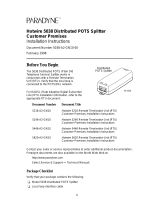
2. Disconnect the DSL access pair from the local loop. A punchdown block is used
without a POTS splitter in the following example.
ABCD
DSL
Access
from Local
Loop
Wiring to
DSL Jack
Bridge Clip
Punchdown Block
97-15348
Demarcation Point
Customer Premises

6
3. Locate the DSL pair of T1/R1 connectors on the the customer premises side of the
NID or punchdown block. Attach the wiring that will be connected to the DSL jack.
In the following example, a NID is used without a POTS splitter. It includes an
existing POTS line and a second pair installed for DSL access.
DSL/POTS
Access from
Local Loop
Wiring to
DSL Jack
Telephone Network Interface Device (NID)
Ground
Tip
T1
(Green)
Ring
R1
(Red)
97-15438-01
Existing POTS
Wiring to
Telephone
Demarcation Point
Customer Premises
DSL Pair
POTS Pair

97-15300a
RJ11 Wall Jack
or
7
The Hotwire 5546 RTU connects to the local loop via wiring from the demarcation point
to an RJ11 wall jack. The DSL twisted-pair wiring from the local loop terminates at a
new or existing wall jack. It may be necessary to install a standard single RJ11 jack or
replace a single jack with a double RJ11 jack.
97-15343-0
2
DSL
RJ11
Jack
Central
Office
Punchdown
Block or NID
Customer Premises
POTS/DSL
Local Loop
Demarcation Point
DSL
Twisted-pair
Wiring
RTU
Procedure
1. Wiring can be run from the
punchdown block or NID to a
new or existing wall jack. Match
the pair colors on both ends.
2. Label the DSL jack.
3. Reconnect the DSL access
pair at the punchdown block
or NID.
The RJ11 6-pin jack uses the center two pins. For pin assignments, refer to
Cables &
Connectors
, page 15.

8
Installing the Hotwire 5546 RTU
Place the Hotwire 5546 RTU on a flat surface with clearance for the rear connectors.
Procedure
1. Use the RJ11 6-pin cable for the DSL connection. Insert one end of the cable into
the jack labeled DSL. Insert the other end into the wall jack labeled DSL.
98-15612-01
DSL
Jack
POWER
CONSOLE
DSL
Hotwire 5546 RTU
DTE
If the Hotwire 5546 RTU is installed on the same line as POTS, a Hotwire 5038
Distributed POTS Splitter can be used as a filter. One 5038 Distributed POTS
splitter is installed as a filter for each telephone as shown below. To install the
5038 Distributed POTS splitter, refer to
Hotwire 5038 Distributed POTS Splitter
Customer Premises Installation Instructions.
98-15813
Distributed
POTS Splitter
Line from
RJ11 Wall Jack
PHONE
LINE DSL
PHONE
LINE DSL
PHONE
LINE DSL
Line from
RJ11 Wall Jack
Distributed
POTS Splitter
Distributed
POTS Splitter
Customer
Premises (CP)
Hotwire
RTU

9
2. The DTE port connection is configurable for EIA-530A or V.35 operation.
Insert the 25-position EIA-530A DTE cable or V.35 adapter cable into the jack
labeled DTE. Tighten both screws on the DTE connector. Insert the other end into
the DTE.
98-15616-01
POWER
DSL
Hotwire 5546 RTU
DTE
CONSOLE
To
DTE
V.35 Adapter
Cable
NOTE:
Use only well-shielded cables, including a braided metal shield and metallic hood.
3. The Console port connection is optional and only necessary to change the DTE
configuration defaults or to download software. This connection can be temporary
and disconnected after the changes are completed. See
Hotwire 5546 RTU
Configuration Setup,
page 12.
The Console port acts as a DCE and uses an 8-pin RJ45 straight-through cable for
the connection to a VT100 terminal or a PC running a terminal emulation program.
Use the supplied DB9 adapter to connect to a PC or laptop.
Insert the 8-pin end of the cable into the jack labeled CONSOLE. Insert the other
end into the DB9 adapter for the serial port of the VT100 terminal or PC.
98-15615-01
Console
Serial Line
POWER
CONSOLE
DSL
Hotwire 5546 RTU
DTE
VT100 Terminal
or PC
(9-pin Adapter)

10
4. Insert the power cord’s round end into the jack labeled POWER. If you do not have
Model 5546-A1-200, proceed to Step 6.
For Model 5546-A1-200 only, place the ferrite choke on the Power cable as closely
as possible to the RTU. Pass the Power cable through the ferrite choke twice,
creating a loop as shown.
98-16130
5. Close the two halves around the cable and snap the ferrite choke shut. Press
down on the plastic latch to secure the ferrite choke in place around the cable.
98-15610-01
POWER
CONSOLE
DSL
Hotwire 5546 RTU
Power
Jack
Transformer
DTE
Required
on
Some Models
6. Plug the transformer into an AC outlet. The RTU hardware setup is now complete.
NOTE:
Use only the transformer provided with this product.

11
Power-On
When power is applied, the RTU performs self-diagnostics and the PWR LED is on.
During the power-on self-test, all of the LEDs turn on for one second.
TST
DSL
DTR
ALMPWR
TM
97-15611
Power – green
Alarm – red
Test – yellow
Digital Subscriber Line – green
Data Terminal Ready – green
5546
Refer to
Troubleshooting,
page 14, for LED indications requiring action.
Status LEDs
After a successful self-test, the LEDs should appear as indicated in BOLD in the
Condition column below.
LED Condition Status
PWR ON RTU has power.
ALM OFF No active alarms.
TST OFF No active tests.
DSL ON The DSL link is now active and ready to transmit and
receive data.
DTR ON The Data Terminal Ready connection to the DTE data
interface is active.

12
Hotwire 5546 RTU Configuration Setup
The Console cable is connected to a VT100-compatible terminal or a PC running a
terminal emulation program. Verify the terminal settings:
Data rate set to 9.6 kbps
Character length set to 8
Parity set to None
Stop bits set to 1
Flow control is Off
When the Console cable is connected, the DTE Configuration screen appears with the
following default settings:
DTE Configuration:
Electrical Interface V35
Local Loopback OFF
TX Timing Source DCE
TX Data Strobe POSITIVE
–––––––––––––––––––––––––––––––––––––––––––––––––––––––––––––––––––––––
HW Model: X Serial No.: X
HW Revision: X FW Version: X
If the DTE Configuration screen does not appear, press Ctrl-l. Use the following
keyboard keys to navigate within the screen:
To . . . Press . . .
Move to the next field Tab key or Down Arrow key.
Move to the previous field Ctrl-k or Up Arrow key.
Toggle between the two valid settings Spacebar.
Redraw the screen Ctrl-l.
Save changes made since the last Return Enter (Return).

13
Configuration Options Table
The DTE Configuration screen provides the following options and settings.
Configuration
Option Field
Settings Description
Electrical Interface V35
EIA530A
V.35 DCE to DTE interface.
EIA-530A DCE to DTE interface.
Local Loopback OFF
ON
Local loopback is not active.
Local loopback is active and the TST LED is
on. Local loopback causes any data
received from the DTE to be returned to the
DTE. The clock is locally generated by the
DCE.
TX Timing Source DTE
DCE
The DTE clock is used for the RTU Transmit
Timing Source.
The DCE generates an internal
synchronous clock for the RTU Transmit
Timing Source.
TX Data Strobe POSITIVE
NEGATIVE
Clocking uses positive edge of clock.
Clock is inverted to use the negative edge of
the clock.
Save configuration option changes by pressing Enter. The message Configuration
Updated appears above HW Model on the bottom left of the screen. The next key
pressed causes the message to disappear.
NOTES:
— The Hotwire 5546 RTU configuration setup is now complete. Disconnect the
Console cable.
— Setting the Electrical Interface option to EIA530A without the proper router
interface connector will result in unexpected errors.

14
Troubleshooting
LED Symptom Action
All LEDs remain on. The RTU is not functional. If the LEDs remain on after five
minutes, contact the NSP.
ALM LED remains
on.
The power-on self-test may have failed. Unplug the unit and
reapply power. If the alarm light is still on, contact the NSP.
ALM and TST
LEDs are on.
Firmware download may be in progress. If the LEDs remain on
after five minutes, contact the NSP.
DSL LED is off. Verify that the DSL cable is securely installed on both ends. If
the problem continues, contact the NSP.
DSL LED continues
to blink after the
power-on self-test.
The RTU is attempting to establish the DSL link or is adjusting
the rate of the DSL line due to line conditions. If the LED
continues to blink for more than five minutes, contact the NSP.
DSL LED is on and
there is no data
transmission.
The DSL link has been established but there is no data
transmission. First, verify the DTR connection. If the problem
persists, contact the NSP.
DSL and DTR
LEDs are on and
there is no data
transmission.
The DSL and DTR links have been established but there is no
data transmission. If the problem persists, contact the NSP.
DSL and DTR
LEDs are off.
Firmware download may be in progress. Verify that the ALM
and TST LEDs are on.
DTR LED is off.
Verify that the DTE cable is securely installed at both ends, and
that the DTE is connected and powered on.
Verify that the correct V.35 or EIA-530A DTE cable is installed.
Refer to
Installing the Hotwire 5546 RTU,
page 8.
PWR LED is off.
Check that the power cord is securely installed on both ends.
If no LEDs are on, the power supply may be defective. Test the
outlet to verify power. If the problem persists, contact the NSP.
If other LEDs are on, the PWR LED may be burned out. Unplug
the unit and reapply power; watch all LEDs during the
power-on self-test to verify that the PWR LED is functioning.
TST LED is on.
A local loopback test may be active. Refer to
Hotwire 5546
RTU Configuration Setup,
page 12.
A test initiated by the NSP may be active. Wait five minutes. If
the TST LED does not go off, contact the NSP.
NOTE:
Firmware download is available via the Console Port. Contact the NSP for details.

98-15304-01
6-Pin
RJ11 Plug
DSL
Cable
Pin #1
Pin #6
97-1567
8
8-Pin
Plug
Console Port
Cable
Pin #1
Pin #8
98-1605
0
DB9
to RJ45
15
Cables & Connectors
Obtain standard twisted-pair CAT3 or better cables.
This section is reference only.
The DSL interface connector uses a 6-pin,
non-keyed modular plug.
RJ11 6-Pin Connector
Pin # Function
1 & 2 Not used
3 DSL Ring
4 DSL Tip
5 & 6 Not used
The Console connector uses an 8-pin RJ45 non-keyed modular plug and DB9
adapter. Only use this connection when the DTE Configuration defaults need to be
changed. See
Hotwire 5546 RTU Configuration Setup,
page 12.
RJ45 8-Pin Connector
Pin # Circuit Direction
1 Not used —
2 DTR Input
3 TXD Input
4 Signal Ground —
5 Signal Ground —
6 RXD Output
7 DSR Output
8 Not used —
DB9 Adapter Plug
(Supplied)

16
The DTE connector uses a 25-position D-subminiature plug. The following table
provides the pin assignments for the EIA-530A and the V.35 connector to the RTU.
Signals that are not listed are not supported.
DB25 DTE Port Connector Pin Assignments
Signal Name
DB25
Plug
Signal Direction
MS34
Socket
Shield 1 —
Transmitted Data (TxD+) 2 To RTU (In) P
Received Data (RxD+) 3 From RTU (Out) R
Request to Send (RTS+) 4 To RTU (In) C
Clear to Send (CTS+) 5 From RTU (Out) D
DCE Ready (DSR) 6 From RTU (Out) E
Signal Ground (SG) 7 — B
Received Line Signal Detector (DCD+) 8 From RTU (Out) F
Receiver Timing DTE (RxC–) 9 To RTU (In) X
Received Line Signal Detector (DCD–) 10 From RTU (Out) —
Transmit Timing DTE (TxCE+) 11 To RTU (In) W
Transmitter Timing DCE (TxC–) 12 From RTU (Out) AA
Clear to Send (CTS–) 13 From RTU (Out) —
Transmitted Data (TxD–) 14 To RTU (In) S
Transmitter Timing DCE (TxC+) 15 From RTU (Out) Y
Received Data (RxD–) 16 From RTU (Out) T
Receiver Timing DCE (RxC+) 17 From RTU (Out) V
Local Loopback (LL) 18 To RTU (In) N
Request to Send (RTS–) 19 From RTU (Out) —
DTE Ready (DTR) 20 To RTU (In) H
Transmit Timing DTE (TxCE+) 24 To RTU (In) U
Test Mode (TM) 25 From RTU (Out) NN

17
The EIA-530A-to-V.35 Adapter Cable provides the V.35 interface shown below.
The V.35 cable includes a 25-pin to 34-pin adapter.
98-16045
Pin 1
DB25
Pin A
Pin NN
MS34

18
Model 5546 RTU Technical Specifications
Item Specification*
Height x Width x Depth
1.43″ x 6.00″ x 8.75″ (3.64 cm x 15.24 cm x 22.23 cm)
Weight 1 lb. 1 oz. (0.48 kg)
Power
Class 2 Transformer normal
service input voltage range
Input: 100 Vac (+10%), 50 Hz;
120 Vac (+10%), 60 Hz; or
230 Vac (+
10%), 50/60 Hz
Output: 15 Vdc nominal, 0.6A
Approvals
FCC Part 15
CISPR 22
Safety Certifications
Class B Subpart B digital device
Class A
Refer to equipment’s label for approvals on product
Physical Environment
Operating temperature
Storage temperature
Relative humidity
Shock and vibration
32°F to 140°F (0°C to 40°C)
–4°F to 158°F (–20°C to 70°C)
5% to 95% (noncondensing)
Withstands normal shipping and handling
Heat Dissipation 25.0 Btu/hr. (max.) at nominal input voltage
Interface Connectors
DSL Interface
RJ11 6-pin
DSL Interface
Console Interface
DTE Interface
RJ11 6 pin
RJ45 8-pin
D-subminiature 25-pin
*Technical Specifications subject to change without notification.

19
Important Safety Instructions
1. Read and follow all warning notices and instructions marked on the product or
included in the manual.
2. Slots and openings in the cabinet are provided for ventilation. To ensure reliable
operation of the product and to protect it from overheating, these slots and
openings must not be blocked or covered.
3. Do not allow anything to rest on the power cord and do not locate the product
where persons will walk on the power cord.
4. Do not attempt to service this product yourself, as opening or removing covers
may expose you to dangerous high voltage points or other risks. Refer all servicing
to qualified service personnel.
5. General purpose cables are used with this product for connection to the network.
Special cables, which may be required by the regulatory inspection authority for
the installation site, are the responsibility of the customer. Use a UL Listed, CSA
certified, minimum No. 24 AWG line cord for connection to the Digital Subscriber
Line (DSL) network.
6. When installed in the final configuration, the product must comply with the
applicable Safety Standards and regulatory requirements of the country in which it
is installed. If necessary, consult with the appropriate regulatory agencies and
inspection authorities to ensure compliance.
7. A rare phenomenon can create a voltage potential between the earth grounds of
two or more buildings. If products installed in separate buildings are
interconnected, the voltage potential may cause a hazardous condition. Consult a
qualified electrical consultant to determine whether or not this phenomenon exists
and, if necessary, implement corrective action prior to interconnecting the products.
8. Input power to this product must be provided by one of the following: (1) a UL
Listed/CSA certified power source with a Class 2 or Limited Power Source (LPS)
output for use in North America, or (2) a certified transformer, with a Safety Extra
Low Voltage (SELV) output having a maximum 240 VA available, for use in the
country of installation.
9. In addition, since the equipment is to be used with telecommunications circuits,
take the following precautions:
— Never install telephone wiring during a lightning storm.
— Never install telephone jacks in wet locations unless the jack is specifically
designed for wet locations.
— Never touch uninsulated telephone wires or terminals unless the telephone
line has been disconnected at the network interface.
— Use caution when installing or modifying telephone lines.
— Avoid using a telephone (other than a cordless type) during an electrical
storm. There may be a remote risk of electric shock from lightning.
— Do not use the telephone to report a gas leak in the vicinity of the leak.

20
CE Marking
When the product is marked with the CE mark on the equipment label, this
demonstrates full compliance with the following European Directives:
Directive 73/23/EEC – Council Directive of 19 February 1973 on the
harmonization of the laws of the member states relating to electrical equipment
designed for use within states relating to electrical equipment designed for use
within certain voltage limits, as amended by Directive 93/68/EEC.
Directive 89/336/EEC – Council Directive of 3 May 1989 on the approximation of
the laws of the member states relating to Electro-Magnetic Compatibility (EMC), as
amended by Directive 93/68/EEC.
Japan
Class 1 ITE
This is a Class 1 product based on the standard of the Voluntary Control Council for
interference by Information Technology Equipment (VCCI). If this equipment is used in
a domestic environment, radio disturbance may arise. When such trouble occurs, the
user may be required to take corrective actions.
/