Page is loading ...

ARIESAUTOMOTIVE.COM
•
NEED ASSISTANCE?
•
877.287.8 634
•
P1055-INS-RA
•
PAGE 1
INSTALLATION MANUAL
P1055
Parts List
1 Pro Series grille guard
1 Driver / left mounting bracket
1 Passenger / right mounting bracket
1 Driver / left top bracket
1 Passenger / right top bracket
1 Driver / left light mount bracket
1 Passenger / right light mount bracket
1 Support flange
2 Hex bolt, M6
4 Flat washer, M6
2 Nylock nut, M6
2 Hex bolt, M8
2 Button head bolt, M8
2 Clip nut, M8
4 Flat washer, M8
4 Lock washer, M8
4 Button head bolt, M10
4 Nylon lock nut, M10
8 Flat washer, M10
1 Allen wrench, 5mm
1 Allen wrench, 6mm
Level of Difficulty
Easy
Brackets and Hardware
Tools Required
Socket set Wrench set
Ratchet --
Product Photo
Support flange
Passenger / right
top bracket
Passenger / right
frame mounting bracket
Driver / left
top bracket
Driver / left
frame mounting bracket

ARIESAUTOMOTIVE.COM
•
NEED ASSISTANCE?
•
877.287.8 634
•
P1055-INS-RA
•
PAGE 2
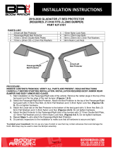
Step 3 - Light Bar Installation
Place the grille guard face down and
set the support flange into the center
flange of the grille guard.
Attach each side of the support flange to the
inner brackets on the center flange with two
M8 hex bolts, flat washers and lock washers.
Snug the hardware,
but do not fully tighten.
Step 1 - Light Bar Installation
Select an LED light (sold separately), mounting
hardware and brackets. Attach the hardware to
the support flange.
Note: LED manufactures may have different
mounting styles or brackets. Once the
mounting options are determined, attach it to
the support flange.
Step 2 - Light Bar Installation
With the LED light attached to
the support flange, place the two
M8 nut clips into the slotted holes
on either side of the support flange.
Torque Specifications
Metric
M6 bolt 3 ft-lbs.
M8 bolt 7 ft-lbs.
M10 bolt 16 ft-lbs.
M12 bolt 28 ft-lbs.
SAE
1/4" bolt 3 ft-lbs.
5/16" bolt 7 ft-lbs.
3/8" bolt 16 ft-lbs.
7/16" bolt 20 ft-lbs.
1/2" bolt 28 ft-lbs.
Use above torque setting unless otherwise noted
Notes and Maintenance
Before you begin installation, read all instructions thoroughly.
Proper tools will improve the quality of installation and reduce the time required.
To protect the product, wax after installing. Regular waxing is recommended
to add a protective layer over the finish. Do not use any type of polish or wax
that may contain abrasives that could damage the finish.
For polished, gloss and other smooth finishes,
polish may be used to clear small scratches and scuffs on the finish.
Mild automotive detergent may be used to clean the product. Do not use dish detergent, abrasive
cleaners, abrasive pads, wire brushes or other similar products that may damage the finish.
Refer to the last page of this manual for
warranty and product registration information.
Refer to the table to the left when securing hardware during the
installation process to help prevent damage to the product or vehicle.
If you are not installing a light bar, proceed to page 3
M8 clip-nut attached,
one per side
LED light
M8 fastener
Support flange

ARIESAUTOMOTIVE.COM
•
NEED ASSISTANCE?
•
877.287.8 634
•
P1055-INS-RA
•
PAGE 3
PROCEDURE:
REMOVE CONTENTS FROM BOX. VERIFY ALL PARTS ARE PRESENT. READ INSTRUCTIONS
CAREFULLY BEFORE STARTING INSTALLATION. CUTTING MAY BE REQUIRED. ASSISTANCE IS
HIGHLY RECOMMENDED.
1. Open the hood and remove the hardware attaching the top of the grille to the radiator core support,
(Figure 1). Next, remove the hardware attaching the bottom of the plastic front bumper cover to the
crossmember under the radiator, (Figure 2). IMPORT
ANT: Pay close attention to the type and location
of all factory hardware for easier reinstallation.
VERY IMPORTANT: This Grille Guard is not compatible with optional Forward Collision
Warning Systems featuring bumper mounted radar controlled sensor. Installation also
excludes all models with factory installed front tow hooks.
2. Move to the driver/left side front wheel opening. Remove the hardware attaching the end of the plastic
lower bumper cover to the inner fender liner, (Figure 3). Pull back the fender liner and unplug the lights
mounted in the bumper.
3.
Carefully pull the forward end of the plastic fender flare straight out to release from clips attaching the
flare to the lower bumper cover and front fender, (Figure 4). VERY IMPORTANT: The plastic clips
attaching the flare to the bumper and fender are fragile. Use of an automotive panel removal tool, (not
included), is highly recommended to prevent damage to inner clips. Do not remove the flare, only
release the forward end of
the flare to allow access to the (4) screws under the flare. Remove the
screws attaching the end of the bumper to forward end of the fender. Repeat this Step to loosen the
passenger/right side of the bumper cover, (Figure 5).
4. Once all hardware has been removed, with assistance, pull the bumper and grill assembly straight out
and off of the vehicle and place on a clean surface, (Figure 5).
5. Move to the driver/left side of the aluminum
inner impact bumper. Locate the factory hex bolts attaching
the top of the inner impact bumper to the vehicle. Remove the inner hex bolt only, (Figure 6). Do not
remove the outer bumper bracket bolt. Select the driver/left Top Mounting Bracket, (Figure 7). Hold the
Bracket in place and mark the outline of the Bracket onto the plastic air deflector, (Figure 8). Remove
the Top Bracket. Cut a small section out of the plastic inner air d
eflector to clear the Top Bracket.
Reuse the factory hex bolt to attach the Top Bracket to the inner bumper bracket, (Figure 9). Snug but
do not fully tighten hex bolt.
6. Next, select the driver/left Frame Mounting Bracket, (Figure 12). Locate and remove the (2) hex bolts
from the bottom of the impact bumper bracket. Reuse the (2) factory hex bolts to attach the Mounting
Bracket to the bottom of the bumper bracket, (Figure 13). Snug but do not
fully tighten hex bolts.
7. Repeat Steps 5—6 to attach the passenger/right Brackets.
8. With assistance, hold the Grille Guard up to the outside of the Mounting Brackets. Attach the Grille
Guard to the Frame Mounting Brackets with the included (4) 10mm Button Head Hex Bolts, (8) 10mm
Flat Washers and (4) 10mm Nylon Lock Nuts, (Figure 14). Attach the Top Brackets to the Grill
Guard with the included (2) 8mm Button Head Hex Bolts, (4) 8mm Flat Wa
shers and (2) 8mm
Lock washers (Figure 15).
9. Align the Grille Guard to the vehicle, check for level, adjust as necessary and fully tighten all hardware
attaching Brackets to the vehicle. Only tighten mounting hardware to vehicle.
IMPORTANT: Slots in Mounting Brackets allow for some
adjustment, but Brackets cannot be adjusted once plastic bumper cover is reinstalled. Make sure Grille
Guard is in correct position and fully tighten hardware attaching Br
ackets to vehicle before removing
Grille Guard.
10. Remove the plastic fill panels blocking the openings in the lower part of the plastic bumper cover,
(Figure 16).
11. With assistance, carefully slide the bumper and grille over the Mounting Brackets, (Figure 17). NOTE:
Use removable tape, (masking tape for example), to cover any sharp edges on the Grille Guard
Brackets to protect the plastic bumper cover from damage during reinstallation.
12. Reu
se the factory hardware to reinstall the plastic bumper cover and grille. Plug in the lights and
reattach the ends of the bumper cover to the bottom of the fenders.
13. Reinstall the Grille Guard (Figures 18, 19 A& 19B). Align and adjust the
Grille Guard and tighten all hardware.
14. Do periodic inspections to the installation to make sure that all hardware is secure and tight.

ARIESAUTOMOTIVE.COM
•
NEED ASSISTANCE?
•
877.287.8 634
•
P1055-INS-RA
•
PAGE 4
Driver Side Installation Pictured
Remove hardware attaching the top of the grille
to the radiator core support. Remove the
hardware attaching the bottom of the bumper
cover to the bottom of the radiator core support.
(Fig 4) Use panel tool (not included) to release
plastic clips. Carefully pull fender flare
straight out to access (4) screws attaching
bumper cover to fender.
Front
(Fig 3) Remove hardware attaching fender to fender
liner. Pull back liner to access and unplug lights
Pull
Fig 1
(Fig 2) Bottom of bumper cover pictured
Front
Front

ARIESAUTOMOTIVE.COM
•
NEED ASSISTANCE?
•
877.287.8 634
•
P1055-INS-RA
•
PAGE 5
Driver Side Installation Pictured
Front
(Fig 5) With assistance, carefully pull
bumper cover and grille assembly off of
vehicle (passenger/right side pictured)
(Fig 7) Driver/left Top Bracket
(Fig 8) Remove hex bolt (large arrow). Select
the driver/left Top Mounting Bracket. Hold
Bracket in position to determine area to cut
from plastic air deflector (white dashed line)
(Fig 6) Driver/left impact bumper bracket
(Fig 9) Reuse factory hex bolt (arrow) to attach
driver/left Top Bracket to bumper bracket

ARIESAUTOMOTIVE.COM
•
NEED ASSISTANCE?
•
877.287.8 634
•
P1055-INS-RA
•
PAGE 6
Driver Side Installation Pictured
(Fig 12) Driver/left Frame Mounting Bracket
Front
Front
(Fig 13) Reuse (2) factory hex bolts
(arrow) to attach driver/left Frame
Bracket to bottom of bumper bracket
(Fig 14) Temporarily attach
Grille Guard to Frame Brackets
(2) 10mm x 35mm Button Head Bolts
(4) 10mm Flat Washers
(2) 10mm Nylon Lock Nuts
Front
(1) 8mm button head bolt
(1) 8mm flat washer
(1) 8mm lock washer

ARIESAUTOMOTIVE.COM
•
NEED ASSISTANCE?
•
877.287.8 634
•
P1055-INS-RA
•
PAGE 7
Driver Side Installation Pictured
(Fig 16) Remove both block offs from bumper
(arrow). NOTE: Pictured from behind bumper
Front
(Fig 17) Before reinstalling the bumper
cover/grille, cover edges on brackets with
removable tape (masking tape for example).
Carefully guide bumper cover/grille assembly
over the bumper brackets and back into position.
(Fig 19A) Reinstall the Grille Guard
Front
Front
(Fig 18) Reinstall Top Support Brackets

ARIESAUTOMOTIVE.COM
•
NEED ASSISTANCE?
•
877.287.8 634
•
P1055-INS-RA
•
PAGE 8
Driver Side Installation Pictured
Front
(Fig 19B) Reinstall the Grille Guard
(2) 10mm Button Head Bolts
(4) 10mm Flat Washers
(2) 10mm Nylon Lock Nuts
Product Registration
CURT Group stands behind our products with industry leading warranties.
You can help us continue to improve our product line and help us understand
your needs by registering your purchase by visiting:
warranty.curtgroup.com/surveys
At CURT Group, customer is king. We value your feedback and we use that information to make
improvements on our products. Please, take a minute and let us know how we are doing.
/