Page is loading ...

Superior Liquid Cooling Systems
®
English v1.0
www.koolance.com
ISO
9001
Printed in Korea
CTR-KSM100
User’s Manual
CTR-KSM100
User’s Manual

1
User Manual
1
A newer version of this User Manual may exist. Please be sure to check our support page
for the latest version of this guide: www.koolance.com
GENERAL PRECAUTION
Please read this manual carefully before beginning the installation of your Koolance
system.
PROHIBITED USE
This product is designed, developed and manufactured as contemplated for general use,
including without limitation: general oce use, personal use and household use, but is not
designed, developed and manufactured as contemplated for use accompanying fatal risks or
dangers that, unless extremely high safety is secured, could lead directly to death, personal
injury, severe physical damage or other loss, including without limitation: nuclear power core
control, airplane control, air trac control, mass transport operation control, life support,
or weapon launching control. If these products are used in such hazardous environments,
Koolance Incorporated does not warrant them.
TRADEMARKS
The Koolance name and logo are trademarks or registered trademarks of Koolance, Inc.
Other company and product names used in this publication are for identication purposes
only and may be trademarks or registered trademarks of their respective companies.
COPYRIGHT
All rights reserved. Copyright (C) Koolance Incorporated.
!
WARNING: Indicates a potentially hazardous situation which, if not avoided,
could result in personal injury or be life-threatening.
!
CAUTION: Indicates a potentially hazardous situation which, if not avoided,
may result in damage to equipment or property.
PROHIBITED: Indicates a prohibited action.
ABOUT SIGNS
Throughout this document, critical information is highlighted in gray-colored boxes. The
following symbols are intended to help prevent any situation which may cause personal
injury and/or damage to equipment:

3
2
User Manual
Table of Contents
Product Diagram ............................................................................................. 4
Connecting Devices ........................................................................................ 5
Display Panel .................................................................................................. 6
Temp/Fan Set .................................................................................................. 7
Alarm Set ........................................................................................................ 8
Relay Set ........................................................................................................ 8
Pump Set ........................................................................................................ 8
Flow Set .......................................................................................................... 8
Display Set ...................................................................................................... 9
Troubleshooting ............................................................................................ 10
Limited Warranty ........................................................................................... 11
CAUTION: Supply only the proper input voltage and polarity to the
product, as labeled below the terminals on the unit. Improper power
can damage the unit and is not covered under the warranty.
!
CAUTION: Do not power 12V pump using the 24V maximum jumper
setting. This can permanently damage the pump and/or the product
and is not covered under the warranty.
!
KOOLANCE CONTACT INFORMATION
Koolance Inc. (USA)
Address: 2840 W. Valley Hwy. N., Ste. 101, Auburn, WA 98001, USA
Telephone: +01 253-249-7669
Technical Support: [email protected]
WARNING: To avoid the risk of electrical shock, do not touch exposed
power terminals on this product or its power supply.
!

5
4
User Manual
4
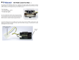
Product Diagram
Fan Extension Wires (x4)
Flow Meter
(INS-FM14/17/18/19)
USB
Port
Thermocouples
(x2)
Trigger Relay
12VDC Input
Power
Pump Extension
Wires (x1)
Thermistor
(x1)
Flow Meter
(INS-FM16)
INS-FM16 LED
Reservoir IR
Level Sensor
Reservoir Float
Level Sensor
Pump (x1)
12V/24V
Pump Output
Jumper
Fans (x4)
Connecting Devices
CTR-KSM100 can power and/or monitor multiple cooling system devices. These
are not included with the CTR-KSM100 controller:
• Fans: 4 extension wires are provided for 3-pin fans. Each connector supports
12VDC up to 2A. Multiple fans can be connected to one plug, provided they
are cumulatively below the amperage limit. It is not recommended to splice
multiple fans to the “RPM” plug, which reports fan speed to CTR-KSM100.
• Pump: Three dierent connectors (two on extensions, one on the main board)
are provided for powering one 12V (max 36W) or 24V (max 50W) DC pump.
Powering multiple pumps is not supported.
• Temperature Sensors: One Koolance 10K-ohm thermistor, and up to two
K-type thermocouples are supported.
• Flow Meter: One Koolance ow meter can be connected to the unit. Models
INS-FM14, INS-FM16, INS-FM17/N, INS-FM18, INS-FM19, and
SEN-FM18T10 are supported.
• Coolant Level Sensor: One Koolance reservoir level sensor can be connected
to the unit. Models SEN-LVL70 and SEN-LVLIR01 are supported. (Models
SEN2-LVL70 and SEN2-LVL100 can be connected, but only one level point
is monitored.)
Power Terminals
CTR-KSM100 requires 12VDC input power from a power
supply with enough amperage to power all connected
devices. For applications up to 8-Amps, Koolance model
PSU-ALX12V power supply can be used.
Attach the included power terminals from the DC power
supply to the -/+ labeled terminals. DO NOT REVERSE THE
POLARITY, or damage to the CTR-KSM100 could result.
Negative
(-)
Positive
(+)
CTR-KSM100 must be opened
temporarily to connect power
terminals and certain devices.
Remove the screws circled on the
right. Then slide back the cover,
and lift up to remove it. Device
cables should exit together at the
rear grommeted opening.

7
6
User Manual
Display Panel
The Koolance display panel allows control and monitoring of various aspects of
the cooling unit. 5 buttons are used, with directional arrows to navigate or change
settings, and a center button to select/exit.
Navigate Up,
Increase Setting
Navigate Down,
Decrease Setting
Navigate
Left
Navigate
Right
Enter/Exit
◙
Software Control
This unit supports Koolance’s “System Monitor” application for device control,
viewing, and logging data to a computer le. Visit www.koolance.com/software to
download the latest version of the program. Consult the application’s readme.txt
for details on usage. Software features requires the USB port be connected to a
computer running Windows 10.
• On the main screen, hold
◙ for 3 seconds to change display units between
°C/°F and LPM/GPM.
12V/24V Pump Jumper
Select between a maximum pump output voltage of 12VDC or
24VDC by moving the indicated jumper. ONLY USE A VOLTAGE
SUPPORTED BY THE CONNECTED PUMP, or damage can occur.
External Sensors
Up to two K-type thermocouples and one Koolance
10K Ohm thermistor (sensors not included) can be
used for temperature monitoring, alarm, and relay
options. For thermocouples, follow the polarity
marked on the board.
Thermocouples
(x2)
Thermistor
(x1)
TEMP/FAN SET
Under “TEMP/FAN SET”, you can select an active set-point temperature the
controller will attempt to follow by way of automatically adjusting fan speed. It is
also possible to keep the fans at a xed power level. There are four options to
select from. Press ▼ and ▲ to scroll among them:
LIQ TEMP: Thermistor Temperature (Range: -30 to 90°C)
CH1 TEMP: Thermocouple #1 Temperature (Range: -20 to 120°C)
CH2 TEMP: Thermocouple #2 Temperature (Range: -20 to 120°C)
FAN PWR: Static fan power setting (Range: 0 to 100%)
The sensor currently displayed in this menu is what the unit will follow. Only
one can be active. Press ◙ to adjust the target value using ▼ and ▲. Below are
some examples:
LIQ TEMP= 32C Maintain thermistor sensor at 32°C
CH1 TEMP= 50C Maintain the rst thermocouple at 50°C
CH2 TEMP= -5C Maintain the second thermocouple at -5°C.
FAN PWR= 45% Keep fans at 45% power, regardless of temperature.
Press ◙ again to exit conguration of the sensor. Press ◄ to return to the previous
menu.
▲
▼
Main Menu
To enter the main menu, briey press ◙. The selected option will begin ashing.
Use ▼ and ▲ to navigate this menu.
TEMP/FAN SET: Temperature set-point and fan settings
ALARM SET: Alarm settings
RELAY SET: Relay Trigger settings
PUMP SET: Pump speed settings
FLOW SET: Flow meter settings
DISPLAY SET: LED display settings
When in the top menu, press ◙ to enter one of the above categories. To exit from
here and most subcategories, press ◄.
▲
▼
12V
Max
24V
Max
• You can exit any menu and return to the main screen by holding ◙ for 2
seconds.
• To reset ALL settings to default, hold ▼ + ▲ for 3 seconds.
To power on the unit, ip the front power switch.

9
8
User Manual
RELAY SET
Terminals are provided for a congurable relay. Wires can be
connected as normally-open (NO), or normally-closed (NC), labeled
near the terminals. Either option will use one wire on common (COM).
There are ve options which are simultaneously active. Upon
entering the relay menu, the last edited value will ash. Press ▼
or ▲ to adjust this value. Press ◙ to edit the value, and again
to return to the previous menu. To disable the relay, increase or decrease its
setting to “ -- ”.
LIQ TEMP: Thermistor Temperature (Range: 0 to 99°C)
CH1 TEMP: Thermocouple #1 Temperature (Range: 0 to 99°C)
CH2 TEMP: Thermocouple #2 Temperature (Range: 0 to 99°C)
FAN: Fan Tachometer (Range: 100 to 10,000RPM)
PUMP: Pump Tachometer (Range: 100 to 10,000LPM)
FLOW: Coolant Flow Rate (Range: 0.1 to 10.0LPM)
LEVEL: Low Coolant Level in Reservoir (ON, or OFF to disable)
PUMP SET
The pump speed can be manually set from 1 (lowest) to 10 (highest):
PUMP(1-10) 7LV : Pump Speed Level
The pump speed level will ash. Press ▼ or ▲ to adjust. Press ◙ to return to the
previous menu.
ALARM SET
This menu aects when the built-in audio alarm will sound. There are ve options
which are simultaneously active. Upon entering the alarm menu, the last edited line
will ash. Press ▼ or ▲ to change it. Press ◙ to edit the value, and again to return
to the previous menu. To disable an alarm, increase or decrease its setting to “ -- ”.
LIQ TEMP: Thermistor Temperature (Range: 0 to 99°C)
CH1 TEMP: Thermocouple #1 Temperature (Range: 0 to 99°C)
CH2 TEMP: Thermocouple #2 Temperature (Range: 0 to 99°C)
FAN: Fan Tachometer (Range: 100 to 10,000RPM)
PUMP: Pump Tachometer (Range: 100 to 10,000LPM)
FLOW: Coolant Flow Rate (Range: 0.1 to 10.0LPM)
LEVEL: Low Coolant Level in Reservoir (ON, or OFF to disable)
▲
▼
▲
▼
If “CYCLIC” is chosen from the DISPLAY SET menu, multiple values can be rotated
through the front display.
The rst line will ash. Use ▼ and ▲ to navigate to other lines. Press ◙ to enable
or disable each value. This will remove the asterisk, thereby hiding that line from
being shown on the main screen:
*FAN SET : (Field varies) Shows current active set-point or fan power
*LIQ TEMP : Shows reservoir liquid temperature
CH1 TEMP : Shows rst external sensor temperature (if connected)
CH2 TEMP : Shows second external sensor temperature (if connected)
FAN : Shows radiator fan RPM
*PUMP : Shows pump impeller RPM
*FLOW : Shows liquid ow rate through the unit
Press ◄ to return to the previous menu, or press ► to exit DISPLAY SET.
▲
▼
The rst line will ash. Press ▼ or ▲ to change what this line will display:
FAN SET : (Field varies) Shows current active set-point or fan power
LIQ TEMP : Shows thermistor temperature sensor
CH1 TEMP : Shows rst thermocouple temperature sensor
CH2 TEMP : Shows second thermocouple temperature sensor
FAN : Shows radiator fan RPM
PUMP : Shows pump impeller RPM
FLOW : Shows liquid ow rate through the unit
Press ◙ to move to line 2, and similarly use ▼ or ▲ to choose what will be
displayed on the second line. Press ◙ again to exit.
▲
▼
DISPLAY SET
The display settings congure which values you wish to appear on the front display
and how they are shown:
DISPLAY
FIXED CYCLIC : Show 2 xed values or cycle multiple values
Congures the unit for an attached Koolance ow meter model:
FM-(14/16/17/18/19): ow meter model number
ID:6/10/13mm: Internal tubing diameter attached to the ow meter
The pump speed level will ash. Press ▼ or ▲ to adjust. Press ◙ to return to the
previous menu.
FLOW SET

11
10
User Manual
We hope your Koolance product will provide you with years of reliable performance.
To help avoid unnecessary RMA issues, we have prepared this list of possible
operational problems, and their most common solutions.
1. The fan says “0RPM”
This product can only read the motor speed for one fan connected to the cable
marked “FAN (RPM)”. The tachometer must be an open collector type. Do not
connect more than one tachometer to this plug, or the value can be incorrect.
2. The pump says “0RPM”
This product can only read the motor speed for one pump using an open col-
lector tachometer. Do not connect more than one pump.
3. The alarm sounds and I’m not sure why...
The oending device and value will ash in the front display whenever an alarm
sounds. Check that your alarm is congured as desired (see “ALARM SET”).
If the unit is otherwise working properly, try resetting all controller settings by
holding ▼ + ▲ for a few seconds until 3 beeps are heard.
4. The front display is locked up or not responding.
Reset all settings by holding ▼ + ▲ for a few seconds until 3 beeps are
heard. After a reset, all conguration settings (alarm, pump, relay, etc.) must
be updated again.
5. LIQ TEMP says “OPEN”.
A Koolance 10K Ohm thermocouple is not connected, defective, or is not the
expected type of thermocouple. Try reconnecting or replacing the sensor.
6. CH1 or CH2 says “----”.
A K-type thermocouple is not connected or might be defective. Try reconnecting
the wires to the terminals, or replace the sensor.
Troubleshooting
Limited Warranty
Disclaimer
Koolance Incorporated (“Koolance”) warrants each new Koolance liquid-cooled
system (“the system”), against defects in materials or workmanship for a period of
one year from the date of purchase, and agrees to repair or replace any defective
Koolance system without charge. Shipping costs are non-refundable.
This warranty is non-transferable. All warranty claims must be accompanied by the original
proof of purchase.
THIS WARRANTY DOES NOT COVER DAMAGE RESULTING FROM ACCIDENT,
MISUSE OR ABUSE, LACK OF REASONABLE CARE, SHIPPING DAMAGE,
MODIFICATIONS, THE AFFIXING OF ANY ATTACHMENT NOT PROVIDED WITH
THE PRODUCT, LOSS OF PARTS, OR OPERATING COMPONENTS AT SPEEDS OR
FUNCTIONS OTHER THAN THOSE SPECIFIED BY THEIR MANUFACTURERS.
Use of unauthorized replacement parts or liquids will void this warranty. Koolance
Incorporated will not pay for warranty service performed by a non-authorized repair
or diagnostic service and will not reimburse the consumer for damage resulting from
warranty service performed by a non-authorized repair service. No responsibility is
assumed for any special incidental or consequential damages due to a defective Koolance
product.
In order to obtain warranty service, contact our RMA department for information. The
product must be shipped postage prepaid to an authorized Koolance service location. It
is suggested that, for your protection, you return shipments of product by insured mail,
insurance prepaid. Damage occurring during shipment is not covered by this warranty.
Shipping costs are non-refundable. No other warranty, written or oral, is authorized by
Koolance Incorporated.
IN NO EVENT SHALL KOOLANCE INCORPORATED OR ITS EMPLOYEES, AGENTS,
SUPPLIERS, MANUFACTURERS, OR CONTRACTORS BE LIABLE FOR ANY
DAMAGES OF ANY KIND OR CHARACTER, INCLUDING WITHOUT LIMITATION
ANY COMPENSATORY, INCIDENTAL, DIRECT, INDIRECT, SPECIAL, PUNITIVE, OR
CONSEQUENTIAL DAMAGES, LOSS OF USE, LOSS OF DATA, LOSS OF INCOME OR
PROFIT, LOSS OF OR DAMAGE TO PERSONS OR PROPERTY, CLAIMS OF THIRD
PARTIES, OR OTHER LOSSES OF ANY KIND OR CHARACTER, AND WHETHER
OR NOT THE POSSIBILITY OF SUCH LOSS OR DAMAGE HAS BEEN NOTIFIED TO
KOOLANCE INCORPORATED.
/