Page is loading ...

t
v
tmax
t
v
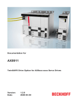
STO SS1
SY6 safety module
Manual
en-US
03/2020
ID 442744.03

Table of contents STOBER
ii
03/2020 | ID 442744.03
Table of contents
1 Foreword .................................................................................................................................................................. 5
2 User information ....................................................................................................................................................... 6
2.1 Storage and transfer ................................................................................................................................................ 6
2.2 Described product.................................................................................................................................................... 6
2.3 Timeliness ................................................................................................................................................................ 6
2.4 Original language ..................................................................................................................................................... 6
2.5 Limitation of liability ................................................................................................................................................ 6
2.6 Formatting conventions........................................................................................................................................... 7
2.6.1 Use of symbols........................................................................................................................................ 7
2.6.2 Markup of text elements ........................................................................................................................ 8
2.6.3 Mathematics and formulas..................................................................................................................... 8
2.7 Trademarks .............................................................................................................................................................. 9
3 General safety instructions...................................................................................................................................... 10
3.1 Standards ............................................................................................................................................................... 10
3.2 Qualified personnel................................................................................................................................................ 10
3.3 Intended use ..........................................................................................................................................................11
3.4 Decommissioning................................................................................................................................................... 11
4 Safety module SY6................................................................................................................................................... 12
5 System design and function..................................................................................................................................... 13
6 Technical data ......................................................................................................................................................... 15
7 What you should know before commissioning ........................................................................................................ 16
7.1 Program interfaces................................................................................................................................................. 16
7.1.1 DS6: Structure of the program interface .............................................................................................. 16
7.1.2 TwinCAT 3: Structure of the program interface.................................................................................... 17
7.2 Power-loss protected storage................................................................................................................................ 17
8 Commissioning ........................................................................................................................................................ 18
8.1 SY6: Assigning the FSoE address ............................................................................................................................18
8.2 Recommended time settings ................................................................................................................................. 19
8.3 DS6: Configuring the drive controller .................................................................................................................... 20
8.3.1 Initiating the project ............................................................................................................................. 20
8.3.2 Parameterizing general EtherCAT settings ........................................................................................... 21
8.3.3 Configuring PDO transmission .............................................................................................................. 22
8.3.4 Transmitting and saving the configuration........................................................................................... 23
8.3.5 Creating and saving ESI files ................................................................................................................. 24

STOBER Table of contents
03/2020 | ID 442744.03
iii
8.4 TwinCAT 3: Putting the EtherCAT system into operation ......................................................................................24
8.4.1 Activating the EtherCAT master............................................................................................................ 25
8.4.2 Scanning the hardware environment ................................................................................................... 26
8.4.3 Configuring the TwinCAT SAFETY project ............................................................................................. 27
8.4.4 Checking the function of the TwinSAFE group...................................................................................... 32
9 Diagnostics.............................................................................................................................................................. 33
9.1 LED display ............................................................................................................................................................. 33
9.1.1 EtherCAT state ...................................................................................................................................... 33
9.1.2 FSoE state ............................................................................................................................................. 34
9.1.3 EtherCAT network connection.............................................................................................................. 35
9.2 Parameters............................................................................................................................................................. 36
9.2.1 E54 | Information safety module | V0.................................................................................................. 36
9.2.2 E67 | STO state | V1 ............................................................................................................................. 36
9.2.3 S20 | FSoE status indicator | V0 ........................................................................................................... 37
9.2.4 S21 | FSoE slave address | V0............................................................................................................... 37
9.2.5 S25 | Diagnostic code SY6 | V0............................................................................................................. 37
9.2.6 S27 | FSoE watchdog time | V0 ............................................................................................................ 38
9.2.7 S130 | Run time | V0 ............................................................................................................................ 38
9.2.8 S544 | Safety controlword | V0............................................................................................................ 38
9.2.9 S545 | Safety statusword | V0.............................................................................................................. 38
9.2.10 S593 | SS1 time until STO | V0 ............................................................................................................. 38
9.3 Events..................................................................................................................................................................... 39
9.3.1 Event 50: Safety module....................................................................................................................... 39
9.3.2 Event 70: Parameter consistency ......................................................................................................... 40
9.4 Parameter from the FSoE master .......................................................................................................................... 40
10 More information on FSoE, safety functions and SY6? ............................................................................................. 41
10.1 FSoE: Fail Safe over EtherCAT ................................................................................................................................ 41
10.2 Safety functions .....................................................................................................................................................41
10.2.1 Safe Torque Off – STO........................................................................................................................... 42
10.2.2 Safe Stop 1 – SS1-t ................................................................................................................................ 43
10.3 SY6: Assigning the FSoE address ............................................................................................................................44
10.4 Safety system time................................................................................................................................................. 45
10.5 FSoE watchdog time............................................................................................................................................... 45
11 Appendix................................................................................................................................................................. 46
11.1 Supported communication objects........................................................................................................................46
11.1.1 ETG.6100.3 Safety over EtherCAT Drive Profile: 6600 hex – 67FF hex ................................................. 46
11.1.2 ETG.5001.4 Safety over EtherCAT: E000 hex – EFFF hex ...................................................................... 47
11.2 Detailed information.............................................................................................................................................. 48
11.3 Abbreviations......................................................................................................................................................... 49

Table of contents STOBER
iv
03/2020 | ID 442744.03
12 Contact.................................................................................................................................................................... 50
12.1 Consultation, service and address ......................................................................................................................... 50
12.2 Your opinion is important to us ............................................................................................................................. 50
12.3 Close to customers around the world.................................................................................................................... 51
Glossary .................................................................................................................................................................. 52
List of figures........................................................................................................................................................... 54
List of tables ............................................................................................................................................................ 55

STOBER 1 | Foreword
03/2020 | ID 442744.03
5
1 Foreword
The SY6 safety module adds the Safe Torque Off (STO) and Safe Stop 1 (SS1) safety functions, both described as standard in
DIN EN 61800-5-2, to STOBER drive controllers of the SC6 or SI6 series.
STO prevents an electrical rotating magnetic field, needed for the operation of synchronous or asynchronous motors, from
being generated in a drive controller immediately once the safety function has been activated. In the case of SS1-t, the
switch-off happens after a configurable amount of time.
For a combination consisting of a drive controller and SY6 safety module, the STO and SS1 safety functions are actuated via
EtherCAT (FSoE).
SY6 is a fast and wear-free fully electronic solution. The safety module is designed so that regular system tests that
interrupt operation are eliminated. In practical terms, this means increased availability of machines and systems. The often
complex planning and documentation of function tests are also eliminated.
Drive controllers with an integrated safety module can be used in systems with high safety requirements up to SIL 3, PL e,
category 4. Compliance with standard requirements has been certified by an independent testing institute as part of type-
examination.
Drive controllers of the SC6 and SI6 series successfully passed the EtherCAT as well as Fail Safe over EtherCAT (FSoE)
Conformance Test. There, the communication interface was tested to ensure the reliability and function of the lower-level
communication regardless of vendor.

2 | User information STOBER
6
03/2020 | ID 442744.03
2 User information
This documentation provides all information on the intended use of the drive controller in combination with the SY6 safety
module.
2.1 Storage and transfer
As this documentation contains important information for handling the product safely and efficiently, it must be stored in
the immediate vicinity of the product until product disposal and be accessible to qualified personnel at all times.
Also pass on this documentation if the product is transferred or sold to a third party.
2.2 Described product
This documentation is binding for:
Drive controllers of the SC6 or SI6 series in combination with the SY6 safety module and DriveControlSuite (DS6) software in
V 6.4-E or later and associated firmware in V 6.4-E or later.
2.3 Timeliness
Check whether this document is the latest version of the documentation. We make the latest document versions for our
products available for download on our website:
http://www.stoeber.de/en/downloads/.
2.4 Original language
The original language of this documentation is German; all other language versions are derived from the original language.
2.5 Limitation of liability
This documentation was created taking into account the applicable standards and regulations as well as the current state of
technology.
STOBER shall assume no responsibility for damage resulting from failure to comply with the documentation or from use
that deviates from the intended use of the product. This is especially true for damage caused by individual technical
modifications to the product or projecting and operation of the product by unqualified personnel.

STOBER 2 | User information
03/2020 | ID 442744.03
7
2.6 Formatting conventions
Orientation guides in the form of signal words, symbols and special text markups are used to emphasize specific
information so that you are able identify it in this documentation quickly.
2.6.1 Use of symbols
Safety instructions are identified with the following symbols. They indicate special risks when handling the product and are
accompanied by relevant signal words that express the extent of the risk. Furthermore, useful tips and recommendations
for efficient, error-free operation are specially highlighted.
ATTENTION!
Notice
This indicates that damage to property may occur
▪ if the stated precautionary measures are not taken.
CAUTION!
Caution
This word with a warning triangle indicates that minor personal injury may occur
▪ if the stated precautionary measures are not taken.
WARNING!
Warning
This word with a warning triangle means there may be a considerable risk of fatal injury
▪ if the stated precautionary measures are not taken.
DANGER!
Danger
This word with a warning triangle indicates that there is a considerable risk of fatal injury
▪ if the stated precautionary measures are not taken.
Information
Information indicates important information about the product or serves to emphasize a section in the documentation that
deserves special attention from the reader.

2 | User information STOBER
8
03/2020 | ID 442744.03
2.6.2 Markup of text elements
Certain elements of the continuous text are distinguished as follows.
Important information Words or expressions with a special meaning
Interpolated position mode Optional: File or product name or other name
Detailed information Internal cross-reference
http://www.samplelink.com External cross-reference
Software and other displays
The following formatting is used to identify the various information content of elements referenced by the software
interface or a drive controller display, as well as any user entries.
Main menu
Settings
Window names, dialog box names, page names or buttons, combined
proper nouns, functions referenced by the interface
Select
Referencing method A
Predefined entry
Save your
<own IP address>
User-defined entry
EVENT 52:
COMMUNICATION
Displays (status, messages, warnings, faults) for status information
referenced by the interface
Keyboard shortcuts and command sequences or paths are represented as follows.
[CTRL], [CTRL] + [S]
Key, shortcut
Table > Insert table Navigation to menus/submenus (path specification)
Interpretation of parameter identification
Parameter identification consists of the following elements, where short forms are also possible, i.e. only specifying a
coordinate or the combination of coordinate and name.
E50 V0
Coordinate Name Version
Drive controller
2.6.3 Mathematics and formulas
The following signs are used to represent mathematical relationships and formulas.
- Subtraction
+ Addition
× Multiplication
÷ Division
| | Amount

STOBER 2 | User information
03/2020 | ID 442744.03
9
2.7 Trademarks
The following names used in connection with the device, its optional equipment and its accessories are trademarks or
registered trademarks of other companies:
EtherCAT®,
Safety over EtherCAT®,
TwinCAT®
EtherCAT®, Safety over EtherCAT® and TwinCAT® are registered trademarks of
patented technologies licensed by Beckhoff Automation GmbH, Verl, Germany.
All other trademarks not listed here are the property of their respective owners.
Products that are registered as trademarks are not specially indicated in this documentation. Existing property rights
(patents, trademarks, protection of utility models) are to be observed.

3 | General safety instructions STOBER
10
03/2020 | ID 442744.03
3 General safety instructions
There are risks associated with the product described in this documentation that can be prevented by complying with the
described warning and safety instructions as well as the included technical rules and regulations.
3.1 Standards
The following standards are relevant to the product specified in this documentation:
§DIN EN ISO 13849-1:2016
§DIN EN ISO 13849-2:2013
§DIN EN 61800-5-2:2017-11
§DIN EN 61508-x:2011
§DIN EN 60204-1:2007
§DIN EN 62061:2016
§IEC 61784-3:2010
Subsequent references to the standards do not specify the respective year in order to improve readability.
3.2 Qualified personnel
In order to be able to perform the tasks described in this documentation, the persons instructed to perform them must
have the appropriate professional qualification and be able to assess the risks and residual hazards when handling the
products. For this reason, all work on the products as well as their operation and disposal may be performed only by
professionally qualified personnel.
Qualified personal are persons who have acquired authorization to perform these tasks either through training to become a
specialist and/or instruction by specialists.
Furthermore, valid regulations, legal requirements, applicable basic rules, this documentation and the safety instructions
included in it must be carefully read, understood and observed.

STOBER 3 | General safety instructions
03/2020 | ID 442744.03
11
3.3 Intended use
The SY6 safety module can be combined with STOBER drive controllers of the SC6 or SI6 series.
If a drive controller with the integrated SY6 safety module is used in a safety-related application, the safety module must be
activated by a safety relay or a safety controller.
DANGER!
Electrical voltage! Risk of fatal injury due to electric shock!
An active STO safety function only means that generation of the rotating magnetic field at the motor has been interrupted.
The motor may still be energized with dangerous high voltages.
▪ Make sure that persons cannot come into contact with conductive parts.
▪ If the supply voltage must be switched off, observe the requirements of DIN EN 60204-1.
Improper use
The safety module may not be operated outside of the drive controller or operated not in compliance with the applicable
technical specifications.
Information
An emergency off in accordance with DINEN60204-1 is not possible with the SY6 safety module!
Observe this standard regarding the difference between emergency off and emergency stop in conjunction with Safe
Torque Off.
Modification
As the user, you may not make any technical or electrical modifications to the SY6 safety module. Any removal of the
module from the drive controller as well as any attempt at repair or replacement is prohibited.
Maintenance
The safety module does not require maintenance.
Product life span
A drive controller with integrated safety module must be taken out of operation 20 years after the production date. The
production date of a drive controller is found on the accompanying nameplate.
3.4 Decommissioning
In safety-oriented applications, note the mission time TM = 20 years in the safety-relevant key performance indicators.

4 | Safety module SY6 STOBER
12
03/2020 | ID 442744.03
4 Safety module SY6
The SY6 safety module adds the STO (Safe Torque Off) and SS1 (Safe Stop 1) safety functions to the drive controller. The
module prevents the formation of a rotating magnetic field in the power unit of the drive controller and, in the event of an
error or by external request, switches the drive controller to the STO state immediately or after a time delay (SS1-t).
Features
§Possible safety functions:
• Safe Torque Off – STO in accordance with DIN EN 61800-5-2
• Stop category 0 in accordance with DIN EN 60204-1
• Safe Stop 1 (time-delayed) – SS1-t in accordance with DIN EN 61800-5-2
• Stop category 1 in accordance with DIN EN 60204-1
§Activation of the safety functions using Safety over EtherCAT (FSoE)
§STO switch-off time: <50ms
§Wear-free
Certifications in accordance with DIN EN61800-5-2 and DIN ENISO13849-1
§Safety Integrity Level (SIL) 3
§Performance Level (PL) e
§Category 4

STOBER 5 | System design and function
03/2020 | ID 442744.03
13
5 System design and function
PWM
PWM
STOb
FSoE
STOa
PWM
PWM
IGBT
X2
I/O
I/O
I/O
I/O
I/O
I/O
M
Controller
+
EtherCAT
master
Power unit
Application Motion
core
Controller
cascade
Fieldbus
Safety
controller
+
FSoE
master
Diagnosti
cs
Bus coupler
µC 1 + 2
Drive controller
with integrated safety technology – PDS(SR)
SY6
Fig.1: Components of the FSoE-based safety concept
System components
Central components of the FSoE-based safety concept are:
§Drive controller with integrated SY6 safety module
... for implementing the STO and SS1-t safety functions
§Controller (PLC) with integrated EtherCAT master
-... for organizing all network communication
§Bus coupler (EtherCAT coupler)
... as a connector between the controller and safety controller; the bus coupler passes messages from the safety
controller to the EtherCAT master
§Safety controller (S-PLC) with integrated FSoE master
... for FSoE communication and logic gate links between FSoE nodes; the safety controller includes certified safety
function modules that can be configured to the specific application using suitable automation software
§Safety terminals with digital failsafe inputs and outputs
... for the connection of 24VDC safety sensors such as emergency stop or position switches, light barriers, pressure mats
etc.
§FSoE protocol
... for the transmission of safety-related data
§EtherCAT
... as the underlying fieldbus system

5 | System design and function STOBER
14
03/2020 | ID 442744.03
Function
The control unit of the drive controller generates pulse patterns (PWM) to produce a rotating magnetic field at the
IGBT module in the power unit. This rotating magnetic field is necessary for operating synchronous and asynchronous
motors.
If the safety function is not active, the SY6 safety module allows for the generation of a rotating magnetic field in the power
unit; the connected motor can create a rotating magnetic field. If the safety function is active, SY6 disables the generation
of the rotating magnetic field in the power unit and the drive controller cannot generate any torque in the connected
motor.
The SY6 safety module implements an FSoE slave. It exchanges control and status information with the FSoE master via the
EtherCAT master in accordance with the black channel principle. The slave extracts the safety-related data, checks it for
plausibility and enables or disables the two safety channels in the power unit.
The STO and SS1-t safety functions relate to the device and are not axis-specific. On double-axis controllers, both axes are
brought to a safe state at the same time.
An activated SS1 cannot be interrupted.
WARNING!
Increased overrun distance! Residual motion!
The safety module cannot prevent a failure of the functional part of the drive controller (e.g. during a controlled stop) while
the SS1-t safety function is executed. Therefore, SS1-t cannot be used if this failure could cause a dangerous situation in the
end application. Observe this during project configuration.
In the event of an error in the power unit of the drive controller, static energization of the motor is possible despite active
STO. In this case, the motor shaft can move by an angle of up to 360° ÷ (p × 2).

STOBER 6 | Technical data
03/2020 | ID 442744.03
15
6 Technical data
The transport, storage and operating conditions of the safety module can be found in the technical data of the drive
controller (see the chapter Detailed information [}48]).
The following table contains the variables relevant to safety technology for the SY6 module.
SIL CL 3
SIL 3
PL e
Category 4
PFHD 5 × 10⁻⁹ [1/h]
Mission time 20 years
STO switch-off time < 50ms
SS1 delay time 10 – 655350ms (± 1%)
Tab. 1: SY6 – Safety-related variables

7 | What you should know before commissioning STOBER
16
03/2020 | ID 442744.03
7 What you should know before commissioning
The following chapters provide a quick introduction to the structure of the program interface and accompanying window
designations as well as relevant information about generally saving your project configuration.
7.1 Program interfaces
The following chapters include an overview of the program interfaces for the described software components.
7.1.1 DS6: Structure of the program interface
The DriveControlSuite commissioning software (DS6) offers a graphic interface that you can use to project, parameterize
and start up your axis model quickly and efficiently.
1
2
3
4
56
Fig.2: DS6: Program interface
1 Project tree
2 Project menu
3 Workspace
4 Parameter description
5 Parameter check
6 Messages

STOBER 7 | What you should know before commissioning
03/2020 | ID 442744.03
17
7.1.2 TwinCAT 3: Structure of the program interface
In TwinCAT 3, you operate your EtherCAT system using TwinCAT XAE. The following graphic shows the interface elements
relevant to this documentation.
1
2
3
4
56
Fig.3: TwinCAT 3 (TwinCAT XAE) – program interface
1 Solution explorer
2 Main window
3 Message view
4 Toolbox
5 Event display
6 Status display (configuration, run, connection setup/timeout mode)
7.2 Power-loss protected storage
All project configurations, parameterizations and related changes to parameter values are in effect after transmission to the
drive controller, but are not yet stored in non-volatile memory.
You save the data using the Save values function in parameter A00 (Project menu > Wizards area > Projected axis > Save
values wizard).
Only then is the data stored with power-loss protection.

8 | Commissioning STOBER
18
03/2020 | ID 442744.03
8 Commissioning
The following chapters cover commissioning your drive controller and SY6 safety module using the STOBER
DriveControlSuite software and the TwinSAFE configurator of TwinCAT 3 from Beckhoff Automation GmbH & Co. KG.
We put forward the following system environment as an example so that you can follow the individual commissioning steps
exactly:
§Beckhoff CX2030 – CPU base module (controller, EtherCAT master)
§Beckhoff TwinSAFE EL6900 logic terminal (safety controller, FSoE master)
§Beckhoff EK1100 bus coupler (EtherCAT bus coupler)
§Beckhoff TwinSAFE 4-channel EL1904 digital input terminal (digital terminal with 4 failsafe inputs)
§Beckhoff TwinCAT 3 automation software: TwinCAT System Manager (TwinSAFE configurator), TwinCAT XAE
§STOBER drive controller of the SC6 or SI6 series with integrated SY6 safety module
§STOBER DriveControlSuite commissioning software in version 6.4-D or later
Information
The ability to commission the drive controller and SY6 safety module in combination with the STOBER MC6 motion
controller and STOBER AutomationControlSuite (AS6) development environment is in the pipeline.
Commissioning is divided into the following steps:
1. SY6 safety module
Enter a valid FSoE address.
2. Observe the time setting recommendations for the following configuration.
3. DriveControlSuite
Configure all drive controllers including safety modules, device control systems, process data for fieldbus
communication and the axes of your drive system in DriveControlSuite. Generate an ESI file then transmit your project
configuration to the drive controller of the system network.
4. TwinCAT
Make the generated ESI file available to TwinCAT 3. Next, map your entire hardware environment and configure it.
Then activate your system and check the TwinSAFE communication of the connected device.
8.1 SY6: Assigning the FSoE address
In order to be able to identify the SY6 safety module in the FSoE network, you must assign it a unique address in the FSoE
network. The address is based on values from the DIP switches that are switched to ON (for detailed information, see the
chapter SY6: Assigning the FSoE address [}44]).
Information
Note that the drive controller must be switched off before you enter the FSoE address using the DIP switches. The drive
controller has to be restarted to apply the address.

STOBER 8 | Commissioning
03/2020 | ID 442744.03
19
8.2 Recommended time settings
In order to ensure that the power unit is not switched off and the axis movement is continues to be controlled by the drive
controller in case of a quick stop with subsequent STO (stop category 1 in accordance with DIN EN 60204-1 or Safe Stop 1
(SS1) in accordance with DIN EN 61800 5 2) or in case of an interruption of the communication during controlled braking,
the delay time that occurs during a quick stop (quick stop time) is taken into account when parameterizing the SS1 delay
time and FSoE watchdog time.
Quick stop time
The quick stop time is a result of the application-specific quick stop deceleration and maximum velocity. In applications in
accordance with CiA 402, parameterize the quick stop deceleration in A578 Quick stop deceleration. Parameterize the
maximum velocity in I10 Maximal speed.
SS1 delay time
Set a larger value for T_SS1 in the FSoE master than for the resulting quick stop time. The reserve should generally be 10%
and should not fall below 50ms. You can check the SS1 delay time in S593 SS1 time until STO.
FSoE watchdog time
Set a larger value for the watchdog time in the FSoE master than for the resulting quick stop time plus PDO timeout (A258
EtherCAT PDO-Timeout). The reserve should generally be 10% and should not fall below 100ms. You can check the
watchdog time in S27 FSoE watchdog time. In TwinCAT 3, a global watchdog time of 100ms is set by default. More
information on the watchdog time can be found in the chapter FSoE watchdog time [}45].

8 | Commissioning STOBER
20
03/2020 | ID 442744.03
8.3 DS6: Configuring the drive controller
Project and configure all drive controllers for your drive system using DriveControlSuite.
8.3.1 Initiating the project
In order to be able to configure all drive controllers and axes of your drive system using DriveControlSuite, you must record
them as part of a project.
8.3.1.1 Projecting the drive controller and axis
Creating a new project
1. Start DriveControlSuite.
2. Click Create new project.
ðThe project configuration window opens and the Drive controller button is active.
Projecting the drive controller
1. Properties tab:
Establish the relationship between your circuit diagram and the drive controller to be projected in DriveControlSuite.
Reference: Specify the reference code (equipment code) of the drive controller.
Designation: Give the drive controller a unique name.
Version: Version your project configuration.
Description: If necessary, specify additional supporting information, such as the change history of the project
configuration.
2. Drive controller tab:
Select the series and device type of the drive controller.
3. Option modules tab:
Safety module: Select the SY6 module.
4. Device controller tab:
Device controller: Select the device controller that defines the underlying activation signals for the drive controller.
Process data Rx, Process data Tx: Select EtherCAT Rx and EtherCAT Tx for transmitting the EtherCAT process data.
/