Beckhoff TwinSAFE EL6910 Operating instructions
- Type
- Operating instructions

Operation Manual for
EL6910
TwinSAFE Logic Terminal
1.4.1
2017-02-07
Version:
Date:


Table of contents
EL6910 3Version: 1.4.1
Table of contents
1 Foreword ....................................................................................................................................................5
1.1 Notes on the documentation........................................................................................................... 5
1.2 Safety instructions .......................................................................................................................... 6
1.2.1 Delivery state .....................................................................................................................6
1.2.2 Operator's obligation to exercise diligence ........................................................................6
1.2.3 Description of safety symbols ............................................................................................7
1.3 Documentation issue status............................................................................................................ 8
2 TwinSAFE System Description ................................................................................................................9
2.1 Extension of the Beckhoff I/O system with safety functions ........................................................... 9
2.2 Safety concept ................................................................................................................................ 9
3 Product description.................................................................................................................................10
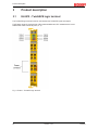
3.1 EL6910 - TwinSAFE logic terminal ............................................................................................... 10
3.2 Intended use ................................................................................................................................. 11
3.3 Technical data .............................................................................................................................. 12
3.4 Safety parameters ........................................................................................................................ 13
3.5 Dimensions ................................................................................................................................... 14
4 Operation..................................................................................................................................................15
4.1 Environmental conditions.............................................................................................................. 15
4.2 Installation..................................................................................................................................... 15
4.2.1 Safety instructions............................................................................................................15
4.2.2 Transport / storage...........................................................................................................15
4.2.3 Mechanical installation.....................................................................................................15
4.2.4 Electrical installation.........................................................................................................19
4.2.5 TwinSAFE reaction times.................................................................................................23
4.3 Operation in potentially explosive atmospheres (ATEX) .............................................................. 25
4.3.1 Special conditions ............................................................................................................25
4.3.2 Identification.....................................................................................................................25
4.3.3 Date code and serial number...........................................................................................25
4.3.4 Further ATEX documentation ..........................................................................................26
4.4 Configuration of the terminal in TwinCAT ..................................................................................... 26
4.4.1 Configuration requirements..............................................................................................26
4.4.2 Adding an EtherCAT coupler ..........................................................................................26
4.4.3 Adding an EtherCAT Terminal .........................................................................................26
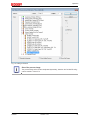
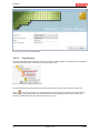
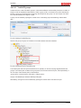
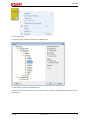
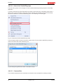
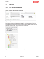
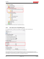
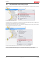
4.4.4 Adding an EL6910 ...........................................................................................................26
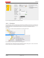
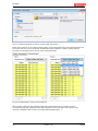
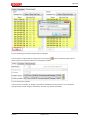
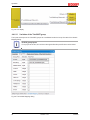
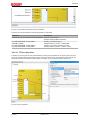
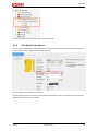
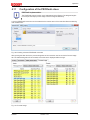
4.4.5 Address settings on TwinSAFE terminals with 1023 possible addresses........................28
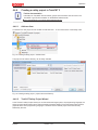
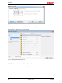
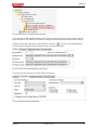
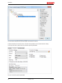
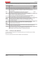
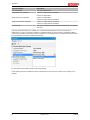
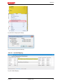
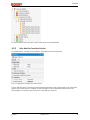
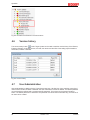
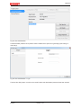
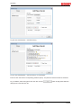
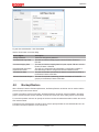
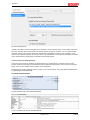
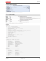
4.4.6 Creating a safety project in TwinCAT3 ...........................................................................29
4.4.7 Downloading the safety application .................................................................................56
4.4.8 Online Mode.....................................................................................................................59
4.5 Info Data ....................................................................................................................................... 64
4.5.1 Info data for the connection ............................................................................................64
4.5.2 Info data for function blocks .............................................................................................65
4.5.3 Info data for the TwinSAFE group....................................................................................66
4.5.4 Info data for the device ....................................................................................................67
4.6 Version history .............................................................................................................................. 68
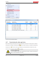
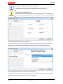
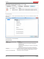
4.7 User Administration ...................................................................................................................... 68
4.8 Backup/Restore ............................................................................................................................ 71
4.9 Export/import of the safety project ................................................................................................ 74
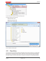
4.10 Diag history................................................................................................................................... 75

Table of contents
EL69104 Version: 1.4.1
4.11 Configuration of the PROFIsafe slave .......................................................................................... 77
4.11.1 Configuration of the slave connection in the PROFIsafe master software.......................79
4.11.2 Configuration of the PROFINET device ...........................................................................79
4.11.3 Sample program for parameterization .............................................................................80
4.12 Configuration of the PROFIsafe master........................................................................................ 82
4.12.1 Valid PROFIsafe configurations.......................................................................................84
4.12.2 Invalid PROFIsafe configurations ....................................................................................85
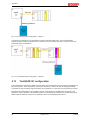
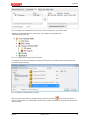
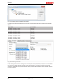
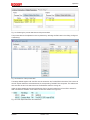
4.13 TwinSAFE SC configuration ......................................................................................................... 86
4.14 Customizing / disabling TwinSAFE groups................................................................................... 90
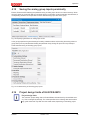
4.15 Saving the analog group inputs persistently ................................................................................. 93
4.16 Project design limits of EL6910/EJ6910 ....................................................................................... 93
4.17 Diagnostics ................................................................................................................................... 94
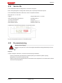
4.17.1 Diagnostic LEDs...............................................................................................................94
4.17.2 Status LEDs .....................................................................................................................96
4.17.3 Diagnostic objects............................................................................................................97
4.17.4 Cycle time of the safety project........................................................................................98
4.18 Maintenance ................................................................................................................................. 98
4.19 Service life .................................................................................................................................... 99
4.20 Decommissioning ......................................................................................................................... 99
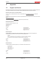
5 Appendix ................................................................................................................................................100
5.1 Support and Service ................................................................................................................... 100
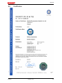
5.2 Certificates.................................................................................................................................. 101

Foreword
EL6910 5Version: 1.4.1
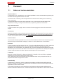
1 Foreword
1.1 Notes on the documentation
Intended audience
This description is only intended for the use of trained specialists in control and automation engineering who
are familiar with the applicable national standards.
It is essential that the following notes and explanations are followed when installing and commissioning
these components.
The responsible staff must ensure that the application or use of the products described satisfy all the
requirements for safety, including all the relevant laws, regulations, guidelines and standards.
Origin of the document
This documentation was originally written in German. All other languages are derived from the German
original.
Currentness
Please check whether you are using the current and valid version of this document. The current version can
be downloaded from the Beckhoff homepage at http://www.beckhoff.com/english/download/twinsafe.htm.
In case of doubt, please contact Technical Support [}100].
Product features
Only the product features specified in the current user documentation are valid. Further information given on
the product pages of the Beckhoff homepage, in emails or in other publications is not authoritative.
Disclaimer
The documentation has been prepared with care. The products described are subject to cyclical revision. For
that reason the documentation is not in every case checked for consistency with performance data,
standards or other characteristics. We reserve the right to revise and change the documentation at any time
and without prior announcement. No claims for the modification of products that have already been supplied
may be made on the basis of the data, diagrams and descriptions in this documentation.
Trademarks
Beckhoff
®
, TwinCAT
®
, EtherCAT
®
, Safety over EtherCAT
®
, TwinSAFE
®
, XFC
®
and XTS
®
are registered
trademarks of and licensed by Beckhoff Automation GmbH.
Other designations used in this publication may be trademarks whose use by third parties for their own
purposes could violate the rights of the owners.
Patent Pending
The EtherCAT Technology is covered, including but not limited to the following patent applications and
patents: EP1590927, EP1789857, DE102004044764, DE102007017835 with corresponding applications or
registrations in various other countries.
The TwinCAT Technology is covered, including but not limited to the following patent applications and
patents: EP0851348, US6167425 with corresponding applications or registrations in various other countries.

Foreword
EL69106 Version: 1.4.1
EtherCAT
®
is registered trademark and patented technology, licensed by Beckhoff Automation GmbH,
Germany
Copyright
© Beckhoff Automation GmbH & Co. KG, Germany.
The reproduction, distribution and utilization of this document as well as the communication of its contents to
others without express authorization are prohibited.
Offenders will be held liable for the payment of damages. All rights reserved in the event of the grant of a
patent, utility model or design.
Delivery conditions
In addition, the general delivery conditions of the company Beckhoff Automation GmbH & Co. KG apply.
1.2 Safety instructions
1.2.1 Delivery state
All the components are supplied in particular hardware and software configurations appropriate for the
application. Modifications to hardware or software configurations other than those described in the
documentation are not permitted, and nullify the liability of Beckhoff Automation GmbH & Co. KG.
1.2.2 Operator's obligation to exercise diligence
The operator must ensure that
• the TwinSAFE products are only used as intended (see chapter Product description);
• the TwinSAFE products are only operated in sound condition and in working order.
• the TwinSAFE products are operated only by suitably qualified and authorized personnel.
• the personnel is instructed regularly about relevant occupational safety and environmental protection
aspects, and is familiar with the operating instructions and in particular the safety instructions contained
herein.
• the operating instructions are in good condition and complete, and always available for reference at the
location where the TwinSAFE products are used.
• none of the safety and warning notes attached to the TwinSAFE products are removed, and all notes
remain legible.

Foreword
EL6910 7Version: 1.4.1
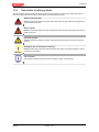
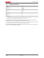
1.2.3 Description of safety symbols
In these operating instructions the following symbols are used with an accompanying safety instruction or
note. The safety instructions must be read carefully and followed without fail!
DANGER
Serious risk of injury!
Failure to follow the safety instructions associated with this symbol directly endangers the
life and health of persons.
WARNING
Risk of injury!
Failure to follow the safety instructions associated with this symbol endangers the life and
health of persons.
CAUTION
Personal injuries!
Failure to follow the safety instructions associated with this symbol can lead to injuries to
persons.
Attention
Damage to the environment or devices
Failure to follow the instructions associated with this symbol can lead to damage to the en-
vironment or equipment.
Note
Tip or pointer
This symbol indicates information that contributes to better understanding.

Foreword
EL69108 Version: 1.4.1
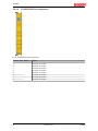
1.3 Documentation issue status
Version Comment
1.4.1 • Technical data permissible air pressure expanded
1.4.0 • Screenshots of User Administration updated
• State and Diag of TwinSAFE group updated
• EC Examination certificate added
1.3.0 • Screenshots updated
• Certificate added
1.2.0 • Reference to standards updated
• Safety parameters updated
1.1.0 • Description of diagnosis object 0xFEA0 extended
1.0.0 • First released version
• Backup / Restore description extended
0.5.0 • Description of external connections, properties of the FB ports, parameterizing of alias
devices, variable mapping and customizing updated
0.4.0 • Description of the group sequence added
• Check Safe Addresses description added
0.3.0 • System description added
0.2.0 • Screenshots for TwinCAT release adapted
• Description of info data revised
• LED description added
0.1.0 • Migration and structural adaptation
0.0.7 • System description updated
0.0.6 • Online display extended
0.0.5 • TwinSAFE group description extended
0.0.4 • PROFIsafe master/slave description extended
0.0.3 • Customizing extended
0.0.2 • Creating network and group descriptions
0.0.1 • Creation of the document

TwinSAFE System Description
EL6910 9Version: 1.4.1
2 TwinSAFE System Description
2.1 Extension of the Beckhoff I/O system with safety
functions
The TwinSAFE products from Beckhoff enable convenient expansion of the Beckhoff I/O system with safety
components, and integration of all the cabling for the safety circuit within the existing fieldbus cable. Safe
signals can be mixed with standard signals as required. The transfer of safety-related TwinSAFE telegrams
is handled by the standard controller. Maintenance is simplified significantly thanks to faster diagnosis and
simple replacement of components.
The following basic functionalities are included in the TwinSAFE components:
digital inputs (e.g. EL19xx, EP1908), digital outputs (e.g. EL29xx), drive components (e.g. AX5805) and logic
units (e.g. EL6900, EL6910). For a large number of applications, the complete safety sensor and actuator
technology can be wired on these components. The required logical link of the inputs and the outputs is
handled by the EL69xx. In addition to Boolean operations, the EL6910 now also enables analog operations.
2.2 Safety concept
TwinSAFE: Safety and I/O technology in one system
• Extension of the familiar Beckhoff I/O system with TwinSAFE components
• Safe and non-safe components can be combined as required
• Logical link of the I/Os in the EL69xx TwinSAFE logic terminal
• Suitable for applications up to SIL3 according to EN61508:2010 and Cat4, PLe according to
DINENISO13849-1:2016-06
• Safety-relevant networking of machines via bus systems
• In the event of an error, all TwinSAFE components always switch to the wattless and therefore safe
state
• No safety requirements for the higher-level standard TwinCAT system
Safety over EtherCAT protocol (FSoE)
• Transfer of safety-relevant data via any media (“genuine black channel”)
• TwinSAFE communication via fieldbus systems such as EtherCAT, Lightbus, PROFIBUS, PROFINET
or Ethernet
• IEC 61508:2010 SIL 3 compliant
• FSoE is IEC standard (IEC 61784-3-12) and ETG standard (ETG.5100)
Fail-safe principle (fail stop)
The basic rule for a safety system such as TwinSAFE is that failure of a part, a system component or the
overall system must never lead to a dangerous condition. The safe state is always the switched off and
wattless state.
CAUTION
Safe state
For all TwinSAFE components the safe state is always the switched-off, wattless state.

Product description
EL691010 Version: 1.4.1
3 Product description
3.1 EL6910 - TwinSAFE logic terminal
The TwinSAFE logic terminal is the link unit between the TwinSAFE inputs and outputs.
The EL6910 meets the requirements of IEC62061:2005/A2:2015, IEC61508:2010SIL3 and
DINENISO13849-1:2016-06 (Cat4,PLe).
Fig.1: EL6910 - TwinSAFE logic terminal

Product description
EL6910 11Version: 1.4.1
3.2 Intended use
WARNING
Caution - Risk of injury!
TwinSAFE components may only be used for the purposes described below!
The TwinSAFE terminals expand the application range of Beckhoff Bus Terminal system with functions that
enable them to be used for machine safety applications. The TwinSAFE terminals are designed for machine
safety functions and directly associated industrial automation tasks. They are therefore only approved for
applications with a defined fail-safe state. This safe state is the wattless state. Fail-safety according to the
relevant standards is required.
The EL6910 TwinSAFE logic terminal is suitable for operation at the
• Beckhoff EKxxxx series Bus Couplers
• Beckhoff CXxxxx series Embedded PCs with E-bus connection
WARNING
System limits
The TÜV SÜD certificate applies to the EL6910, the function blocks available in it, the doc-
umentation and the engineering tool. Approved engineering tools are TwinCAT 3.1, Twin-
SAFE Loader and CODESYS Safety for EtherCAT Safety Module. Any deviations from the
procedures or tools, particularly externally generated xml files for TwinSAFE import or ex-
ternally generated automatic project creation procedures, are not covered by the certificate.
WARNING
Power supply from SELV/PELV power supply unit!
The TwinSAFE components must be supplied with 24V
DC
by an SELV/PELV power supply
unit with an output voltage limit U
max
of 36V
DC
. Failure to observe this can result in a loss of
safety.
CAUTION
Follow the machinery directive!
The TwinSAFE components may only be used in machines as defined in the machinery di-
rective.
CAUTION
Ensure traceability!
The buyer has to ensure the traceability of the device via the serial number.

Product description
EL691012 Version: 1.4.1
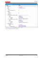
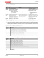
3.3 Technical data
Product designation EL6910
Number of inputs 0
Number of outputs 0
Status display 4 diagnostic LEDs
Minimum/maximum cycle time approx. 1 ms / according the project size
Error reaction time ≤ watchdog times
Watchdog time min. 2 ms, max. 60000 ms
Input process image Dynamic, according to the TwinSAFE configuration in TwinCAT3
Output process image Dynamic, according to the TwinSAFE configuration in TwinCAT3
Supply voltage (SELV/PELV) 24V
DC
(–15%/+20%)
Current consumption via E-bus approx. 160 mA
Power dissipation of the terminal typically 1 W
Dimensions (W x H x D) 12mm x 100mm x 68mm
Weight approx. 50 g
Permissible ambient temperature (operation)
-25°C to +55°C (see notes in section Sample configuration for
temperature measurement [}17])
Permissible ambient temperature (transport/storage) -40°C to +70°C
Permissible air humidity 5% to 95%, non-condensing
Permissible air pressure (operation/storage/transport) 750hPa to 1100hPa
(this corresponds to a height of approx. -690m to 2450m over sea
level assuming an international standard atmosphere)
Climate category according to EN 60721-3-3 3K3
(the deviation from 3K3 is possible only with optimal environmental
conditions and also applies only to the technical data which are
specified differently in this documentation)
Permissible level of contamination according to EN60664-1
level of contamination 2 (comply with the chapter Maintenance
[}98])
Impermissible operating conditions TwinSAFE terminals must not be used under the following operat-
ing conditions:
• under the influence of ionizing radiation (that exceeds the
level of the natural environmental radiation)
• in corrosive environments
• in an environment that leads to unacceptable soiling of the
Bus Terminal
Vibration/shock resistance conforms to EN 60068-2-6 / EN 60068-2-27
EMC immunity/emission conforms to EN 61000-6-2 / EN 61000-6-4
Shocks 15 g with pulse duration 11 ms in all three axes
Protection class IP20
Permitted operating environment In the control cabinet or terminal box, with minimum protection
class IP54 according to IEC60529
Permissible installation position
see chapter Installation position and minimum distances [}16]
Approvals CE, cULus, ATEX in preparation, TÜVSÜD

Product description
EL6910 13Version: 1.4.1
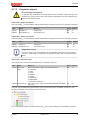
3.4 Safety parameters
Key figures EL6910
Lifetime [a] 20
Prooftest Interval [a] not required 1)
PFH
D
1.79E-09
%SIL3 of PFH
D
1,79%
PFD
avg
2.54E-05
%SIL3 of PFD
avg
2,54%
MTTF
d
high
DC high
Performance Level PL e
Category 4
HFT 1
Element classification* Type B
1. Special proof tests are not required during the entire service life of the EL6910 EtherCAT terminal.
2. Classification according to IEC 61508-2:2010 (see chapters 7.4.4.1.2 and 7.4.4.1.3)
The EL6910 EtherCAT Terminal can be used for safety-related applications according to IEC62061 and
IEC61508:2010 up to SIL3 and DINENISO13849-1:2016-06 up to PLe(Cat4).
For the calculation or estimation of the MTTF
d
value from the PFH
D
value, further information can be found in
the TwinSAFE application manual or in DIN EN ISO 13849-1:2016-06 Table K.1.
In terms of safety-related parameters, the Safety over EtherCAT communication is already considered with
1% of SIL3 according to the protocol specification.

Product description
EL691014 Version: 1.4.1
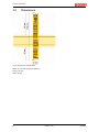
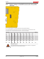
3.5 Dimensions
Fig.2: Dimensions of the EL6910
Width: 12 mm (side-by-side installation)
Height: 100 mm
Depth: 68 mm

Operation
EL6910 15Version: 1.4.1
4 Operation
4.1 Environmental conditions
Please ensure that the TwinSAFE components are only transported, stored and operated under the specified
conditions (see technical data)!
WARNING
Risk of injury!
The TwinSAFE components must not be used under the following operating conditions.
• under the influence of ionizing radiation (that exceeds the level of the natural environ-
mental radiation)
• in corrosive environments
• in an environment that leads to unacceptable soiling of the TwinSAFE component
Attention
Electromagnetic compatibility
The TwinSAFE components comply with the current standards on electromagnetic compat-
ibility with regard to spurious radiation and immunity to interference in particular.
However, in cases where devices such as mobile phones, radio equipment, transmitters or
high-frequency systems that exceed the interference emissions limits specified in the stan-
dards are operated near TwinSAFE components, the function of the TwinSAFE compo-
nents may be impaired.
4.2 Installation
4.2.1 Safety instructions
Before installing and commissioning the TwinSAFE components please read the safety instructions in the
foreword of this documentation.
4.2.2 Transport / storage
Use the original packaging in which the components were delivered for transporting and storing the
TwinSAFE components.
CAUTION
Note the specified environmental conditions
Please ensure that the digital TwinSAFE components are only transported and stored un-
der the specified environmental conditions (see technical data).
4.2.3 Mechanical installation
DANGER
Risk of injury!
Bring the bus system into a safe, de-energized state before starting installation, disassem-
bly or wiring of the devices!
4.2.3.1 Control cabinet / terminal box
The TwinSAFE terminals must be installed in a control cabinet or terminal box with IP54 protection class
according to IEC60529 as a minimum.

Operation
EL691016 Version: 1.4.1
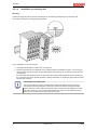
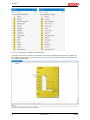
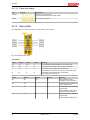
4.2.3.2 Installation position and minimum distances
For the prescribed installation position the mounting rail is installed horizontally and the mating surfaces of
the EL/KL terminals point toward the front (see illustration below). The terminals are ventilated from below,
which enables optimum cooling of the electronics through convection. The direction indication “down”
corresponds to the direction of positive acceleration due to gravity.
Fig.3: Installation position and minimum distances
In order to ensure optimum convection cooling, the distances to neighboring devices and to control cabinet
walls must not be smaller than those shown in the diagram.

Operation
EL6910 17Version: 1.4.1
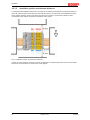
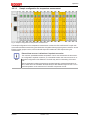
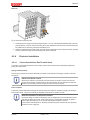
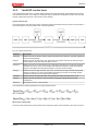
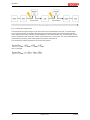
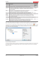
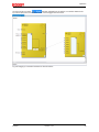
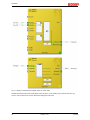
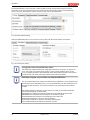
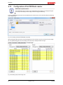
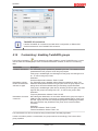
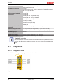
4.2.3.3 Sample configuration for temperature measurement
Fig.4: Sample configuration for temperature measurement
The sample configuration for the temperature measurement consists of an EK1100 EtherCAT coupler with
connected terminals that match the typical distribution of digital and analog signal types at a machine. On the
EL6910 a safety project is active, which reads safe inputs and enables all 4 safe outputs during the
measurement.
Note
External heat sources / radiant heat / impaired convection
The maximum permissible ambient temperature of 55°C was checked with the above sam-
ple configuration. Impaired convection, an unfavorable location near heat sources or an un-
favorable configuration of the EtherCAT Terminals may result in overheating of the termi-
nals.
The key parameter is always the maximum permitted internally measured temperature of
95°C, above which the TwinSAFE terminals switch to safe state and report an error. The in-
ternal temperature can be read from the TwinSAFE components via CoE.

Operation
EL691018 Version: 1.4.1
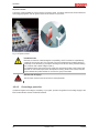
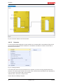
4.2.3.4 Installation on mounting rails
Mounting
The Bus Couplers and Bus Terminals are attached to commercially available 35mm mounting rails
(according to EN60715) by applying slight pressure:
Fig.5: Installation on the mounting rail
1. First attach the Fieldbus Coupler to the mounting rail.
2. The Bus Terminals are now attached on the right-hand side of the fieldbus Coupler. Join the compo-
nents with slot and key and push the terminals against the mounting rail, until the lock clicks onto the
mounting rail.
If the terminals are clipped onto the mounting rail first and then pushed together without slot and key,
the connection will not be operational! When correctly assembled, no significant gap should be visible
between the housings.
Note
Fastening of mounting rails
The locking mechanism of the terminals and couplers protrudes into the profile of the
mounting rail. When installing the components, make sure that the locking mechanism
doesn't come into conflict with the fixing bolts of the mounting rail. For fastening mounting
rails with a height of 7.5 mm under the terminals and couplers, use flat fastening compo-
nents such as countersunk head screws or blind rivets.

Operation
EL6910 19Version: 1.4.1
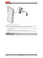
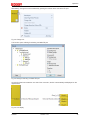
Removal
Fig.6: Removal of mounting rails
1. Carefully pull the orange-colored lugs approximately 1 cm out of the disassembled terminal, until they
protrude loosely. The lock with the mounting rail is now released for this terminal, and the terminal can
be pulled from the mounting rail without excessive force.
2. Grasp the released terminal with thumb and index finger simultaneous at the upper and lower grooved
housing surfaces and pull the terminal away from the mounting rail.
4.2.4 Electrical installation
4.2.4.1 Connections within a Bus Terminal block
The electric connections between the Bus Coupler and the Bus Terminals are automatically realized by
joining the components:
Spring contacts (E-bus)
The six spring contacts of the E-bus deal with the transfer of the data and the supply of the Bus Terminal
electronics.
Note
Observe the E-bus current
Observe the maximum current that your Bus Coupler can supply to the E-bus! Use the
EL9410 Power Supply Terminal if the current consumption of your terminals exceeds the
maximum current that your Bus Coupler can feed to the E-bus supply.
Power contacts
The power contacts deal with the supply for the field electronics and thus represent a supply rail within the
Bus Terminal block. The power contacts are supplied via terminals on the Bus Coupler.
Note
Note the connection of the power contacts
During the design of a Bus Terminal block, the pin assignment of the individual Bus Termi-
nals must be taken account of, since some types (e.g. analog Bus Terminals or digital 4-
channel Bus Terminals) do not or not fully loop through the power contacts.
Power Feed Terminals (EL91xx, EL92xx) interrupt the power contacts and thus represent
the start of a new supply rail.

Operation
EL691020 Version: 1.4.1
PE power contact
The power contact labelled PE can be used as a protective earth. For safety reasons this contact mates first
when plugging together, and can ground short-circuit currents of up to 125A.
Fig.7: PE power contact
CAUTION
Insulation tests
Note that, for reasons of electromagnetic compatibility, the PE contacts are capacitatively
coupled to the mounting rail. This may lead to incorrect results during insulation testing or
to damage on the terminal (e.g. disruptive discharge to the PE line during insulation testing
of a consumer with a rated voltage of 230 V).
For insulation testing, disconnect the PE supply line at the Bus Coupler or the Power Feed
Terminal! In order to decouple further feed points for testing, these Power Feed Terminals
can be released and pulled at least 10 mm from the group of terminals.
DANGER
Serious risk of injury!
The PE power contact must not be used for other potentials!
4.2.4.2 Overvoltage protection
If protection against overvoltage is necessary in your plant, provide a surge filter for the voltage supply to the
Bus Terminal blocks and the TwinSAFE terminals.
Page is loading ...
Page is loading ...
Page is loading ...
Page is loading ...
Page is loading ...
Page is loading ...
Page is loading ...
Page is loading ...
Page is loading ...
Page is loading ...
Page is loading ...
Page is loading ...
Page is loading ...
Page is loading ...
Page is loading ...
Page is loading ...
Page is loading ...
Page is loading ...
Page is loading ...
Page is loading ...
Page is loading ...
Page is loading ...
Page is loading ...
Page is loading ...
Page is loading ...
Page is loading ...
Page is loading ...
Page is loading ...
Page is loading ...
Page is loading ...
Page is loading ...
Page is loading ...
Page is loading ...
Page is loading ...
Page is loading ...
Page is loading ...
Page is loading ...
Page is loading ...
Page is loading ...
Page is loading ...
Page is loading ...
Page is loading ...
Page is loading ...
Page is loading ...
Page is loading ...
Page is loading ...
Page is loading ...
Page is loading ...
Page is loading ...
Page is loading ...
Page is loading ...
Page is loading ...
Page is loading ...
Page is loading ...
Page is loading ...
Page is loading ...
Page is loading ...
Page is loading ...
Page is loading ...
Page is loading ...
Page is loading ...
Page is loading ...
Page is loading ...
Page is loading ...
Page is loading ...
Page is loading ...
Page is loading ...
Page is loading ...
Page is loading ...
Page is loading ...
Page is loading ...
Page is loading ...
Page is loading ...
Page is loading ...
Page is loading ...
Page is loading ...
Page is loading ...
Page is loading ...
Page is loading ...
Page is loading ...
Page is loading ...
Page is loading ...
Page is loading ...
Page is loading ...
Page is loading ...
-
 1
1
-
 2
2
-
 3
3
-
 4
4
-
 5
5
-
 6
6
-
 7
7
-
 8
8
-
 9
9
-
 10
10
-
 11
11
-
 12
12
-
 13
13
-
 14
14
-
 15
15
-
 16
16
-
 17
17
-
 18
18
-
 19
19
-
 20
20
-
 21
21
-
 22
22
-
 23
23
-
 24
24
-
 25
25
-
 26
26
-
 27
27
-
 28
28
-
 29
29
-
 30
30
-
 31
31
-
 32
32
-
 33
33
-
 34
34
-
 35
35
-
 36
36
-
 37
37
-
 38
38
-
 39
39
-
 40
40
-
 41
41
-
 42
42
-
 43
43
-
 44
44
-
 45
45
-
 46
46
-
 47
47
-
 48
48
-
 49
49
-
 50
50
-
 51
51
-
 52
52
-
 53
53
-
 54
54
-
 55
55
-
 56
56
-
 57
57
-
 58
58
-
 59
59
-
 60
60
-
 61
61
-
 62
62
-
 63
63
-
 64
64
-
 65
65
-
 66
66
-
 67
67
-
 68
68
-
 69
69
-
 70
70
-
 71
71
-
 72
72
-
 73
73
-
 74
74
-
 75
75
-
 76
76
-
 77
77
-
 78
78
-
 79
79
-
 80
80
-
 81
81
-
 82
82
-
 83
83
-
 84
84
-
 85
85
-
 86
86
-
 87
87
-
 88
88
-
 89
89
-
 90
90
-
 91
91
-
 92
92
-
 93
93
-
 94
94
-
 95
95
-
 96
96
-
 97
97
-
 98
98
-
 99
99
-
 100
100
-
 101
101
-
 102
102
-
 103
103
-
 104
104
-
 105
105


Beckhoff TwinSAFE EL6910 Operating instructions
- Type
- Operating instructions
Ask a question and I''ll find the answer in the document
Finding information in a document is now easier with AI
Related papers
-
 Beckhoff TwinSAFE EL6910 Operating instructions
-
 Beckhoff EJ6910 Operating instructions
-
 Beckhoff EK1960 Series Operating Instructions Manual
-
 Beckhoff EL1918 Operating Instructions Manual
-
 Beckhoff EL2911 Operating Instructions Manual
-
 Beckhoff TwinSAFE EL2912 Operating Instructions Manual
-
 Beckhoff EL6900 Operating Instructions Manual
-
 Beckhoff EP1918 Operating
-
 Beckhoff AX8-1 Series Documentation
-
 Beckhoff TwinSAFE EJ1918 Operating instructions


Other documents
-
JUMO LOGOSCREEN 700 User manual
-
Keba FSM Modul, FSoE Master Installation guide
-
Kollmorgen AKT-PRB-000-000 Installation guide
-
WAGO 8FDI 24V DC PROFIsafe V1.3 User manual
-
JUNG TKTI02REG Operating instructions
-
-
LG AX5000 alltel User manual
-
Pepperl+Fuchs VBG-PN-K20-D-EV24 Owner's manual
-
 Korber Solutions LTI MOTION MotionOne 3 System Manual
-
Phoenix Contact Axioline F User manual
