Page is loading ...

IB-1 • 1
INTERFACE BOARD
KIT
Ramsey Electronics Model No. IB1
• Quick connection to a TV or VCR
• Runs from a 12 to 15 volt power supply
• Great for watching the kids outside while you’re busy inside
• Includes a microphone allowing audio as well as video
outputs
• The ultimate baby monitor!
• Educational and fun to build!
• Informative manual leads you through step by step to ensure
an operating unit when complete.
• Interface board allows for use in dark places including at
night.
Ever want to spy on a friend or an enemy without them knowing
it? Well now you can with the IB-1. It is small enough that it can
easily be hidden, yet it picks up audio as well as video! The
Interface board picks up infra-red light, allowing it to be used at
night or in dark places.
I can see and
hear you

IB-1 • 2
RAMSEY TRANSMITTER KITS
• FM10A, FM25B FM Stereo Transmitters
• TV6, Television Transmitter
• MR6, Model Rocket Tracking Transmitter
RAMSEY RECEIVER KITS
• FR1 FM Broadcast Receiver
• AR1 Aircraft Band Receiver
• SR2 Shortwave Receiver
• AA7 Active Antenna
• SC1 Shortwave Converter
RAMSEY HOBBY KITS
• SG7 Personal Speed Radar
• SS70A Speech Scrambler
• TT1 Telephone Recorder
• SP1 Speakerphone
• MD3 Microwave Motion Detector
• PH10 Peak hold Meter
• LC1 Inductance-Capacitance Meter
RAMSEY AMATEUR RADIO KITS
• DDF1 Doppler Direction Finder
• HR Series HF All Mode Receivers
• QRP Series HF CW Transmitters
• CPO3 Code Practice Oscillator
• QRP Power Amplifiers
RAMSEY MINI-KITS
Many other kits are available for hobby, school, Scouts and just plain FUN. New
kits are always under development. Write or call for our free Ramsey catalog.
IB1 INTERFACE BOARD KIT
Ramsey Electronics publication NO. MIB1 Rev. 1.5a
First printing: December 1994
COPYRIGHT 1994 by Ramsey Electronics, Inc. 590 Fishers Station Drive, Victor, New York
14564. All rights reserved. No portion of this publication may be copied or duplicated without the
written permission of Ramsey Electronics, Inc. Printed in the United States of America.

IB-1 • 3
INTERFACE BOARD
KIT
Ramsey Publication No. MIB1
Price $5.00
TABLE OF CONTENTS
Introduction to the IB1 ................... 4
How It Works ................................. 4
Kit Building Tips ............................. 4
Parts list ......................................... 5
IB1 Placement Diagram ................ 6
IB1 Schematic Diagram ................. 6
IB1 Assembly Instructions ............. 8
Set-Up ............................................ 9
Troubleshooting ............................. 9
Concealment Ideas ........................ 10
Ramsey Warranty .......................... 11
KIT ASSEMBLY
AND INSTRUCTION MANUAL FOR
RAMSEY ELECTRONICS, INC.
590 Fishers Station Drive
Victor, New York 14564
Phone (585) 924-4560
Fax (585) 924-4555
www.ramseykits.com

IB-1 • 4
Introduction:
It is now possible to monitor what is happening at night as well as during the
daylight hours with the Interface board kit and a camera. By virtue of infrared
LEDs for night vision and a microphone attached to an amplifier circuit, you
can use it to spy on someone or as a means of added security. The Interface
board connects directly to your choice of small video cameras and has a
video and an audio output which can be plugged into a VCR or a TV (if your
TV has audio and video jacks on it ).
How It Works:
The circuit is powered by a 12 to 15 volt supply, used to operate the camera
as well as the rest of the circuit including the optional infra-red LEDs. U1 and
D1 regulate the DC supply voltage to 9 or 12 V for use in the circuit. Video is
fed directly from your camera module to the video output jack, J2.
Microphone audio is amplified by Q1 and Q2 and fed to audio output jack J3.
Test points E and F allow for connection to infra-red LEDs if so desired.
Optional R10 and R11 are current limiting resistors.
An interesting note: Because it uses state-of-the-art CCD (charge coupled
device) technology, the IB1 is extremely sensitive at low light levels, even at
infrared wavelengths. It’s possible to view the IR coming from your TV
remote control with the IB1. Also, the IB1 can be placed behind a piece of
dark Plexiglas, blocking visible light while allowing infra-red through...what an
idea for covert surveillance!
Kit building tips:
Use a good soldering technique - let your soldering iron tip gently heat the
traces to which you are soldering, heating both wires and pads
simultaneously. Apply the solder to the iron and the pad when the pad is hot
enough to melt the solder. The finished joint should look like a drop of water
on paper, somewhat soaked in.
Mount all electrical parts on the top side of the board provided. This is the
side that has no traces or pads on it.
Electrical part installation - when parts are installed, the part is placed flat to
the board, and the leads are bent on the backside of the board to prevent the
part from falling out before soldering. The part is then soldered securely to
the board; the remaining lead length is clipped off.

IB-1 • 5
IB1 Parts List:
I
t is a good idea to check off the components in the boxes provided and to
separate them as you go along. This will save hunting for specific components
later.
RESISTORS
❒ 2 470 ohm resistors [yellow-violet -brown] (R8, R9)
❒ 2 1K ohm resistors [brown-black-red] (R1,R4)
❒ 3 10K ohm resistors [brown-black-orange] (R2, R3, R7)
❒ 2 22K ohms resistors [red-red-orange] (R5, R6)
CAPACITORS
❒ 1 .1uF capacitor (C4)
❒ 5 10uF electrolytic capacitors (C1, C2, C3, C5, C6)
SEMICONDUCTORS
❒ 2 2N3904 NPN transistors (Q1, Q2)
❒ 1 7808, 8 volt regulator (U1)(see text)
❒ 1 7812, 12 volt regulator (U1)(see text)
❒ 2 1N4002 diodes (D1,D2)
MISCELLANEOUS PARTS AND HARDWARE
❒ 1 power jack (J1)
❒ 2 RCA jacks (J2, J3)
❒ 1 MC-1A microphone (MK-1)
OPTIONAL
(not provided)
❒ 2 resistors (see chart on page 8)
❒ 1-6 infrared LEDs

IB-1 • 6

IB-1 • 7
CONSTRUCTION OF THE IB1 INTERFACE BOARD KIT
❒ 1. Install J2 and J3, the RCA style audio and video jacks, on the PC board.
These require some heat for the solder to flow so take your time.
❒ 2. Install J1, the power jack.
❒ 3. Install MK1, the microphone. If you are looking at the bottom of the
microphone the two pins should be on the top and side by side. The pin on
the left is positive and goes to the inside of the board.The pin on the right is
negative and goes to the outside of the board.
❒ 4. Install C1, C2, C3, C5, and C6; they are all 10 uF electrolytic capacitors.
Electrolytic capacitors are polarized with a (+) and a (-) lead and must be
installed in the correct orientation. Ordinarily only the negative side is
marked on the capacitor body with a dark band and a (-) sign clearly
shown. The PC board will usually show the (+) hole location. Use care to
ensure proper polarity, these components can burn out if installed
incorrectly.
❒ 5. Install R1 and R4, 1K ohm resistors (brown-black-red).
❒ 6. Install R2, R3, and R7, 10K ohm resistors (brown-black-orange). By
installing C3, R4, and R7 you have built an AC noise filter as well as a DC
power supply to the microphone.
❒ 7. Check the paperwork that came with your camera. If you have a 12 volt
camera, install the 12 volt regulator in the U1 position. If your camera runs
on 9 volts, install the 8 volt regulator. When looking at the flat side the
input pin is on the left, ground is the center pin, and the output is the right
pin. The flat side or the back of the regulator faces the outside of the board.
❒ 8. Install D1, the diode marked 1N4002. Follow the parts layout diagram
when installing it; the end with the white line on it is the negative end. If you
installed the 8 volt regulator in step 7, install D2, marked 1N4002. If you
installed the 12 volt regulator, install a small jumper wire in the D2 position.
The voltage regulator along with D1, D2, R1, C1, and C2 supply 9 or 12
volts to the camera.
❒ 9. Install Q1 and Q2, 2N3904 NPN transistors. When installing Q1 and Q2
observe the correct placement of the flat side. Press the transistor snugly
into the board so that only a minimum of wire is exposed above the board.
❒ 10. Install C4, .1 uF capacitor (marked .1 or 104).
❒ 11. Install R8 and R9, they are 470 ohm resistors (yellow-violet-brown).
❒ 12. Install R5 and R6, they are 22 K ohm resistor (red-red-orange). These
resistors along with R2, R3, R8, R9, C6, Q1, and Q2 are the audio
amplifier, the heart of the audio section.

IB-1 • 8
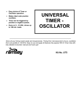
# of LEDs
R10 R11
1
470 ohms _
2
470 ohms 470 ohms
3
330 ohms 470 ohms
4
330 ohms 330 ohms
5
220 ohms 330 ohms
6
220 ohms 220 ohms
❒ 1. Install appropriate resistors R10 and R11.
❒ 2. Install infrared LEDs. Be sure that you connect them with the correct
orientation. The long lead is the anode (positive) and the short lead is the
cathode(negative). The anode is connected to either hole F or E on the PC
and the cathode is connected to hole G. You may want to use a wire to
connect the LED(s) to the PC so that they can be moved while the Interface
board itself does not.
CONGRATULATIONS
Now that you have completed your IB1 you may want to check to make sure
there are no solder bridges and that everything is in correctly. If something is
not right, be sure and make the correction before energizing the circuit.
❒ 13. Connect your camera. Follow the wiring diagram on the paperwork
enclosed with your camera.
OPTIONAL
If you are planning on using the Interface board at night or in dark areas you will
want to install R10 and R11 along with infrared LEDs. The brightness desired
can be changed by using more or less IR LEDs. The circuit is capable of
supporting up to 6 LEDs. With each LED change, R10 and R11 will also
change. Each LED connected to R10 (hole E) must be in series and each LED
connected to R11 (hole F) must also be connected in series.

IB-1 • 9
SET-UP:
The IB1 is designed to be powered by an external power supply using jack J1.
A 12 to 15 volt regulated DC supply is recommended, with the “center” pin of
the connector being the positive or the (+) connection.
1. Connect a suitable power supply to the IB1 board.
2. Connect the video output of the IB1 to the video input of your TV or
VCR.
3. Connect the audio output of the IB1 to the audio input of your TV or
VCR.
4. Adjust your TV to its auxiliary channel if you’re not using a VCR, if
you are using a VCR adjust your TV to either channel three or four;
whichever the VCR is set to. You may have to adjust the
tracking on your VCR.
5. If you have a clear picture along with good audio you can breath
a sigh of relief. If you don’t then look at the next section, trouble-
shooting.
TROUBLESHOOTING:
1. Check for cold solder joints. They'll look gray and dull as opposed to silver
and shiny.
2. NO VIDEO.
Make sure that the RCA connections are correct and check the TV/VCR
adjustments, channel and/or input settings.
3. NO VIDEO.
See if the correct voltage is being supplied to the camera at the camera
connection hole marked C. If not, make sure that you have power to the PC
board.
4. NO AUDIO.
If you don’t have voltage to the camera, as mentioned earlier, you also
don’t have any voltage going to the audio section of circuitry.
5. VERY LITTLE AUDIO
Check to make sure that Q1 and Q2 are installed properly and also the
resistors that are directly connected to them are the correct value.
If none of the above has helped you, then see the Ramsey kit warranty in the
manual.

IB-1 • 10
CONCEALMENT IDEAS:
There are many places that the Interface board and a small CCD camera
(check the Ramsey catalog or website at www.ramseykits.com) can be hidden
because of their size and maneuverability. The best place for you depends on
your application and what type of setting it is to be used in. The Interface board
and a camera could be used to watch the children, for security outside as well
as inside, or to capture the 10 thousand dollar home video. Here are a few
ideas that we came up with:
1. Looking out from behind a picture hanging on the wall.
2. In a ceiling tile
3. Behind the front grill of a speaker
4. Behind a mirror
5. In a register
6. Hanging up in back of the eaves
7. The inside of a garage door
8. In a bush
9. On a window sill behind a curtain
10. In a flower pot
11. In a cabinet with a glass door
12. Inside of a child's doll or toy
We have experimented and installed the Interface board and a camera
temporarily in a couple of offices. They were hidden in plants and air vents. The
wires were run into an adjacent office where the uninformed victims were
shown on television. It was great watching people get mad at their computers,
printers, and other instruments. There were a few choice words that people
came up with while they were a little upset. All in all, it was a blast watching
people do things that they wouldn’t normally do with others around.

IB-1 • 11
The Ramsey Kit Warranty
Please read carefully BEFORE calling or writing in about your kit. Most problems can be
solved without contacting the factory.
Notice that this is not a "fine print" warranty. We want you to understand your rights and ours too! All Ramsey
kits will work if assembled properly. The very fact that your kit includes this new manual is your assurance that
a team of knowledgeable people have field-tested several "copies" of this kit straight from the Ramsey
Inventory. If you need help, please read through your manual carefully, all information required to properly
build and test your kit is contained within the pages!
1. DEFECTIVE PARTS: It's always easy to blame a part for a problem in your kit, Before you conclude that a
part may be bad, thoroughly check your work. Today's semiconductors and passive components have
reached incredibly high reliability levels, and it’s sad to say that our human construction skills have not! But on
rare occasions a sour component can slip through. All our kit parts carry the Ramsey Electronics Warranty
that they are free from defects for a full ninety (90) days from the date of purchase. Defective parts will be
replaced promptly at our expense. If you suspect any part to be defective, please mail it to our factory for
testing and replacement. Please send only the defective part(s), not the entire kit. The part(s) MUST be
returned to us in suitable condition for testing. Please be aware that testing can usually determine if the part
was truly defective or damaged by assembly or usage. Don't be afraid of telling us that you 'blew-it', we're all
human and in most cases, replacement parts are very reasonably priced.
2. MISSING PARTS: Before assuming a part value is incorrect, check the parts listing carefully to see if it is a
critical value such as a specific coil or IC, or whether a RANGE of values is suitable (such as "100 to 500 uF").
Often times, common sense will solve a mysterious missing part problem. If you're missing five 10K ohm
resistors and received five extra 1K resistors, you can pretty much be assured that the '1K ohm' resistors are
actually the 'missing' 10 K parts ("Hum-m-m, I guess the 'red' band really does look orange!") Ramsey
Electronics project kits are packed with pride in the USA. If you believe we packed an incorrect part or omitted
a part clearly indicated in your assembly manual as supplied with the basic kit by Ramsey, please write or call
us with information on the part you need and proof of kit purchase
3. FACTORY REPAIR OF ASSEMBLED KITS:
To qualify for Ramsey Electronics factory repair, kits MUST:
1. NOT be assembled with acid core solder or flux.
2. NOT be modified in any manner.
3. BE returned in fully-assembled form, not partially assembled.
4. BE accompanied by the proper repair fee. No repair will be undertaken until we have received the
MINIMUM repair fee (1/2 hour labor) of $18.00, or authorization to charge it to your credit card
account.
5. INCLUDE a description of the problem and legible return address. DO NOT send a separate letter; include
all correspondence with the unit. Please do not include your own hardware such as non-Ramsey
cabinets, knobs, cables, external battery packs and the like. Ramsey Electronics, Inc., reserves the
right to refuse repair on ANY item in which we find excessive problems or damage due to
construction methods. To assist customers in such situations, Ramsey Electronics, Inc., reserves
the right to solve their needs on a case-by-case basis.
The repair is $36.00 per hour, regardless of the cost of the kit. Please understand that our technicians are not
volunteers and that set-up, testing, diagnosis, repair and repackaging and paperwork can take nearly an hour
of paid employee time on even a simple kit. Of course, if we find that a part was defective in manufacture,
there will be no charge to repair your kit (But please realize that our technicians know the difference between
a defective part and parts burned out or damaged through improper use or assembly).
4. REFUNDS: You are given ten (10) days to examine our products. If you are not satisfied, you may return
your unassembled kit with all the parts and instructions and proof of purchase to the factory for a full refund.
The return package should be packed securely. Insurance is recommended. Please do not cause needless
delays, read all information carefully.

IB-1 • 12
Interface board Kit
Quick Reference Page Guide
Introduction to the IB1 ...................... 4
How It Works .................................... 4
Kit Building Tips ............................... 4
Parts list ........................................... 5
IB1 Placement Diagram ................... 6
IB1 Schematic Diagram ................... 6
IB1 Assembly Instructions ................ 8
Set-Up .............................................. 9
Troubleshooting ............................... 9
Hidden Ideas .................................... 10
Ramsey Warranty ............................ 11
Price: $5.00
Ramsey Publication No. IB1
Assembly and Instruction manual for:
RAMSEY MODEL NO. IB1 INTERFACE BOARD KIT
RAMSEY ELECTRONICS, INC.
590 Fishers Station Drive
Victor, New York 14564
Phone (585) 924-4560
Fax (585) 924-4555
REQUIRED TOOLS
• Soldering Iron Ramsey WLC100
• Thin Rosin Core Solder Ramsey RTS12
• Needle Nose Pliers Ramsey MPP4 or
RTS05
• Small Diagonal Cutters Ramsey RTS04
<OR> Technician’s Tool Kit TK405
ADDITIONAL SUGGESTED ITEMS
• Holder for PC Board/Parts Ramsey HH3
• Desoldering Braid Ramsey RTS08
• Digital Multimeter Ramsey M133
TOTAL SOLDER POINTS
70
ESTIMATED ASSEMBLY
TIME
Beginner ............... 2.1 hrs
Intermediate ......... 1.2 hrs
Advanced .............0.9 hrs
/