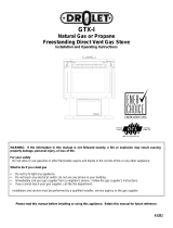
Vermont Casting Gas Heater SDDVTCB, SDDVTEB, SDDVTMB, SDDVTBS, SDDVTCH, SDDVTVG, SDDVTBD,SDDVTCCB, SDDVTCEB, SDDVTCMB, SDDVTCBS, SDDVTCCH, SDDVTCVG, SDDVTCBD User manual
- Category
- Stoves
- Type
- User manual

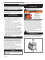
INSTALLER / CONSUMER
SAFETY INFORMATION
PLEASE READ THIS MANUAL
BEFORE INSTALLING AND USING
APPLIANCE.
WARNING!
IF THE INFORMATION IN THIS
MANUAL IS NOT FOLLOWED
EXACTLY, A FIRE OR EXPLOSION
MAY RESULT CAUSING
PROPERTY DAMAGE, PERSONAL
INJURY OR LOSS OF LIFE.
FOR YOUR SAFETY
Installation and service must be
performed by a qualified installer, service
agency or the gas suppler.
WHAT TO DO IF YOU SMELL GAS:
• Do not try to light any appliance.
• Do not touch any electric switch; do
not use any phone in your building.
• Immediately call your gas supplier from
your neighbor’s phone. Follow the gas
supplier’s instructions.
• If you cannot reach your gas supplier,
call the fire department.
DO NOT STORE OR USE
GASOLINE OR OTHER
FLAMMABLE VAPORS AND
LIQUIDS IN THE VICINITY OF THIS
OR ANY OTHER APPLIANCE.
This appliance may be installed in an after
market permanently located manufactured
(mobile) home where not prohibited by
local codes.
This appliance is only for use with the
type of gas indicated on the rating plate.
This appliance is not convertible for use
with other gases unless a certified kit is
used.
Stardance
Direct Vent/Natural Vent
Gas Heater
Models:
SDDVT Series: SDDVTCB, SDDVTEB, SDDVTMB,
SDDVTBS, SDDVTCH, SDDVTVG, SDDVTBD,
SDDVTC Series: SDDVTCCB, SDDVTCEB,
SDDVTCMB, SDDVTCBS, SDDVTCCH, SDDVTCVG,
SDDVTCBD
12734
Stardance Dv
cover
8/07
Homeowner’s Installation
and Operating Manual
CE RTI FIE D
D
E
S
I
G
N
C
E
R
T
I
F
I
E
D
20012734 1/08 Rev. 3
INSTALLER: Leave this manual with the appliance.
CONSUMER: Retain this manual for future reference.

2
Stardance Direct Vent/Natural Vent Gas Heater
20012734
PLEASE READ THE INSTALLATION & OPERATING INSTRUCTIONS BEFORE USING APPLIANCE.
Thank you and congratulations on your purchase of a Vermont Castings stove.
IMPORTANT: Read all instructions and warnings carefully before starting installation. Failure to follow these
instructions may result in a possible fire hazard and will void the warranty.
Installation & General Information ............................................................................................................3
Operating Installation Requirements for the Commonwealth of Massachusetts ..................................4
Instructions Stove Dimensions ................................................................................................................5
Installation Requirements .....................................................................................................6
Locating the Stove ...............................................................................................................6
Clearance Requirements .....................................................................................................
6
Parallel & Corner Installation ................................................................................................7
Wall and Ceiling Clearances ................................................................................................
7
Hearth Requirements ...........................................................................................................7
Gas Specifications................................................................................................................8
Air Shutter Setting ................................................................................................................
8
Gas Inlet and Manifold Pressures ........................................................................................8
Horizontal Termination - Direct Vent ONLY ..........................................................................
8
Vertical Termination - Direct Vent ONLY ...............................................................................9
Restrictor Plate Adjustment ..................................................................................................9
Vent Termination Clearances .............................................................................................
10
General Venting Information - Termination Location ..........................................................11
Termination Clearances .....................................................................................................
12
Venting Requirements - Natural Vent ONLY ......................................................................12
Venting Requirements and Options - Direct Vent ONLY ....................................................13
Assembly
Install the Optional Fan ......................................................................................................15
Procedures Venting System Assembly - Direct Vent .............................................................................16
Install Vent Adapter Pipe ....................................................................................................16
Side Wall Termination Assembly ........................................................................................17
Vent Termination Below Grade ...........................................................................................
19
Vertical (Through the Roof) Vent Assembly .......................................................................19
Selkirk Direct-Temp Metalbestos Direct Vent System ........................................................
20
Venting System Assembly - Natural Vent ...........................................................................25
Install the Vent Pipe ...........................................................................................................26
Install the Log Set ..............................................................................................................
26
Connect Gas Supply Line ..................................................................................................28
Burner Information
..............................................................................................................28
Install ON/OFF Switch ........................................................................................................28
Thermostat Connection (Optional) .....................................................................................29
Install the Front Plate .........................................................................................................
29
Operation Your First Fire .....................................................................................................................29
Pilot and Burner Information ..............................................................................................29
Flame & Temperature Adjustment / Flame Characteristics ................................................30
Lighting and Operating Instructions ...................................................................................
31
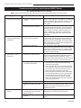
Troubleshooting - SIT NOVA 820 (SDDVT Series) ...........................................................32
Instructions for RF Comfort Control Valve (SDDVTC Series) ............................................
33
Fuel Conversion Instructions ..............................................................................................37
Maintenance Annual System Inspection ..................................................................................................41
Logset and Burner/Cleaning and Inspection ......................................................................
41
Care of Cast Iron ................................................................................................................41
Cleaning the Glass .............................................................................................................41
Glass Replacement ............................................................................................................
41
Gasket Replacement ..........................................................................................................42
Inspect the Vent System Annually ......................................................................................
42
Check the Gas Flame Regularly ........................................................................................42
Stove Disassembly .............................................................................................................42
Wiring Diagrams .................................................................................................................
43
Replacement Parts ...........................................................................................................................................44
Optional Accessories
..........................................................................................................................................47
Warranty ...........................................................................................................................................51
Table of Contents

3
Stardance Direct Vent/Natural Vent Gas Heater
20012734
General Information
The Stardance Direct Vent/Natural Vent Room Heater, Model
Nos. SDDVTCB, SDDVTEB, SDDVTMB, SDDVTBS, SDDVTCH,
SDDVTVG, SDDVTBD, SDDVTCCB, SDDVTCEB, SDDVTC-
MB, SDDVTCBS, SDDVTCCH, SDDVTCVG, SDDVTCCBD, is
a vented gas appliance listed to the ANSI standard Z21.88-2005
and CSA-2.33-2005 for Vented Room Heaters, and CSA 2.17-
M91, Gas-Fired Appliances For Use at High Altitudes.
The installation of the Stardance Direct Vent/Natural Vent Room
Heater must conform with local codes, or in the absence of lo
-
cal codes, with National Fuel Gas Code, ANSI Z223.1/NFPA 54
— latest edition and CSA B-149.1 Installation Code. (EXCEP
-
TION: Do not derate this appliance for altitude. Maintain the
manifold pressure at 3.5” w.c. for Natural Gas and 10.0” w.c. for
LP gas at maximum input.)
This appliance is only for use with the type of gas indicated on
the rating plate. This appliance is not convertible for use with
other gases unless a certified kit is used.
Installation and replacement of gas piping, gas utilization
equipment or accessories, and repair and servicing of
equipment shall be performed only by a qualified agency,
preferably NFI or WETT (Canada) certified. The term “quali-
fied agency” means any individual, firm, corporation, or
company that either in person or through a representative
is engaged in and is responsible for (a) installation or re-
placement of gas piping, or (b), the connection, installation,
repair, or servicing of equipment, who is experienced in
such work, familiar with all precautions required, and has
complied with all the requirements of the authority having
jurisdiction.
The Stardance Direct Vent/Natural Vent Room Heater should
be inspected before use and at least annually by a qualified
service agency. It is imperative that control compartments,
burners, and circulating air passageways of the appliance
be kept clean.
The Stardance Direct Vent/Natural Vent Room Heater and its
individual shut-off valve must be disconnected from the gas sup
-
ply piping during any pressure testing of that system at test pres
-
sures in excess of 1/2 psig (3.5 kPa).
The Stardance Direct Vent/Natural Vent Room Heater must be
isolated from the gas supply piping system by closing its indi
-
vidual manual shutoff valve during any pressure testing of the
gas supply piping system at test pressures equal to or less than
1/2 psig.
‘Direct Vent’ describes a sealed combustion system in which in
-
coming outside air for combustion and outgoing exhaust enter
and exit through two separate concentric passages within the
same sealed vent system. The system does not use room air to
support combustion. The Direct Vent system permits the gas ap-
pliance to be vented directly to the outside atmosphere through
the side of the house or vertically through the roof. Conventional
venting systems (Natural Vent) take air from the room for com
-
bustion and vent the exhaust vertically through the roof to the
atmosphere.
This appliance is approved for bedroom installations in the U.S.
and Canada.
This appliance may be installed in an aftermarket* manufactured
(mobile) home, where not prohibited by state or local codes.
WARNING: Operation of this heater when not connected to a
properly installed and maintained venting system can result
in carbon monoxide (CO) poisoning and possible death.
The Stardance Direct Vent/Natural Vent Room Heater, when in-
stalled, must be electrically grounded in accordance with local
codes or, in the absence of local codes, with the National Electri
-
cal Code ANSI/NFPA 70, (latest edition), or of the current Cana-
dian Electrical Code C22.1.
Due to high temperatures this appliance should be located
out of traffic and away from furniture and draperies.
WARNING: This appliance is hot while in operation. Keep
children, clothing, and furniture away. Contact may cause
burns or ignition of combustible materials.
Children and adults should be alerted to the hazards of high
surface temperatures and should stay away to avoid burns
or clothing ignition. Young children should be carefully su-
pervised when they are in the same room as the appliance.
Clothing or other flammable materials should not be placed
on or near the appliance.
Any safety screen, glass or guard removed for servicing
an appliance must be replaced prior to operating the appli
-
ance.
The appliance area must be kept clear and free from com
-
bustible materials, gasoline, and other flammable vapors
and liquids.
The flow of combustion and ventilation air must not be ob
-
structed. The installation must include adequate accessibil
-
ity and clearance for servicing and proper operation.
WARNING: Do not operate the Room Heater with the glass
panel removed, cracked or broken. Replacement of the pan
-
el should be done by a licensed or qualified service person.
Do not use this appliance if any part has been under water.
Immediately call a qualified service technician to inspect the
appliance and to replace any part of the control system and
any gas control which has been under water.
Do not burn wood, trash or any other material for which this
appliance was not designed. This appliance is designed to
burn either natural gas or propane only.
This gas appliance must not be connected to a chimney flue
serving a separate solid-fuel burning appliance.
CAUTION: Label all wires prior to disconnection when ser
-
vicing controls. Wiring errors can cause improper and dan-
gerous operation.
Verify proper operation after servicing.
* Aftermarket: Completion of sale, nor for purpose of resale, from the
manufacturer.
Proposition 65 Warning: Fuels used in gas, woodburning or
oil fired appliances, and the products of combustion of such
fuels, contain chemicals known to the State of California to
cause cancer, birth defects and other reproductive harm.
California Health & Safety Code Sec. 25249.6

4
Stardance Direct Vent/Natural Vent Gas Heater
20012734
Installation Requirements
Requirements for the Commonwealth of
Massachusetts
All gas fitting and installation of this heater shall only be
done by a licensed gas fitter or licensed plumber.
For all side wall horizontally vented gas fueled
equipment installed in every dwelling, building or
structure used in whole or in part for residential
purposes, including those owned or operated by the
Commonwealth and where the side wall exhaust
vent termination is less than seven (7) feet above
finished grade in the area of the venting, including
but not limited to decks and porches, the following
requirements shall be satisfied:
Installation of Carbon Monoxide Detectors
At the time of installation of the side wall horizontal
vented gas fueled equipment, the installing plumber
or gas fitter shall observe that a hard wired carbon
monoxide detector with an alarm is installed on each
additional level of the dwelling, building or structure
served by the side wall horizontal vented gas fueled
equipment. It shall be the responsibility of the property
owner to secure the services of qualified licensed
professionals for the installation of hard wired carbon
monoxide detectors.
In the event that the side wall horizontally vented gas
fueled equipment is installed in a crawl space or an
attic, the hard wired carbon monoxide detector with
alarm and battery back-up may be installed on the next
adjacent floor level.
In the event that the requirements of this subdivision
can not be met at the time of completion of installation,
the owner shall have a period of thirty (30) days
to comply with the above requirements; provided,
however, that during said thirty (30) day period, a
battery operated carbon monoxide detector with an
alarm shall be installed.
Approved Carbon Monoxide Detectors
Each carbon monoxide detector as required in
accordance with the above provisions shall comply with
NFPA 720 and ANSI/UL 2034 listed and IAS certified.
Signage
A metal or plastic identification plate shall be
permanently mounted to the exterior of the building at
a minimum height of eight (8) feet above grade directly
in line with the exhaust vent terminal for the horizontally
vented gas fueled heating appliance or equipment. The
sign shall read, in print size no less than one-half (1/2)
inch in size, “GAS VENT DIRECTLY BELOW, KEEP
CLEAR OF ALL OBSTRUCTIONS”.
Inspection
The state or local gas inspector of the side wall
horizontally vented gas fueled equipment shall not
approve the installation unless, upon inspection, the
inspector observes carbon monoxide detectors and
signage installed in accordance with the provisions of
248 CMR 5.08(2)(a)1 through 4.
Exemptions
The following equipment is exempt from 248 CMR
5.08(2)(a)1 through 4:
• The equipment listed in Chapter 10 entitled
“Equipment Not Required To Be Vented” in the most
current edition of NFPA 54 as adopted by the Board;
and
• Product Approved side wall horizontally vented gas
fueled equipment installed in a room or structure
separate from the dwelling, building or structure
used in whole or in part for residential purposes.
MANUFACTURER REQUIREMENTS
Gas Equipment Venting System Provided
When the manufacturer of Product Approved side
wall horizontally vented gas equipment provides a
venting system design or venting system components
with the equipment, the instructions provided by the
manufacturer for installation of the equipment and the
venting system shall include:
• Detailed instructions for the installation of the venting
system design or the venting system components;
and
• A complete parts list for the venting system design or
venting system.
Gas Equipment Venting System NOT Provided
When the manufacturer of a Product Approved side
wall horizontally vented gas fueled equipment does
not provide the parts for venting the flue gases, but
identifies “special venting systems”, the following
requirements shall be satisfied by the manufacturer:
• The referenced “special venting system” instructions
shall be included with the appliance or equipment
installation instructions; and
• The “special venting systems” shall be Product
Approved by the Board, and the instructions for
that system shall include a parts list and detailed
installation instructions.
A copy of all installation instructions for all Product
Approved side wall horizontally vented gas fueled
equipment, all venting instructions, all parts lists
for venting instructions, and/or all venting design
instructions shall remain with the appliance or
equipment at the completion of the installation.

5
Stardance Direct Vent/Natural Vent Gas Heater
20012734
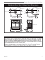
Stardance Direct Vent / Natural Vent Dimensions
26"
(680 mm)
25"
(654 mm)
14"
(355 mm)
3"
(76 mm)
C
L
12734
Stardance dim
8/07 djt
Supply Inlet
9"
(229 mm)
C
L
7" Outer Dia.
(178 mm)
Flue Collar
L
C
Supply Inlet
SDDVT Models
8"
(203 mm)
7" Outer Dia.
(178 mm)
Flue Collar
L
C
Supply Inlet
SDDVTC Models
7”
(197 mm)
8"
(222 mm)
2”
(73 mm)
12”
(321 mm)
2”
(73 mm)
12”
(321 mm)
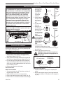
Attention
The Stardance stove is shipped from the factory as a Direct Vent Gas Heater. This heater
may be converted into a Natural Vent unit in the field. If a Natural Vent heater is desired,
the Vermont Castings Z31B00 FSDHAG Draft Hood must be directly installed to the top
of the unit according to the installation instructions. The Draft Hood Adapter is available
in the 7FSDHASK stove kit or as a separate item.
When the Stardance stove is converted to Natural Vent, it uses 4” vent pipe. For aes-
thetic purposes the CFM direct vent system may be used up to the ceiling.
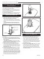
Fig. 1 Stardance dimensions.

6
Stardance Direct Vent/Natural Vent Gas Heater
20012734
Clearance Requirements
Minimum Clearances to Combustible
Materials
Measure side clearances as shown in Figures 3 and 4
from the outer edge of the cast iron stove top. Measure
rear clearances from the outermost surface of the steel
rear skirt.
The Stardance heater is approved for installation into
an alcove constructed of combustible materials to the
dimensions and clearances shown on the next page.
The same clearances apply in a standard parallel instal
-
lation.
Installation Requirements
The installation must conform with local codes or, in
the absence of local codes, with the National Fuel Gas
Code, ANSI Z223.1/NFPA 54 - latest edition. (EXCEP-
TION: Do not derate this appliance for altitude. Main-
tain the manifold pressure at 3.5 inches w.c. for Natural
Gas, and 10 inches w.c. for Propane).
In Canada, installation must be in accordance with the
current CSA B-149.1 Installation Codes and/or local
codes.
The installation should be done by a qualified ser
-
vice person who is familiar with the building codes
and installation techniques appropriate for your
area to accomplish a safe and effective installation.
Your dealer or your local gas supplier will be able to
refer a qualified service person.
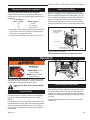
WARNING: Due to high temperatures, the
HEATER should be located out of traffic
and away from furniture and draperies.
The surface of the Heater Is hot when it is in use.
Young children should be watched carefully when
they are in the same room when the Heater is in
use, and they should be taught to avoid the hot
surface. Keep any objects that can burn well away
from the Heater, and observe the recommended
clearances that follow.
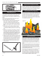
A
B
E
C
D
ST207a
Stardance
Stove locations
9/28/00 djt
Fig. 2 Possible stove locations.
ST207
Warning:
• Always maintain required clearances
(air spaces) to nearby combustibles to prevent
fire hazard. Do not fill air spaces with insula-
tion. All venting components must maintain a
1” (25 mm) clearance to combustible materials.
Maintain a 6” (150 mm) clearance when using a
single wall pipe.
• The gas appliance and vent system must be
vented directly to the outside of the building
and never be attached to a chimney serving a
separate solid fuel or gas-burning appliance.
Each direct vent appliance must use its own
separate vent system. Common vents are pro-
hibited.
• Refer to the manufacturer’s instructions in
-
cluded with the venting system for complete
installation procedures.
�
Locating the Stove
In choosing a location for the stove, consider:
• The location of outside walls;
• Where additional heat is needed:
• Where family members gather most often;
• The vent system requirements.
NOTE: We do not recommend the use of wallpaper
next to this stove. Over time, radiant heat may cause
the wallpaper to shrink, or may adversely affect the
binders in the wallpaper adhesive.

7
Stardance Direct Vent/Natural Vent Gas Heater
20012734
ST128b
Stardance
flue centerline
9/28/00 djt
C
L
C
L
B
D
C
A
Parallel Installation: Minimum Clearance
and Flue Centerline, Direct Vent and
Natural Vent
ST128b
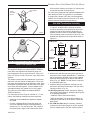
Stove Clearances: A: 4” (102 mm)
B: 4” (102 mm)
Pipe Centerlines: C: 15¹⁄₂” (395 mm)
D: 9” (229 mm)
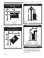
Fig. 3 Parallel installation, minimum back and side clear-
ances, and flue centerlines.
Corner Installation:
Minimum Clearance and Flue Centerline,
Direct Vent and Natural Vent
ST129b
Stardance
corner specs
9/28/00 djt
A
A
B
B
Stove Clearance: A: 4” (102 mm)
Pipe Centerline: B: 14¹⁄₂” (370 mm)
ST129b
Fig. 4 Corner installation, minimum corner clearance and flue
centerline.
Wall Centerline from Floor
ST131b
Stardance
wall thimble
9/28/00 djt
A
Direct Vent Only
ST131b
Effective Minimum
Wall Thimble 56” (1480 mm) (CFM Pipe)
Centerline 52” (1378 mm) (Simpson Duravent Pipe)
Fig. 5 Minimum wall thimble centerline.
Wall and Ceiling Clearances
A
C
D
ST101b
Stardance
Direct Vent
Min. Clrnc
9/28/00 djt
B
ST101b
A: Rear Wall 4” (102 mm)
B: Min. Clearance 45¹⁄₄” (1154 mm)*
C: Min. Alcove Height 72” (1830 mm)
D: Max. Alcove Depth 48” (1220 mm)
Sidewall Clearance 4” (102 mm)
Fig. 6 Dimensions and clearances to ceiling or alcove.
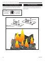
Hearth Requirements
The Stardance Heater must be installed on rigid floor
-
ing. When the heater is installed directly on any com-
bustible surface other than wood flooring, a metal or
wood panel extending the full width and depth of the
unit must be used as the hearth. There are no other
hearth requirements.

8
Stardance Direct Vent/Natural Vent Gas Heater
20012734
Weight: Fully assembled; 202 lbs.
Gas Inlet and Manifold Pressures
Natural LP (Propane)
Inlet Minimum 5.5” w.c. 11.0” w.c.
Inlet Maximum 14.0” w.c. 14.0” w.c.
Manifold Pressure 3.5” w.c. 10” w.c.
Stardance Direct Vent / Natural Vent
Certified to:
ANSI Z21.88-2005 / CSA 2.33-2005
Vented Gas Fireplace Heaters
The installation of your Vermont Castings stove must
conform with local codes, or in the absence of local
codes, with the National Fuel Gas Code ANSI Z223.1/
NFPA 54 - latest edition, or CSA B149.1 Installation
code. (EXCEPTION: Do not derate this appliance for
altitude up to 4,500 feet (1,370m). Maintain the mani-
fold pressure at 3.5” w.c. for Natural Gas and 10.0”
w.c. for LP Gas.
High Elevations
Input ratings are shown in BTU per hour and are cer-
tified without deration for elevations up to 4,500 feet
(1,370m) above sea level.
For elevations above 4,500 feet (1,370m) in USA,
installations must be in accordance with the current
ANSI Z223.1/NFPA 54 and/or local codes having
jurisdiction.
In Canada, please consult provincial and/or local au-
thorities having jurisdiction for installations at eleva-
tions above 4,500 feet (1,370m).
WARNING: Improper installation, adjustment,
alteration, service or maintenance can cause in-
jury or property damage. Refer to this manual for
correct installation and operational procedures.
For assistance or additional information consult
a qualified installer, service agency, or the gas
supplier.
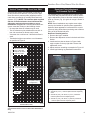
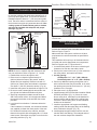
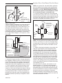
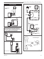
Horizontal Termination -
Direct Vent ONLY
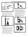
The vent must rise vertically a minimum of 24” (610mm)
off the top of the unit, before the first elbow. The hori-
zontal run may extend up to 20’ (6m) and include a
vertical rise of up to 40’ (12m). (Fig. 7) Horizontal
termination must also meet the criteria shown in Figures
9 through 11.
• Approved vent systems must terminate above and
including the heavy line in Figure 7.
• Two 45˚ elbows may be substituted for each single
90˚ elbow.
• With a rise between 2’ - 5’, one 90˚ or two 45˚ el
-
bows may be used.
20
19
18
16
15
14
13
12
11
10
9
8
7
6
5
4
3
2
1
0
1 2 3 4 5 6 7 8 9
10 11 12 13 14 15 16 17 18 19 20
Vertical Run (in feet)
(Measured from the appliance flue collar to the top of the vent pipe.)
Horizontal Run (in feet)
21
22
23
24
25
26
27
28
29
30
31
32
33
34
35
36
37
38
39
40
ST134a
FDV28
Horizontal
vent run
12/3/99 djt
areas modified
1/11/00 djt
ST134a
Fig. 7 Horizontal vent termination window.
May use up to
three 90° Elbows
One 90°
Elbow
Unacceptable
Venting Configureation
Gas Specifications
Max. Min.
Input Input
Model Fuel Gas Control BTU/h BTU/h
SDDVT Series Nat Millivolt 28,000 20,000
SDDVT Series Prop Millivolt 28,000 20,000
SDDVTC Series Nat Comfort Control 28,000 22,000
SDDVTC Series Prop Comfort Control 28,000 22,000
Air Shutter Setting
Minimum rear injector air inlet openings.
Model Natural Gas LP
Direct Vent 1/2” Open 1/2” Open
Natural Vent 1/2” Open 1/2” Open

9
Stardance Direct Vent/Natural Vent Gas Heater
20012734
Vertical Termination - Direct Vent ONLY
A vertical vent system must terminate no less than 8’
(2.44m) and no more than 40’ (12m) above the appli-
ance flue collar. A restrictor plate (supplied) must be
used where specified in all vertically terminated vent
systems. (Fig. 8) NOTE: The restrictor plate supplied
with the vertical termination should be discarded.
Adjust the restrictor plate according to recom-
mendations in Figure 10. A vertically terminated vent
system must also conform to the following criteria:
• No more than three 90˚ elbows may be used.
• Two 45˚ elbows may be substituted for one 90˚ el
-
bow. No more than six elbows may be used.
• Vent must rise a minimum of 2 feet before offset is
used.
• Termination height must conform to roof clearance
as specified in Figure 9.
Vertical Run (in feet)
(Measure from the appliance flue collar to the top of the vent pipe.)
Horizontal Run (in feet)
ST132b
FDV28
Vertical
vent run
1/08
ST132b
Fig. 8 Vertical vent termination window.
*The restrictor Plate is used on Direct Vent Installations
Only.
All Vertical Termina-
tions in this area
Require use of the
Restrictor Plate*
Vertical Terminations
must be within this
area
Unacceptable Venting
Configuration
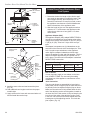
Restrictor Plate Adjustment
for Extended Pipe Runs
The Stardance stove is shipped with a restrictor plate
in the Parts Bag. Adjustments can be made by loosen-
ing the adjustment screw to allow the restrictor plate to
slide up or down. (Fig. 9) A guide for usage is shown in
Figure 10.
NOTE: Some installations may require some adjust-
ment by the installer for optimum flame appearance.
Optimum flame appearance is a flame that is not sub-
ject to tall, dirty yellow flames producing soot or flames
lifting off of the ember bed ports.
Restrictor Plate Adjustment
1. Remove the logs if installed.
2. Remove the adjustment screw in the back wall of the
firebox.
3. Install restrictor plate as shown in Figure 9 with
angle on plate on the top right side. Secure with
adjustment screw.
4. Adjust restrictor according to examples in Figure 10.
5. Install logs following log installation instructions.
Figure 10
Examples for Extended Run/Restrictor Plate Settings
1. Vertical 40’ (12 m) - restrictor plate lowered completely
down
2. Vertical 20’ (6 m), 90° elbow, 8’ (2.4 m ) horizontal -
restrictor plate lowered completely down
3. Vertical 10’ (3 m), 90° elbow, 2’ (305 mm) horizontal
- restrictor plate lowered completely down
Restrictor Plate
ST936
Fig. 9 SDDVT/SDDVTC restrictor plate.
No Restrictor
Plate

10
Stardance Direct Vent/Natural Vent Gas Heater
20012734
When planning the installation, consider the location
of the vent terminal and clearances. Some of the most
common clearances to keep in mind are shown in
Figure 11.
Important: All vent clearances must be maintained.
Check your vent termination clearances against
Figures 11 through 13.
The vent should be placed so that people cannot be
burned by accidentally touching the vent surfaces when
the stove is operating.
The vent termination should be located where it cannot
be damaged by such things as automobile doors, lawn
mowers or snowblowers and it should be located away
from areas where it could become blocked by snow,
etc.
Some considerations are:
• Obstructions or impediments to venting.
• Nearby combustible materials that could come into
contact with combustion exhaust gases.
• Other nearby openings {within 12” (305 mm)}
through which exhaust gas could reenter the build-
ing.
• All vegetation within 3’ (76 mm) that may interfere
with the draft.
Other factors that influence where the installation will
be sited include the location of outside walls, where
additional heat may be desired in the home, where the
family members gather most regularly, and perhaps
most importantly, the distance limitations of the venting
system.
IMPORTANT
Direct Vent Only
• The horizontal termination must not be recessed
into the exterior wall or siding.
• Horizontal vent runs must be level toward the vent
termination.
• Clearances around the vent termination must be
maintained.
• For installations using Simpson DuraVent pipe,
parallel installations with minimum wall clearance
have restricted access for connecting the Hori-
zontal Vent Cap straps to the vent pipe. See the
maker’s instructions for recommended installation
procedures.
Vent Termination Clearances
Your stove is approved to be vented either through the
side wall, or vertical through the roof.
• CFM Corporation does not require any opening for
inspection of vent pipe.
• Only CFM Corporation and Simpson DuraVent vent-
ing components specifically approved and labelled
for this stove may be used.
• Minimum clearances between vent pipes and com-
bustible materials is one (1”) inch (25 mm), except
where stated otherwise.
• Venting terminals shall not be recessed into a wall or
siding.
• Horizontal venting must be installed on a level plane
without an inclining or declining slope.
There must not be any obstruction such as bushes,
garden sheds, fences, decks or utility buildings within
24” from the front of the termination hood.
Do not locate termination hood where excessive snow
or ice build up may occur. Be sure to check vent termi-
nation area after snow falls, and clear to prevent ac-
cidental blockage of venting system. When using snow
blowers, make sure snow is not directed towards vent
termination area.
Location of Vent Termination
It is imperative the vent termination be located observ-
ing the minimum clearances as shown on this page.

11
Stardance Direct Vent/Natural Vent Gas Heater
20012734
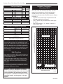
General Venting Information - Termination Location
V
V
V
V
V
V
V
X
X
X
D
E
B
B
B
C
B
M
B
A
J
K
F
L
VENT TERMINATION AIR SUPPLY INLET
AREA WHERE TERMINAL IS NOT PERMITTED
H
I
Operable
Operable
Fixed
Closed
V
B
CFM145a
DV Termin Location
5/01/01 Rev. 12/05/01
sta
INSIDE
CORNER DETAIL
V
A
G
N
N
CFM145a
A = Clearance above grade, veranda, porch, 12” (30cm) 12” (30cm)
deck, or balcony
B = Clearance to window or door that may be 6” (15cm) for appliances 6” (15cm) for appliances
opened < 10,000Btuh (3kW), 12” (30cm) < 10,000 Btuh (3kW), 9”
for appliances > 10,000 Btuh (3kW) and (23cm) for appliances > 10,000
< 100,000 Btuh (30kW), 36” (91cm) Btuh (3kW) and < 50,000 Btuh
for appliances > 100,000 Btuh (30kW) (15kW), 12” (30cm) for
appliances > 50,000 Btuh (15kW)
C = Clearance to permanently closed window 12” (305mm) recommended to 12” (305mm) recommended to
prevent window condensation prevent window condensation
D = Vertical clearance to ventilated soffit located
above the terminal within a horizontal 18” (458mm) 18” (458mm)
distance of 2’ (610mm) from the center
line of the terminal
E = Clearance to unventilated soffit 12” (305mm) 12” (305mm)
F = Clearance to outside corner see next page see next page
G = Clearance to inside corner (see next page) see next page see next page
H = Clearance to each inside of center line 3’ (91cm) within a height of 15’ (5m) 3’ (91cm) within a height of 15’
extended above meter/regulator assembly above the meter/regulator assembly (5m) above the meter/regulator
assy
I = Clearance to service regulator vent outlet 3’ (91cm) 3’ (91cm)
J = Clearance to nonmechanical air supply inlet 6” (15cm) for appliances < 10,000 6” (15cm) for appliances
to building or the combustion air inlet to any Btuh (3kW), 12” (30cm) for < 10,000 Btuh (3kW), 9”
other appliances appliances > 10,000 Btuh (3kW) and (23cm) for appliances > 10,000
< 100,000 Btuh (30kW), 36” (91cm) Btuh (3kW) and < 50,000 Btuh
for appliances > 100,000 Btuh (30kW) (15kW), 12” (30cm) for
appliances > 50,000 Btuh (15kW)
K = Clearance to a mechanical air supply inlet 6’ (1.83m) 3’ (91cm) above if within 10
feet (3m) horizontally
L = Clearance above paved sidewalk or paved 7’ (2.13m)† 7’ (2.13m)†
driveway located on public property
M = Clearance under veranda, porch, deck or 12” (30cm)‡ 12” (30cm)‡
balcony
N = Clearance above a roof shall extend a minimum of 24” (610mm) above the highest point when it passes through the roof
surface, and any other obstruction within a horizontal distance of 18” (450mm).
1 In accordance with the current CSA-B149 Installation Codes
2 In accordance with the current ANSI Z223.1/NFPA 54 National Fuel Gas Codes
† A vent shall not terminate directly above a sidewalk or paved driveway which is located between two single family dwellings and
serves both dwellings
‡ only permitted if veranda, porch, deck or balcony is fully open on a minimum 2 sides beneath the floor:
NOTE: 1. Local codes or regulations may require different clearances.
2. The special venting system used on Direct Vent units are certified as part of the appliance, with clearances tested and
approved by the listing agency.
3. CFM Corporation assumes no responsibility for the improper performance of the appliance when the venting system does not
meet these requirements.
Canadian Installations
1
US Installations
2
Fig. 11 Vent termination clearances.

12
Stardance Direct Vent/Natural Vent Gas Heater
20012734
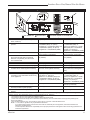
Fig. 12 Termination clearances.
Venting Requirements - Natural Vent Only
FP567
NVBR/NVBC VENTING RUNS
11/12/97
Venting Runs
Horizontal Run (in feet)
Vertical Run (in feet)
(Measured from top of the unit before any elbow)
A: Vertical installations up to 36 feet (12m) in
height. Up to an 18 ft. horizontal vent run can be
installed within the vent system using a
maximum of two 90-degree elbows or four
45-degree elbows.
B: Vertical installations up to 36 feet (12m) in
height. Up to a 24 ft. horizontal vent run can be
installed within the vent system using a
maximum of two 45-degree elbows.
(Ratio = 2/3, Hor./Vert.)
= Acceptable venting configuration
= Unacceptable venting configuration
A
B
NOTE: When venting staight vertical, without any
elbow, a minimum of 8 ft. vertical is required
off the top of the stove.
Fig. 13 Vent termination window - Natural Vent ONLY.
NOTE: When using the FSDHAG, the restrictor plate
supplied with the stove is not used.
Outside Corner
Inside Corner
Termination Clearances
Termination clearances for buildings with combustible and noncombustible exteriors.
G =
Combustible
6" (152 mm)
Noncombustible
2" (51 mm)
F =
Combustible
6" (152 mm)
Noncombustible
2" (51 mm)
G
Balcony -
with no side wall
M =
Combustible &
Noncombustible
12" (305 mm)
M
Balcony -
with perpendicular side wall
M = 24" (610 mm)
P = 20” (508 mm)
M
F
Alcove Applications*
C
D
C
E
V
V
Combustible &
Noncombustible
V
V
V
E = Min. 6” (152 mm) for
non-vinyl sidewalls
Min. 12” (305 mm) for
vinyl sidewalls
O = 8’ (2.4 m) Min.
O
P
584-15
No.
of Caps D
Min.
C
Max.
1 3’ (914 mm) 2 x D
Actual
2 6’ (1.8 m) 1 x D
Actual
3 9’ (2.7 m) 2/3 x D
Actual
4 12’ (3.7 m) 1/2 x D
Actual
D
Min.
= # of Termination caps x 3
C
Max.
= (2 / # termination caps) x D
Actual
*NOTE: Termination in an alcove space (spaces open only on one side and with an overhang) is permitted with the dimensions
specified for vinyl or non-vinyl siding and soffits. 1. There must be a 3’ (914 mm) minimum between termination caps. 2. All
mechanical air intakes within 10’ (1 m) of a termination cap must be a minimum of 3’ (914 mm) below the termination cap. 3. All
gravity air intakes within 3’ (914 mm) of a termination cap must be a minimum of 1’ (305 mm) below the termination cap.

13
Stardance Direct Vent/Natural Vent Gas Heater
20012734
Venting Requirements and Options -
Direct Vent ONLY
Approved Vent System Components
The Stardance Heater must be vented to the outdoors
through an adjacent exterior wall or through the roof.
The venting system must be comprised of the appropri-
ate listed venting components specified on this page.
These parts are available from DuraVent Corporation,
Selkirk Corporation or your Vermont Castings Dealer.
See Figure 4 for dimensions relevant to the standard
minimum-vent kits.
Simpson DuraVent Components
www.duravent.com
Phone: 1-800-835-4429, Fax: 1-707-446-4740
Minimum Horizontal Vent Kit 2792
Starter Pipe Assembly (incl. inner & outer sections) 2768*
90° Elbow, Blk. 46DVA-E90B*
45° Elbow, Gal. 46DVA-E45
6” Straight, Blk. 46DVA-06B*
9” Straight, Blk. 46DVA-09B
11” - 14⁵⁄₈” Adjustable Straight Section 46DVA-08AB
12” Straight 46DVA-12
24” Straight 46DVA-24B*
36” Straight 46DVA-36B
48” Straight 46DVA-48
Horizontal Vent Cap 46DVA-HC*
Wall Plate 46DVA-DC
Vinyl Siding Shield 46DVA-VSS
Snorkel Termination - 14” 46DVA-SNK14
Snorkel Termination - 36” 46DVA-SNK30
Wall Strap 46DVA-WS
Cathedral Ceiling Support Box 46DVA-CS
Storm Collar 46DVA-SC
Firestop Spacer 46DVA-FS
Flashing 0/12 - 6/12 46DVA-F6
Flashing 6/12 - 12/12 46DVA-F12
Steel Chimney Conversion Kit
Kit A (6
⁵⁄₈” - 8⁵⁄₈”) 46DVA-KCA
Kit B (6⁵⁄₈” - 10¹⁄₂”) 46DVA-KCB
Kit C (6⁵⁄₈” - 13”) 46DVA-KCC
Masonry Chimney Conversion Kit 46DVA-KMC
Vertical Termination Cap (High Wind) 46DVA-VCH
Vertical Termination Cap (Low Profile) 46DVA-VC
*Included in Minimum Horizontal Vent Kit #2792
All DuraVent Straight vent pipe sections have a net
length 1¹⁄₂” (37mm) less than the nominal dimension;
i.e., a 6” (152mm) Straight pipe section has an effective
length of 4¹⁄₂” (115mm).
Selkirk Corporation Vent Components
www.selkirkcorp.com
1301 W. President George Bush Highway Ste. 330
Richardson, TX 75080
Phone: 1-800-992-8368, Fax: 1-877-393-4145
Appliance Adapter 4DT-AAV
90° Elbow, Blk. 4DT-EL90B
45° Elbow, Blk. 4DT-EL45B
6” Straight, Blk. 4DT-06B
9” Straight, Blk. 4DT-09B
4” - 10” Adjustable Straight Section Blk. 4DT-AJ12B
12” Straight, Blk. 4DT-12B
18” Straight, Blk. 4DT-18B
24” Straight, Blk. 4DT-24B
36” Straight, Blk. 4DT-36B
48” Straight, Blk. 4DT-48B
Horizontal Termination 4DT-HC
Wall Thimble 4DT-WT
Vinyl Siding Standoff 4DT-VS
Snorkel Termination - 14” 4DT-ST14
Snorkel Termination - 36” 4DT-ST36
Wall Support Band 4DT-WS/B
Cathedral Ceiling Support Box 4DT-CCS
Storm Collar 4DT-SC
Firestop Spacer 4DT-FS
Flashing 0/12 - 6/12 4DT-AF6
Flashing 6/12 - 12/12 4DT-AF12
Steel Chimney
Horizontal Kit A 4DT-HKA
Horizontal Kit B 4DT-HKB
Vertical Kit 4DT-VKC
Masonry Chimney Kit 4DT-MCK
Vertical Termination Cap 4DT-VC
NOTE: Direct vent pipe may be used on the Natural
Vent system from the top of the draft hood adapter to
the ceiling.

14
Stardance Direct Vent/Natural Vent Gas Heater
20012734
CFM Vent Components
The following kits are available to meet the needs of
most installations. All pipe has a 7” outer diameter and
includes a 4” diameter inner section. A (CG) designa-
tion indicates the part is finished in Charcoal Gray paint.
Consult your dealer about other vent parts that may be
appropriate to complete the installation.
Min. Through the Wall Vent Kit 7TFSSK
(1) 90-Degree Elbow (CG)
(1) 24” Straight pipe (CG)
(1) 24” - 42” Adjustable Straight Pipe
(1) Side Wall Termination
(1) Firestop
(1) Zero-clearance sleeve
(1) Hardware package
(1) Finishing plate (CG)
(1) Finishing collar (CG)
(4) Charcoal Gray flue pipe rings
Starter Kit for Below Grade Installation 7TDVSKS
(1) Snorkel Termination (7TDVSNORK)
Vertical Termination Kit, 1/12-6/12 Pitch 7TDVSKVA
(1) Combination Horizontal Offset / Roof Support
(1) Vertical Termination
(1) Storm Collar
(1) 1/12-6/12 Flashing
(1) Finishing Plate (CG)
(1) Finishing Collar (CG)
(1) Polished Brass Flue Pipe Ring
(1) Hardware Package
Vertical Termination Kit, 7/12-12/12 Pitch 7TDVSKVB
(1) 7/12 - 12/12 Flashing
and all of the other Vertical Termination parts.
Vertical Termination, Flat Roof 7DVSKVF
(1) Flat Flashing
and all of the other Vertical Termination parts.
Twist Lock 12” Straight Pipe (CG) 7TFSDVP12
(1) 12” Non-adjustable Pipe
Twist Lock 12”-18” Straight Pipe (CG) 7TFSDVP1218
(1) 12” - 18” Adjustable Pipe
Twist Lock 24” Straight Pipe (CG) 7TFSDVP24
(1) 24” Non-adjustable Pipe
Twist Lock 48” Straight Pipe (CG) 7TFSDVP48
(1) 48” Nonadjustable Pipe
Twist Lock 45-Degree Elbow (CG) 7TFSDVT45
for vertical offsets
(1) 45-degree Elbow
Draft Hood Adapter FSDHAG
NV Stove Kit 7FSSK
(1) 7” Diameter Polished Brass Trim Ring
(1) 48” Nonadjustable Pipe (CG)
(1) 24” Nonadjustable Pipe (CG)
(1) Finishing Plate
(1) Finishing Collar (CG)
(1) 90 Degree Elbow (CG)
Stove Kit 7FSDHASK
Includes all parts in the 7FSSK plus the Draft Hood Adapter
FSDHAG
Combination Offset/Roof Support 7DVCS
Attic Insulation Shield 7DVAIS
7” Charcoal Gray Pipe Rings, (4) 7FSDRG
7” Polished Brass Pipe Rings (4) 7FSDRP
Wall Thimble 942G
NOTE: Direct vent pipe may be used on the Natural
Vent system from the top of the draft hood adapter to
the ceiling.

15
Stardance Direct Vent/Natural Vent Gas Heater
20012734
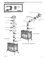
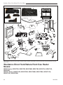
Install the Optional Fan
If you are installing the optional convection Fan Kit
#2767 (FK26), continue here. If you are not installing a
Fan Kit, go to Page 16, Venting System Assembly.
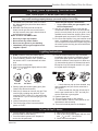
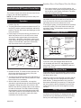
1. The fan kit includes a Blower Assembly and a Rheo-
stat Assembly, connected by a cable. (Fig. 14) The
Blower Assembly mounts to the bottom rear of the
stove, and the Rheostat mounts to the valve bracket
to the left of the valve. The assembly includes a
‘snapstat’ which automatically turns the fan On (or
Off) above (or below) approximately 109˚. The Rheo-
stat also provides a range of fan speed settings from
Off (which overrides the snapstat function) to High.
Unpack and inspect the Blower assembly. Confirm
the fan spins freely.
WARNING
This appliance is equipped with a three-prong
(grounded) plug for your protection against shock
hazard and should be plugged directly into a prop-
erly grounded three-prong receptacle. Do not cut or
remove the grounding prong from this plug.
4. The rheostat control switch attaches to the left side
of the valve bracket at the front of the stove. (Fig. 17)
• Remove retaining nut from shaft of rheostat. (if
preinstalled)
• Insert the rheostat through the hole in the back
of the left side of the valve bracket, aligning the
locator pin with the smaller hole in that bracket.
• Thread the retaining nut onto the shaft of the
rheostat, tightening with a wrench. Do not over-
tighten.
• Attach the control knob to the rheostat shaft.
• Use the wire tie to secure the fan and rheostat
wire harnesses together.
ST473
Fan parts
#2767 FK26
9/29/00
Not Used on RF Models
Not Used on
Stardance
Snapstat Bracket
Snapstat/
Extension
Assembly
Rheostat
Assembly
Not Used
on RF
Models
Connect to PC Board on
RF Models Only
Blower
Assembly
ST473
Fig. 14 Fan kit components.
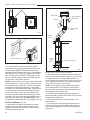
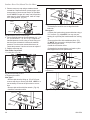
2. Remove the rear skirt insert panel at the bottom of
the Rear Skirt (Fig. 15) and fasten the blower assem-
bly to the firebox back with the two Phillips pan-head
bolts originally installed in the firebox back. (‘1’, Fig.
16)
NOTE: Steps 3 and 4 do not apply when the RF
valve is used. After attaching blower assembly to the
firebox, run the spliced female leads to the front of
the stove and attach to back of RF valve. (Page 34,
Fig. 58)
3. Attach the snapstat assembly to the snapstat bracket
with two sheet-metal screws. (‘2’, Fig. 16) Attach the
snapstat bracket to the stove with a hex-head bolt
passing through the bracket and into the stove base.
(‘3’, Fig. 16)
ST313
fk26
install fan kit
rear skirt insert
1/24/00
Rear Skirt
Sheet Metal
Screws
Rear Skirt
Insert
ST313
Fig. 15 Remove rear skirt insert.
ST314
Fk26ce
attach fan
1/24/00
Star Washer
Sheet Metal Screws
Phillips
Pan Head
Bolts
Star
Washer
NOTE: Shown
without shell for
clarification
Snapstat
Bracket
Snapstat
1/4” - 20
Hex Bolt
3
2
1
ST314
Fig. 16 Attach the fan assembly and the snapstat.
ST347a
JUV
FK28
rheostat install
9/21/00
Rheostat Retaining
Collar
Rheostat Knob
ST347a
Fig. 17 Attach the fan rheostat.

16
Stardance Direct Vent/Natural Vent Gas Heater
20012734
Venting System Assemlby - Direct Vent
General Information
The Stardance is approved for installation only with the
vent components listed on Pages 13 & 14. Follow the
vent component instructions exactly.
For U.S. installations: The venting system must con-
form with local codes and/or the current National Fuel
Gas Code, ANSI Z223.1/NFPA 54.
For Canadian installations: The venting system must
conform to the current CSA B149.1 installation code.
Install the Vent Adapter Pipe
(CFM Corporation Vent Components)
1. Attach Inner Starter Pipe, (found in the parts
bag), to the next section of inner pipe.
• Run a bead of sealant about 1/2” from the upper
end of the Inner starter pipe and join the two sections
together.
• Drill three pilot holes into the Inner Starter and
secure the assembly with three sheet metal screws.
(Fig. 18)
ST211
attach inner pipe
to next section
12/4/99 djt
CEMENT
First Section of Vent
Pipe
3” Inner
Starter PIpe
#8 x 1/2” Sheet
Metal Screws
ST211
Fig. 18 Connect the inner starter with the next section of in-
ner vent pipe.
ST212a
attach inner assy
no restrictor plate
6/07 djt
CEMENT
ST212a
Fig. 19 Attach inner assembly to flue collar.
Install the Vent Adapter Pipe
(Simpson Dura-Vent Components)
1. Discard the inner starter pipe shipped with the
stove. Using the starter pipe assembly listed on
Page 7, slide the inner section out to allow access.
• Run a bead of sealant around the bottom end of
the starter pipe and attach the assembly to the stove
using three 1/4-20 x 3/8” Phillips screws provided in
the parts bag. (Fig. 21)
2. Install the Outer Adapter Pipe. Apply a 1/4” bead of
cement around the outside surface, about one inch
from the crimped end. (Fig. 22) Orient the vertical
seam to the rear, and insert the crimped end of the
outer pipe into the flue collar. Fasten with three sheet
metal screws provided.
ST213
install outer adpater
12/6/99 djt
ST213
Fig. 20 Fasten outer pipe with #12 x 1/2” sheet metal screw.
2. Dry fit the Inner Pipe assembly to the stove for
the purpose of determining the center line of the
pipe on the wall.
• Side Wall Terminations: Dry fit the outer elbow
with the vertical outer vent and confirm the centerline
alignment with the wall thimble opening.
3. Attach the Inner Vent Assembly to the stove.
• Run a bead of sealant around the bottom end of
the starter pipe and attach the assembly to the stove
using three 1/4-20 x 3/8” Phillips screws provided in
the parts bag. (Fig. 19)
4. Install the Outer Adapter Pipe. Apply a 1/4” bead
of cement around the inside wall of the pipe, about
1” from the end. Insert the pipe over the stove flue
collar, keeping the vertical seam oriented to the back
of the stove. Also, be sure to align holes on the pipe
with the holes on the flue collar of the firebox. Fasten
the pipe to the holes in the flue collar with the #12 x
1/2” sheet metal screws provided. (Fig. 20)

17
Stardance Direct Vent/Natural Vent Gas Heater
20012734
ST355b
dura vent
attach inner assy
no restrictor plate
6/07 djt
CEMENT
1/4-20 x
3/8 Phillips
Screws
Inner Adapter
Pipe
ST355b
Fig. 21 Simpson Dura-Vent - install inner adapter pipe.
ST356
dura v
ent
attach outer assy
4/7/00 djt
ST356a
Fig. 22 Simpson Dura-Vent - install outer adapter pipe.
Side Wall Termination Assembly
1. Locate the vent opening on the wall. Refer to Page
7, Figure 6, to determine the opening centerline.
It may be necessary to first position the stove and
measure to find the hole location. Depending on
whether the wall is made of combustible materials,
cut the opening to the size shown in Figure 24. Com-
bustible wall openings must be framed as shown in
Figure 23.
VO584-100
Vent Opening
2/99 djt
CFM System
9³⁄₈”
(240mm)
9³⁄₈”
(240mm)
Combustible Wall
Framing Detail
DuraVent
System
10”
(254 mm)
7¹⁄₂”
(191 mm)
Noncombustible Wall
VO584-100
Fig. 23 Locate vent opening.
Install Vent Adapter Pipe
(Selkirk Corporation Vent Components)
The appliance adapter (AA) adapts DIRECT-TEMP to
most direct vent appliances incorporating outlet col-
lars configured to receive most common 4” (ID) by 6⁵⁄₈”
(OD) or 5” (ID) by 8” (OD) “Twist Lock” style, direct vent
systems.
The adapter incorporates two indentations on the outer
wall of the inlet end, which are designed to “Twist Lock”
into place upon attachment to the appliance outlet. Align
the adapter indentations with the entry slots of the appli-
ance outlet and slide together. Turn the adapter clock-
wise approximately one-quarter turn to lock in place.
The outlet end of the adapter is standard DIRECT-
TEMP construction.
For connection of Direct-Temp to units with 4” x 7” flue
outlets, the following methods have been approved:
• Install the Universal/Napoleon Appliance Adapter
4DT-AAN.
• Connect a standard Direct-Temp pipe length (do
not use an adjustable length in this application) a
minimum of 1¹⁄₂” over the flue outlet. The outside of
the Direct-Temp Length will fit inside the flue outlet
Secure with a minimum of two #8 x 1/4” sheet metal
screws and seal with hi-temp silicone.
For units factory equipped with appliance adapters from
other brands of Direct Vent systems, it is permissible
to simply slide a length of DT pipe over the appliance
adapter. Secure with a minimum of two #8 x 1/4” sheet
metal screws and seal with hi-temp silicone.
2. Measure the wall thickness and cut the wall sleeve
sections to proper length (MAXIMUM 12”). Assemble
the sleeve with the #8 sheet metal screws supplied.
Attach the firestop plate to the sleeve end with the
holes. (Fig. 24) NOTE: The wall sleeve is required
in combustible walls only.
3. Install the Wall Firestop/Sleeve assembly into the
wall cutout and fasten the firestop to the wall cutout
framing members. (Fig. 24)
For DuraVent pipe only: Install vent pipe by aligning
the locking system together, sliding the pipes togeth-
er and twisting clockwise.
• Install 90° elbow. Twist lock as before.
• Slide the wall plate over horizontal run before at
-
taching the horizontal run to the elbow. Fasten wall
plate to wall.
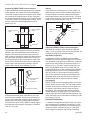
4. For CFM Vent Pipe only: If necessary, measure
to determine the vertical length (X) of pipe required
from the adapter pipe to the wall cutout centerline,

18
Stardance Direct Vent/Natural Vent Gas Heater
20012734
including a 2” overlap at the joint. (Fig. 25) use a
hacksaw or tin snips to trim the pipe as needed.
5. Install first the inner then the outer straight pipe
section(s), trimmed end down, to the point of the el-
bow. Drill 3 holes through each joint and fasten with
sheet metal screws.
ZCS103
Zero Clearance Sleeve
& Firestop
12/6/99 djt
12”
(305 mm)
Max. Length
Sleeve
#8 Sheet
Metal Screws
Firestop
ZCS103
Fig. 24 Assemble the wall sleeve and firestop.
ST214a
measure vertical vent
12/6/99 djt
X
ST214a
Fig. 25 Determine the vertical pipe length.
sheet metal screws. Slide the trim collar up against
the wall plate to cover the screws. (Fig. 27)
10. For both CFM and DuraVent Systems: Install
the vent terminal. (Fig. 28) Apply high temperature
sealant one inch from the ends of the inner and outer
collars. Guide the inner and outer vent termination
collars into the adjacent pipes. Double check that
the vent pipes overlap the collars by 2”. Fasten the
termination to the wall with the screws provided, and
caulk the joint with weatherproof sealant.
11. For CFM only: Install Charcoal Gray Pipe Rings
(#7FSDRG) or Polished Brass Pipe Rings (#7FS-
DRP) at pipe joints, if desired.
ST215
measure thru wall
12/6/99 djt
X
ST215
Fig. 26 Measure the horizontal length.
ST216
install pipe thru wall
12/6/99 djt
Wall
Sleeve
Trim Collar
Wall Plate
ST216
Fig. 27 Install the horizontal pipe and wall plate parts.
6. Seal and install the elbow using 3 sheet metal
screws at each joint.
7. Measure, and cut if needed, the appropriate length of
pipe section needed to make the connection through
the wall. Include a 2” overlap; i.e. from the elbow
to the outside wall face, about 2” or the distance
required if installing a second 90° elbow. (Fig. 26)
8. Slip the wall plate and trim collar over the interior end
of the horizontal pipe and install into the wall sleeve.
Seal the joint inside the wall plate if needed to keep
cold air from being drawn into the home.
9. Seal the ends and connect the horizontal pipe to the
elbow. Fasten the wall plate to the pipe with three
ST217
install wall terminal
12/6/99 djt
Seal Both Ter-
minal Ends
Caulk Plate Joint with
Weatherproof Sealant
ST217
Fig. 28 Install the vent terminal.

19
Stardance Direct Vent/Natural Vent Gas Heater
20012734
ST218
install snorkel
12/6/99 djt
Waterproof Seal
Around PIpe
Firestop
Wall Screws
and Anchors
Snorkel
Termination
Cap
Drain
Window Well
ST218a
Fig. 29 Snorkel kit installation.
ST219
snorkel detail
12/6/99 djt
Recessed Wall
Sheet Metal
Screws and
Bracket
Wall Screws and
Anchor
Waterproof Seal
Around Pipe
Firestop
Finishing Collar
7” Pipe
Wall Plate
ST219
Fig. 30 Use extension brackets to mount snorkel against
recessed wall.
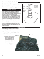
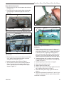
Vent Termination Below Grade
Install Snorkel Kit #7FSDVSKS when it is not possible
to meet the required vent termination clearances of 12”
(305 mm) above grade level. The snorkel kit will allow
installation depth of down to 7” (178 mm) below grade
level. The seven inches is measured from the center of
the horizontal vent pipe as it penetrates the wall. If the
venting system is installed below grade, a window
well must be installed with adequate and proper
drainage. (Fig. 29)
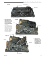
Vertical (Through the Roof)
Vent Assembly
Note that all vertically terminated installations must
include the restrictor plate included with the stove.
Refer to Page 9, Figure 8.
Make certain the vent system conforms to all other
requirements for vertical termination as specified on
Page 8.
This installation will require you to first determine the
roof pitch and use the appropriate vent components.
Refer to Pages 9 and 11, Figures 8 and 11.
1. Locate the final position of the stove, observing all
clearances for both the vent and the stove.
2. Plumb to the center of the inner (4”) flue collar from
the ceiling above, and mark that location.
3. Cut the opening:
CFM System: 9
³⁄₈” x 9³⁄₈” (240 x 240mm)
DuraVent System: 10” x 10” (254 x 254mm)
4. Plumb any additional opening through the roof or
other construction that may be needed. In all cases,
the opening must provide a minimum of 1” (25 mm)
clearance to the vent pipe.
5. Place the stove in its final position.
6. Install firestop(s) #7DVFS and Attic Insulation Shield
#7DVAIS as needed. (Fig. 31) If there is a room
above ceiling level, a firestop must be installed on
both the bottom and top sides of the ceiling joists.
If an attic is above ceiling level, an attic insulation
shield must be installed.
7. Install the appropriate roof support and flashing,
making certain that the upper flange of the flashing
base is below the shingles. (Fig. 32)
8. Install appropriate pipe sections until the vent run
reaches above the flashing. The enlarged ends of
the vent sections always face downward.
NOTE: Be sure to maintain side wall clearances and
vent run restrictions. Refer to Figures 5, 6, 7, and 8.
1. Establish the vent hole through the wall.
2. Remove soil to a depth of approximately 16”
(400mm) below the base of the snorkel. Install a
window well (not supplied). Refill the hole with 12”
(305mm) of coarse gravel and maintain a clearance
of at least 4” (102 mm) below the snorkel. (Fig. 33)
3. Install the vent system as described on Pages 15-18.
4. Be sure to make a watertight joint around the vent
pipe joint at the inside and outside wall joints.
5. Apply high temperature sealant around the inner
and outer snorkel collars. Join the pipes and fasten
the snorkel termination to the wall with the screws
provided.
6. Level the soil to maintain a 4” clearance below the
snorkel.
If the foundation is recessed, use extension brackets
(not supplied) to fasten the lower portion of the snor-
kel. Fasten the brackets to the wall first, and then
fasten to the snorkel with self-tapping #8 x 1/2” sheet
metal screws. Extend the vent pipes out as far as the
protruding wall face. (Fig. 30)

20
Stardance Direct Vent/Natural Vent Gas Heater
20012734
ST222
vent thru ceiling
12/99
#7DVAIS
Attic Insulation
Shield
#7DVFS
Firestop in
Upper Floor
#7DVFS
Firestop in
Ceiling
Use Four
8dNails
ST222
Fig. 31 Install firestops and attic insulation shield.
ST221
vent thru roof
12/99
Sealant
Storm Collar
Use three #5 sheet
metal screws at
each joint
Upper
edge of
flange
goes under
upper
shingles
Flashing
#7DVSKV
(A, B, or F)
RoofSupport
ST221
Fig. 32 Roof support and flashing.
Selkirk Direct-Temp Metalbestos Direct
Vent System
Installation Instructions
1. Determine whether the length of pipe fits the appli-
ance outlet by attempting to engage the parts. If the
parts engage smoothly, proceed to Step 2. If ob-
structions, interference or loose fit is noted, contact
the appliance manufacturer or Selkirk Metalbestos
with the dimensions of the appliance outlet.
2. Slide the length of pipe over the appliance outlet a
minimum of 1¹⁄₂” and screw to the appliance outlet
collar using a minimum of two (2) #8 x 1/4” sheet
metal screws.
Appliance Adapter (AAV)
The appliance adapter (AAV) adapts DIRECT-TEMP to
most direct vent appliances incorporating outlet collars
configured to receive most common 4” (ID) 6⁵⁄₈” (OD) or
5” (ID) by 8” (OD) “Twist Lock” Style, direct vent sys-
tems.
The adapter incorporates two (2) indentations on the
outer wall of the inlet end, which are designed to “Twist
Lock” into place upon attachment to the appliance
outlet. Align the adapter indentations with the entry
slots of the appliance outlet and slide together. Turn the
adapter clockwise approximately one-quarter turn to
lock in place. The outlet end of the adapter is standard
DIRECT-TEMP construction.
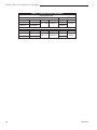
Framing Dimension Table 1
Model DT Ceiling Support (CS) Cathedral Ceiling Wall Thimble
Diameter Firestop (FS) Support CCS) (WT)
4” 8¹⁄₄” x 8¹⁄₄” 10⁵⁄₈” x 10⁵⁄₈” 8¹⁄₄” x 8¹⁄₄”
5” 10
¹⁄₈” x 10¹⁄₈” 14¹⁄₂” x 14¹⁄₂” 10¹⁄₈” x 10¹⁄₈”
9. Install the storm collar and seal around the joints.
(Fig. 32)
10. Add additional vent lengths to achieve the proper
overall height.
11. Apply cement to the inner and outer termination col-
lars and install the terminal cap.
Use of Sealant
It is not required to apply or use sealant on the inner
liner of DIRECT-TEMP. For outer wall joint sealing
considerations, follow appliance manufacturer recom-
mendations.
Joint Connection:
The pipe and elbows are assembled by inserting the
outlet (male) end of a length of pipe or elbow into the in-
let (female) end of an adjacent length of pipe or elbow.
Make sure the outlet end is fully seated within the inlet
end of the adjoining section and the gasket, located on
the inner liner of the inlet section is fully enclosed by the
inner liner of the outlet of the adjoining section. Push
in the Lock Tab such that it becomes seated within the
inward groove of the adjoining section. This locks the
joint in place. (Fig. 33)
Page is loading ...
Page is loading ...
Page is loading ...
Page is loading ...
Page is loading ...
Page is loading ...
Page is loading ...
Page is loading ...
Page is loading ...
Page is loading ...
Page is loading ...
Page is loading ...
Page is loading ...
Page is loading ...
Page is loading ...
Page is loading ...
Page is loading ...
Page is loading ...
Page is loading ...
Page is loading ...
Page is loading ...
Page is loading ...
Page is loading ...
Page is loading ...
Page is loading ...
Page is loading ...
Page is loading ...
Page is loading ...
Page is loading ...
Page is loading ...
Page is loading ...
Page is loading ...
-
 1
1
-
 2
2
-
 3
3
-
 4
4
-
 5
5
-
 6
6
-
 7
7
-
 8
8
-
 9
9
-
 10
10
-
 11
11
-
 12
12
-
 13
13
-
 14
14
-
 15
15
-
 16
16
-
 17
17
-
 18
18
-
 19
19
-
 20
20
-
 21
21
-
 22
22
-
 23
23
-
 24
24
-
 25
25
-
 26
26
-
 27
27
-
 28
28
-
 29
29
-
 30
30
-
 31
31
-
 32
32
-
 33
33
-
 34
34
-
 35
35
-
 36
36
-
 37
37
-
 38
38
-
 39
39
-
 40
40
-
 41
41
-
 42
42
-
 43
43
-
 44
44
-
 45
45
-
 46
46
-
 47
47
-
 48
48
-
 49
49
-
 50
50
-
 51
51
-
 52
52


Vermont Casting Gas Heater SDDVTCB, SDDVTEB, SDDVTMB, SDDVTBS, SDDVTCH, SDDVTVG, SDDVTBD,SDDVTCCB, SDDVTCEB, SDDVTCMB, SDDVTCBS, SDDVTCCH, SDDVTCVG, SDDVTCBD User manual
- Category
- Stoves
- Type
- User manual
Ask a question and I''ll find the answer in the document
Finding information in a document is now easier with AI
Related papers
-
Vermont Casting ST208 User manual
-
Vermont Castings SDDVRBS User manual
-
-
Vermont Castings VCBV10TN User manual
-
-
Vermont Casting DVHVAC36 User manual
-
-
-
Vermont Casting 3340 User manual
-
Other documents
-
Procom PF09B Installation guide
-
 Drolet Nova 820 User manual
-
Akura ALEDVD31511E User guide
-
-
HQ W9-AD-34-12B Datasheet
-
-
TRIANGLE TUBE Horizontal Vent Termination Kit Operating instructions
-
-
-
Rheem XG40T06PN36U1 Installation guide
