ESAB Migmaster 280 Pro User manual
- Category
- Welding System
- Type
- User manual

0349 300 093 Valid for serial no. 016, 018--xxx--xxxx100624
Migmasterr 280 Pro
S
e
r
v
i
c
e
m
a
n
u
a
l

-- 2 --
TOCe
READ THIS FIRST 3. . . . . . . . . . . . . . . . . . . . . . . . . . . . . . . . . . . . . . . . . . . . . . . . . . . . . . . . . . . . . . . . .
INTRODUCTION 3. . . . . . . . . . . . . . . . . . . . . . . . . . . . . . . . . . . . . . . . . . . . . . . . . . . . . . . . . . . . . . . . . . .
TECHNICAL DATA 4. . . . . . . . . . . . . . . . . . . . . . . . . . . . . . . . . . . . . . . . . . . . . . . . . . . . . . . . . . . . . . . . .
WIRING DIAGRAM 5. . . . . . . . . . . . . . . . . . . . . . . . . . . . . . . . . . . . . . . . . . . . . . . . . . . . . . . . . . . . . . . . .
Component description 5. . . . . . . . . . . . . . . . . . . . . . . . . . . . . . . . . . . . . . . . . . . . . . . . . . . . . . . . . .
Migmasterr 280 Pro, 230/208V 6. . . . . . . . . . . . . . . . . . . . . . . . . . . . . . . . . . . . . . . . . . . . . . . . . . . .
Migmasterr 280 Pro, 230/208V 7. . . . . . . . . . . . . . . . . . . . . . . . . . . . . . . . . . . . . . . . . . . . . . . . . . . .
Migmasterr 280 Pro, 208/230/460/575V 8. . . . . . . . . . . . . . . . . . . . . . . . . . . . . . . . . . . . . . . . . . . .
DESCRIPTION OF OPERATION 10. . . . . . . . . . . . . . . . . . . . . . . . . . . . . . . . . . . . . . . . . . . . . . . . . . . . .
AP1 Control board 10. . . . . . . . . . . . . . . . . . . . . . . . . . . . . . . . . . . . . . . . . . . . . . . . . . . . . . . . . . . . . .
AP1:1 Power supply 10. . . . . . . . . . . . . . . . . . . . . . . . . . . . . . . . . . . . . . . . . . . . . . . . . . . . . . . . . . . . . .
AP1:2 Start / Stop 10. . . . . . . . . . . . . . . . . . . . . . . . . . . . . . . . . . . . . . . . . . . . . . . . . . . . . . . . . . . . . . . .
AP1:3 Spot welding 11. . . . . . . . . . . . . . . . . . . . . . . . . . . . . . . . . . . . . . . . . . . . . . . . . . . . . . . . . . . . . . .
AP1:4 Wire feed speed, creep start 11. . . . . . . . . . . . . . . . . . . . . . . . . . . . . . . . . . . . . . . . . . . . . . . . .
AP1:5 Motor control 12. . . . . . . . . . . . . . . . . . . . . . . . . . . . . . . . . . . . . . . . . . . . . . . . . . . . . . . . . . . . . .
AP1:6 Burnback time, contactor, gas valve 13. . . . . . . . . . . . . . . . . . . . . . . . . . . . . . . . . . . . . . . . . . .
AP1:7 Thermal overload cutout 13. . . . . . . . . . . . . . . . . . . . . . . . . . . . . . . . . . . . . . . . . . . . . . . . . . . . .
AP1 -- Migmasterr 280 Pro component positions 14. . . . . . . . . . . . . . . . . . . . . . . . . . . . . . . . . . . . . .
AR Control board 15. . . . . . . . . . . . . . . . . . . . . . . . . . . . . . . . . . . . . . . . . . . . . . . . . . . . . . . . . . . . . . .
AR component positions 15. . . . . . . . . . . . . . . . . . . . . . . . . . . . . . . . . . . . . . . . . . . . . . . . . . . . . . . . . . .
AR diagram 15. . . . . . . . . . . . . . . . . . . . . . . . . . . . . . . . . . . . . . . . . . . . . . . . . . . . . . . . . . . . . . . . . . . . . .
AP2 Digital instrument 16. . . . . . . . . . . . . . . . . . . . . . . . . . . . . . . . . . . . . . . . . . . . . . . . . . . . . . . . . . .
AP2:1 Calibration and voltage correction 16. . . . . . . . . . . . . . . . . . . . . . . . . . . . . . . . . . . . . . . . . . . . .
SERVICE INSTRUCTIONS 17. . . . . . . . . . . . . . . . . . . . . . . . . . . . . . . . . . . . . . . . . . . . . . . . . . . . . . . . . .
What is ESD? 17. . . . . . . . . . . . . . . . . . . . . . . . . . . . . . . . . . . . . . . . . . . . . . . . . . . . . . . . . . . . . . . . . . .
Thermal switch (thermostat) replacement procedure 17. . . . . . . . . . . . . . . . . . . . . . . . . . . . . . .
INSTRUCTIONS 18. . . . . . . . . . . . . . . . . . . . . . . . . . . . . . . . . . . . . . . . . . . . . . . . . . . . . . . . . . . . . . . . . . .
SAFETY 18. . . . . . . . . . . . . . . . . . . . . . . . . . . . . . . . . . . . . . . . . . . . . . . . . . . . . . . . . . . . . . . . . . . . . . . .
INSTALLATION 19. . . . . . . . . . . . . . . . . . . . . . . . . . . . . . . . . . . . . . . . . . . . . . . . . . . . . . . . . . . . . . . . . . . .
Placing 19. . . . . . . . . . . . . . . . . . . . . . . . . . . . . . . . . . . . . . . . . . . . . . . . . . . . . . . . . . . . . . . . . . . . . . . . .
Electrical installation 19. . . . . . . . . . . . . . . . . . . . . . . . . . . . . . . . . . . . . . . . . . . . . . . . . . . . . . . . . . . .
Welding voltage polarity 20. . . . . . . . . . . . . . . . . . . . . . . . . . . . . . . . . . . . . . . . . . . . . . . . . . . . . . . . .
Mains power supply 20. . . . . . . . . . . . . . . . . . . . . . . . . . . . . . . . . . . . . . . . . . . . . . . . . . . . . . . . . . . . .
OPERATION 21. . . . . . . . . . . . . . . . . . . . . . . . . . . . . . . . . . . . . . . . . . . . . . . . . . . . . . . . . . . . . . . . . . . . . . .
Connection and control devices 21. . . . . . . . . . . . . . . . . . . . . . . . . . . . . . . . . . . . . . . . . . . . . . . . . .
Switching--on and overheating protection 22. . . . . . . . . . . . . . . . . . . . . . . . . . . . . . . . . . . . . . . . .
Operation 22. . . . . . . . . . . . . . . . . . . . . . . . . . . . . . . . . . . . . . . . . . . . . . . . . . . . . . . . . . . . . . . . . . . . . . .
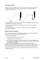
Replacing and inserting wire 22. . . . . . . . . . . . . . . . . . . . . . . . . . . . . . . . . . . . . . . . . . . . . . . . . . . . .
Wire feed pressure 23. . . . . . . . . . . . . . . . . . . . . . . . . . . . . . . . . . . . . . . . . . . . . . . . . . . . . . . . . . . . . .
MIG process set--up guide 23. . . . . . . . . . . . . . . . . . . . . . . . . . . . . . . . . . . . . . . . . . . . . . . . . . . . . . .
MAINTENANCE 25. . . . . . . . . . . . . . . . . . . . . . . . . . . . . . . . . . . . . . . . . . . . . . . . . . . . . . . . . . . . . . . . . . . .
Inspection and cleaning 25. . . . . . . . . . . . . . . . . . . . . . . . . . . . . . . . . . . . . . . . . . . . . . . . . . . . . . . . .
FAULT TRACING 26. . . . . . . . . . . . . . . . . . . . . . . . . . . . . . . . . . . . . . . . . . . . . . . . . . . . . . . . . . . . . . . . . .
ORDERING OF SPARE PARTS 26. . . . . . . . . . . . . . . . . . . . . . . . . . . . . . . . . . . . . . . . . . . . . . . . . . . . . .
NOTES 27. . . . . . . . . . . . . . . . . . . . . . . . . . . . . . . . . . . . . . . . . . . . . . . . . . . . . . . . . . . . . . . . . . . . . . . . . . .

Edition 100624
-- 3 --
1sM280P
READ THIS FIRST
Maintenance and repair work should be performed by an experienced person, and
electrical work only by a trained electrician. Use only recommended replacement parts.
This service manual is intended for use by technicians with electrical/electronic training for
help in connection with fault--tracing and repair.
Use the wiring diagram as a form of index for the description of operation. The circuit
board is divided into numbered blocks, which are described individually in more detail in
the description of operation. All component names in the wiring diagram are listed in the
component description.
This manual contains details of all design changes that have been made up to and
including June 2010.
The Migmasterr
rr
r 280Pro is designed and tested in accordance with international and
European standard IEC/EN 60974--1 and EN 60974--10.
On completion of service or repair work, it is the responsibility of the person(s) etc.
performing the work to ensure that the product does not depart from the requirements
of the above standard.
INTRODUCTION
Migmasterr
rr
r 280 Pro is step controlled power source in a compact design, intended
for welding with solid steel, stainless steel or aluminium wire as well as flux--cored
wire with or without shielding gas.
The machine is equipped with facilities for connection of the MIG ”spool--on” gun
torch (type: MT--250SG, ST23A+Adapter KIT ST--23A).
Do not dispose of electrical equipment together with normal waste!
In observance of European Directive 2002/96/EC on Waste Electrical and Electronic
Equipment and its implementation in accordance with national law, electrical equipment
that has reached the end of its life must be collected separately and returned to an
environmentally compatible recycling facility. As the owner of the equipment, you should
get information on approved collection systems from our local representative.
By applying this European Directive you will improve the environment and human health!

Edition 100624
-- 4 --
1sM280P
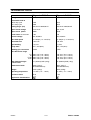
TECHNICAL DATA
Migmasterr
rr
r 280 Pro Migmasterr
rr
r 280 Pro
Voltage 208V/230V, 1∼ 50/60Hz 208/230/460/575V, 1∼ 50/60Hz
Permissible load at
100% duty cycle 194A 194A
60 % duty cycle 250A 250A
Setting range (DC) 40A/16.0V--300A/29.0V 40A/16.0V--300A/29.0V
Open circuit voltage 16,8--57,0V 16,8--57,0V
Open circuit power 450W 450W
Power factor at max load 0.84 0.84
Control voltage 42V, 50/60Hz 42V, 50/60Hz
Wire feed speed 55--750ipm (1.4--19m/min) 55--750ipm (1.4--19m/min)
Burnback time 0.03--0.5s 0.03--0.5s
Spot welding 0.5--3.5s 0.5--3.5s
Creep start OFF / ON (85%) OFF / ON (85%)
Welding gun connection EURO EURO
Wire dimension range
Fe
Al
FCW
CuSi
.030--.047” (0.8--1.2mm)
.040--.047” (1.0--1.2mm)
.030--.047” (0.8--1.2mm)
.030--.039” (0.8--1.0mm)
.030--.047” (0.8--1.2mm)
.040--.047” (1.0--1.2mm)
.030--.047” (0.8--1.2mm)
.030--.039” (0.8--1.0mm)
Max diameter/weight
of wire bobin
12” (300mm)/33lb (15kg) 12” (300mm)/33lb (15kg)
Dimensions lxwxh 32x21.7x34.3”
(812x552x870mm)
32x21.7x34.3”
(812x552x870mm)
Weight 341lb (155kg) 350lb (159kg)
Operating temperature 14÷104F (--10 ÷ +40
o
C) 14÷104F (--10 ÷ +40
o
C)
Enclosure class IP 23 IP 23
Application classification

Edition 100624
-- 5 --
1sM280P
WIRING DIAGRAM
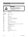
Component description
WARNING !
STATIC ELECTRICITY can damage circuit
boards and electronic components.
S
SS
S Observe precautions for handling electrostatic
sensitive devices.
S
SS
S Use proper static--proof bags and boxes.
ESD
AP1
Circuit board
AP2
Digital instrument
C1, C2, CVS
Capacitor 0,1uF/250V
EV1, EV2
Fan
KM1
Contactor 42V, 50--60Hz
L1
Inductor
M1
Feed unit motor
QF1
Switch, ON/OFF
QF2
Rotary switch, fine welding voltage selector
QF3
Rotary switch, coarse welding voltage selector
RO
Resistor 15Ω/20W
RVS
Resistor
RP1
Potentiometer, wire feed speed
RP3
Potentiometer with switch, spot welding
RI
Shunt
ST1
Thermal oveload cutout, operates at 130
o
C. The cutout is mounted at the
cooling fins of the diode bridge.
TC1
Control transformer
TC3
Transformer for digital instrument
TM1
Main transformer
V1
Diode bridge
VH
LED orange
VL
LED white (or green)
XTM
Reconnection block (main transformer)
YV1
Gas valve

Edition 100624
-- 6 --
1sM280P
Migmaster
r
rr
r
280 Pro, 230/208V

Edition 100624
-- 7 --
1sM280P
Migmaster
r
rr
r
280 Pro, 230/208V

Edition 100624
-- 8 --
1sM280P
Migmasterr
rr
r 280 Pro, 208/230/460/575V

Edition 100624
-- 9 --
1sM280P
Migmasterr
rr
r 280 Pro, 208/230/460/575V

Edition 100624
-- 10 --
1sM280P
DESCRIPTION OF OPERATION
AP1 Control board
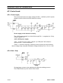
AP1:1 Power supply
The circuit board uses one supply voltage: 27VAC -- rectified by V18 for power
supply to the wire feed motor and electronic circuitry.
Power supply to the electronic circuitry
The +35VS power supply from diode V9 through R31 -- is regulated to 15V by
voltage regulator A2.
+35V/+35VS power supply
+35V -- is used for motor control, relay K1 (on PCB) and ”ON” indication
(optional, LED -- on the front panel)
+35VS -- is used for powering of auxiliary control circuits (see next sections).
Above voltages may vary (with load/mains voltage deviation) from --15% to +10%.
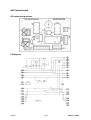
AP1:2 Start / Stop
Closing trigger contact on the welding torch starts the welding process.
The PCB provides only two--stroke control mode.

Edition 100624
-- 11 --
1sM280P
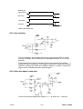
T 1
0
0
0
0
1
1
1
1
Gas valve
W
e
l
d
i
n
g
g
u
n
trigger switch
Wire feed
Contactor
T1 = Burn--back time
T 1
Start-- stop sequence.
AP1:3 Spot welding
The spot welding is active when the switch in potentiometer RP2 is closed
(turning clockwise). Spot welding time is adjustable between ca 0,5 and 3,5
seconds.
If the welding torch trigger is released during a spot welding, the welding
sequences will be interrupted. If the trigger is pressed for longer than the spot
weld time, welding stops after spot weld time elapses. In order to restart, the
trigger must be released and then pressed again.
AP1:4 Wire feed speed, creep start
The wire feed speed adjustment range is 1,4 -- 19 m/min (55 -- 750 ipm).

Edition 100624
-- 12 --
1sM280P
The +5,1V reference voltage (±1%) is derived from the IC -- A4 (PWM
generator).
The creep start function enables the start of welding at reduced wire speed
and after ca 0,5 sec speed increases automatically to the value set with RP1.
Initial wire speed -- ”creep speed” (85% or 100% of the preset work speed) is
selected with the switch S1 on the PCB -- accessible from the wire drive
compartment.
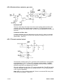
AP1:5 Motor control
The motor is powered by the smoothed +35 V supply. Pulse width modulation
of the transistor V11 controls the motor voltage. The pulse frequency is about
16 kHz, and maximum conduction time of the pulses is about 95% of the pulse
cycle time. During the Off period of the pulse cycle, the motor current
freewheels through diode V12.
At 24V motor supply voltage, the wire feed roller speed is 160 rpm ±5%. At a
roller speed of 200rpm, the wire feed speed is 19 m/min ±5%.
Speed control
The gate pulses to transistor V11 are generated by a PWM circuit (IC A4),
which compares speed reference with signal proportional to the motor voltage.
Current limit
The current limit is set at ca 6,0 A. The motor current is measured by resistor
R42 which produces a voltage drop proportional to the current (1A = 100mV).
The current limit restricts the conduction time of the gate pulses to transistor
V11.
I x R Compensation
The network R38, R44, R45 allows to compensate the voltage drop on the
motor armature resistance in order to improve wire transportation (especially at
low speed settings).

Edition 100624
-- 13 --
1sM280P
AP1:6 Burnback time, contactor, gas valve
Burnback time
The burn--back time is the time from when motor braking starts until the main
contactor opens. When welding stops, capacitor C7 is discharged through
potentiometer R27 and resistor R28. The time can be adjusted from 0,03 to 0,5
seconds.
Contactor and Gas valve
Contactor and gas valve are switched--on by the relay K1, which is controled
by transistor V3. Resistors R18 and R19 reduce the voltage on the coil of K1
(rated value -- 24V DC).
AP1:7 Thermal overload cutout
The thermal overload cutout ST1 is mounted on the transformer, and operates
at a temperature of 130 °C. When ST1 operates (contact opens), ”ALARM”
signal goes high (11,5 -- 15V), the output signals from the PCB are disabled
and the orange LED VH indicates the overload.
When the equipment cools down, ST1 resets automatically. The LED VL (white
or green) indicates energising of the welding machine, it is ON independently
of the overload signalling.
Note: LED VL is only installed optionally if there is no external ON--lamp (refer
to the Electrical diagram -- lamp LF1).

Edition 100624
-- 14 --
1sM280P
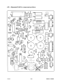
AP1 -- Migmasterr
rr
r 280 Pro component positions

Edition 100624
-- 15 --
1sM280P
AR Control board
AR component positions
AR diagram

Edition 100624
-- 16 --
1sM280P
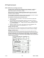
AP2 Digital instrument
AP2:1 Calibration and voltage correction
The meter has a possibility of the voltage and current calibration, as well as a
possibility of the current--dependant voltage correction, to show a voltage
approximately equal to the actual arc voltage.
Since all meters are factory calibrated it is recommended to carry out a second
calibration only if it’s needed. In most applications a zero voltage correction (no
correction) is factory adjusted.
For the calibration an accurate reference meter and a resistance load are required.
The resistance load should force at least 100A current flow.
For calibration following actions should be done:
1 Switch the machine on and load it. The meter should indicate voltage and
current presence.
2 Press simultaneously both pushbuttons placed on the meter PC board. In
sequence, symbols of the calibration modes appear: ”U” -- voltage calibration,
”I” -- current calibration, ”dU” -- voltage correction. Release the buttons as the
required mode appears.
3 Adjust the voltage or the current value equal to the value displayed on the
reference meter by means of the pushbuttons: S1 ”+”, S2 ”--”.
Voltage calibration mode
The reference meter should be connected to the same potentials as a calibrated
meter. Exclusively in this mode a voltage without correction is shown on display.
Voltage correction mode
The reference meter should be connected to the end of mass cable and to the
torch current tip, which are connected to the external load. In this mode, as well as
during the regular work, the meter shows a voltage taking in account voltage drops
on cables and welding torch. An adjustment of the voltage correction should be
carried out only in assumption of the proper voltage calibration and in the presence
of load current above 100A.

Edition 100624
-- 17 --
1sM280P
SERVICE INSTRUCTIONS
What is ESD?
A sudden transfer or discharge of static electricity from one object to another. ESD stands for
Electrostatic Discharge.
How does ESD damage occur?
ESD can cause damage to sensitive electrical components, but is not dangerous to people.
ESD damage occurs when an ungrounded person or object with a static charge comes into
contact with a component or assembly that is grounded. A rapid discharge can occur,
causing damage. This damage can take the form of immediate failure, but it is more likely
that system performance will be affected and the component will fail prematurely.
How do we prevent ESD damage?
ESD damage can be prevented by awareness. If static electricity is prevented from building
up on you or on anything at your work station, then there cannot be any static discharges.
Nonconductive materials (e.g. fabrics), or insulators (e.g. plastics) generate and hold static
charge, so you should not bring unnecessary nonconductive items into the work area.
It is obviously difficult to avoid all such items, so various means are used to drain off any
static discharge from persons to prevent the risk of ESD damage. This is done by simple
devices: wrist straps, connected to ground, and conductive shoes.
Work surfaces, carts and containers must be conductive and grounded, use only antistatic
packaging materials. Overall, handling of ESD--sensitive devices should be minimized to
prevent damage.
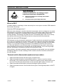
WARNING !
STATIC ELECTRICITY can damage circuit
boards and electronic components.
S
SS
S Observe precautions for handling electrostatic
sensitive devices.
S
SS
S Use proper static--proof bags and boxes.
ESD
Thermal switch (thermostat) replacement procedure
1. Spare thermostat must be the same type as replaced one.
2. Spare thermostat should be mounted within radius of 10mm or less from broken
thermostat. If it’s possible and safe for transformer winding, broken thermostat may be
removed. Then the spare thermostat is to be mounted right in place of broken one.
3. Spare thermostat should adjoin protected winding as tight as possible.
4. Spare thermostat must be secured with silicone glue of working temperature of 200
o
C
or higher.

Edition 100624
-- 18 --
2sM280P
INSTRUCTIONS
This chapter is an extract from the instructions for Migmasterr 280 Pro.
SAFETY
Users of ESAB welding equipment have the ultimate responsibility for ensuring that anyone who
works on or near the equipment observes all the relevant safety precautions. Safety precautions
must meet the requirements that apply to this type of welding equipment. The following recommen-
dations should be observed in addition to the standard regulations that apply to the workplace.
All work must be carried out by trained personnel well--acquainted with the operation of the welding
equipment. Incorrect operation of the equipment may lead to hazardous situations which can result
in injury to the operator and damage to the equipment.
1. Anyone who uses the welding equipment must be familiar with:
S its operation
S location of emergency stops
S its function
S relevant safety precautions
S welding
2. The operator must ensure that:
S no unauthorised person is stationed within the working area of the equipment when it is
started up.
S no--one is unprotected when the arc is struck
3. The workplace must:
S be suitable for the purpose
S be free from draughts
4. Personal safety equipment
S Always wear recommended personal safety equipment, such as safety glasses, flame--proof
clothing, safety gloves.
S Do not wear loose--fitting items, such as scarves, bracelets, rings, etc., which could become
trapped or cause burns.
5. General precautions
S Make sure the return cable is connected securely.
S Work on high voltage equipment may only be carried out by a qualified electrician.
S Appropriate fire extinquishing equipment must be clearly marked and close at hand.
S Lubrication and maintenance must not be carried out on the equipment during operation.
WARNING!
Read and understand the instruction manual
before installing or operating.

Edition 100624
-- 19 --
2sM280P
INSTALLATION
The installation must be executed by a professional.
WARNING!
This product is intended for industrial use. In a domestic environment this product may cause radio
interference. It is the user’s responsibility to take adequate precautions.
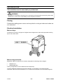
Placing
Position the welding power source such way that its cooling air inlets and outlets are
not obstructed.
Electrical installation
Mains voltage
All machines are factory configured for highest rated voltage and are fitted with appropriate marking
tape on the mains cable.
Mains voltage selection
Migmasterr 280 Pro is delivered in versions configurable for following mains voltages:
S 208/230V and
S 208/230/460/575V
Factory configuration is set for 230V and 575V respectively.
In order to adapt the machines for the other voltages, it is necessary to reconnect the main
transformer TM1 and control transformer TC1 as shown and described on the schematic diagrams.

Edition 100624
-- 20 --
2sM280P
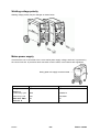
Welding voltage polarity
Welding voltage polarity may be changed as shown below.
Mains power supply
Check that the unit is connected to the correct mains power supply voltage, and that it is protected by
the correct fuse size. A protective earth connection must be made, in accordance with regulations.
Rating plate with supply connection data
Migmasterr
rr
r 280 Pro Migmasterr
rr
r 280 Pro
Voltage 208/230V, 1∼ 50/60Hz 208/230/460/575V, 1∼ 50/60Hz
Current A
at 100% duty cycle 40/36 40/36/24/15
at 60% duty cycle 57/51 57/51/30/21
Cable area AWG 3x6 3x6
Fuse slow A 50 50
Page is loading ...
Page is loading ...
Page is loading ...
Page is loading ...
Page is loading ...
Page is loading ...
Page is loading ...
Page is loading ...
Page is loading ...
-
 1
1
-
 2
2
-
 3
3
-
 4
4
-
 5
5
-
 6
6
-
 7
7
-
 8
8
-
 9
9
-
 10
10
-
 11
11
-
 12
12
-
 13
13
-
 14
14
-
 15
15
-
 16
16
-
 17
17
-
 18
18
-
 19
19
-
 20
20
-
 21
21
-
 22
22
-
 23
23
-
 24
24
-
 25
25
-
 26
26
-
 27
27
-
 28
28
-
 29
29


ESAB Migmaster 280 Pro User manual
- Category
- Welding System
- Type
- User manual
Ask a question and I''ll find the answer in the document
Finding information in a document is now easier with AI
Related papers
-
ESAB Migmaster® 280 Pro User manual
-
-
-
-
-
ESAB Feed 30, Feed 30w User manual
-
-
-
-

