Page is loading ...

ELECTROSTATIC DISCHARGE
SIMULATOR
Model 930D & 930D FTS
Operating Manual
5/11

1
IMPORTANT
SAFETY INSTRUCTIONS
(Equipment containing HV)
The equipment described in this Manual is designed and manufactured to operate within
defined design limits. Any misuse may result in electric shock or fire. To prevent the
equipment from being damaged, the following rules should be observed for installation,
use and maintenance. Read the following safety instructions before operating the
instrument. Retain these instructions in a safe place for future reference.
POWER
POWER CORD: Use only the power cord specified for this equipment and certified for
the country of use. If the power (mains) plug is replaced, follow the wiring connections
specified for the country of use. When installing or removing the power plug hold the
plug, not the cord.
The power cord provided is equipped with a 3-prong grounded plug (a plug with a
third grounding pin). This is both a safety feature to avoid electrical shock and a
requirement for correct equipment operation. If the outlet to be used does not
accommodate the 3-prong plug, either change the outlet or use a grounding adapter.
FUSES: Replace fuses only with those having the required current rating, voltage and
specified type such as normal blow, time delay, etc. DO NOT use makeshift fuses or
short the fuse holder. This could cause a shock or fire hazard or severely damage the
instrument.
POWER LINE VOLTAGE (MAINS): If the line (mains) voltage is changed or isolated
by an autotransformer the common terminal must be connected to the ground (earth)
terminal of the power source.
OPERATION
CAUTION
Equipment designed to simulate a high voltage electrostatic discharge such as the
Series 900 ESD Simulators and the Model 4046 Static Decay Meter utilize voltages up
to 30kV. The basic nature of an ESD event will result in electromagnetic radiation in
addition to the high level, short duration current pulse. Therefore, personnel with a
heart pacemaker must not operate the instrument or be in the vicinity while it is
being used.
DO NOT OPERATE WITH COVERS OR PANELS REMOVED. Voltages inside the
equipment consist of line (mains) that can be anywhere from 100-240VAC, 50/60Hz
and in some equipment, voltages as high a 30kV. In addition, equipment may contain
capacitors up to 0.035 μF charged to 30kV and capacitors up to 0.5 μF charged up
6kV. Capacitors can retain a charge even if the equipment is turned off.
DO NOT OPERATE WITH SUSPECTED EQUIPMENT FAILURES. If any odor or
smoke becomes apparent turn off the equipment and unplug it immediately. Failure to
do so may result in electrical shock, fire or permanent damage to the equipment.
Contact the factory for further instructions.

2
DO NOT OPERATE IN WET/DAMP CONDITIONS: If water or other liquid penetrates
the equipment, unplug the power cord and contact the factory for further instructions.
Continuous use in this case may result in electrical shock, fire or permanent damage to
the equipment.
DO NOT OPERATE IN HIGH HUMIDITY: Operating the equipment in high humidity
conditions will cause deteriation in performance, system failure, or present a shock or
fire hazard. Contact the factory for further instructions.
DO NOT OPERATE IN AREAS WITH HEAVY DUST: Operating the equipment in high
dust conditions will cause deteriation in performance, system failure, or present a
shock or fire hazard. Contact the factory for further instructions.
DO NOT OPERATE IN AN EXPLOSIVE ATMOSPHERE: Operating the equipment in
the presence of flammable gases or fumes constitutes a definite safety hazard. For
equipment designed to operate in such environments the proper safety devices must
be used such as dry air or inert gas purge, intrinsic safe barriers and/or explosion-proof
enclosures.
DONOT USE IN ANY MANNER NOT SPECIFIED OR APPROVED BY THE
MANUFACTURER: Unapproved use may result in damage to the equipment or
present an electrical shock or fire hazard.
MAINTENANCE and SERVICE
CLEANING: Keep surfaces clean and free from dust or other contaminants. Such
contaminants can have an adverse affect on system performance or result in
electrical shock or fire. To clean use a damp cloth. Let dry before use. Do not use
detergent, alcohol or antistatic cleaner as these products may have an adverse affect
on system performance.
SERVICE: Do not attempt to repair or service the instrument yourself unless instructed
by the factory to do so. Opening or removing the covers may expose you to high
voltages, charged capacitors, electric shock and other hazards. If service or
repair is required, contact the factory.

3
1.0 INTRODUCTION
The Model 930D Electrostatic Discharge Simulator is an instrument that is designed
to simulate the discharge produced by an electrostatically charged human body
when it is brought close to an object that is at a lower potential. By use of additional
R-C modules and probes, the Discharge Simulator can also simulate the effects of
other types of discharges such as a person holding a metal object as defined in EN
61000-4-2 (formerly IEC 1000-4-2/801-2 and IEC 801-2). In addition, with
appropriate R/C networks and output cables the Simulator can test to MIL STD
1512, 1576, 331C, MIL-DTL 23659D etc.
Static charges are generally created when dissimilar objects are brought into
contact with each other and then separated. When this situation occurs, electrons
are transferred from one object to the other. If these objects are electrostatically
conductive (i.e., have surface resistivities of less than 10
12
ohms per square) and
are both connected to a third conductive body or to each other, the built-up static
charge will flow from one body to the other in a short time. The resulting net charge
build-up will be zero. If, on the other hand, these same electrostatically charged
objects are separated by an insulator, the charge build-up may not be neutralized
and each body may retain its charge for a long time, particularly in a low humidity
environment.
The charging of objects due to relative motion is known as the Triboelectric Effect
and can produce voltages from a few Volts to tens of thousands of Volts. The
charge build-up depends on many factors including the amount and rate of motion,
the composition of the materials involved, the secondary surfaces involved (floor,
table top, air, etc.), the relative humidity level of the air surrounding the charged
bodies and surface coatings used on any of the surfaces (if any). When a highly
charged body is brought near an electrostatically neutral body or one that has an
opposite charge, a rapid discharge can occur. In many cases, this discharge is
nothing more than an annoyance; however, in some cases the discharge can result
in the disruption of an industrial process, the loss of valuable data, damage to
sensitive components or an explosion that can result in injury and/or the loss of life.
One of the most common types of electrostatic build-ups occurs with the flow of
people and material over nonconductive surfaces. Humidity conditions usually
determine how static dissipative a surface is. The lower the humidity, the longer the
static charge dissipation of a nonconductive material. A person walking across a
carpet or tile floor on a dry day is capable of generating an electrostatic body
charge in excess of 15,000 Volts. When the person comes in contact with an
electrostatically conductive object, he immediately discharges the accumulated
charge on his body. If the charge build-up is about 3,000 Volts, the person will feel
only a slight shock. However, if the charge build-up is much larger, a visible spark
discharge will occur that can cause not only discomfort to the person but possible
damage to the item contacted.
In the past, electrostatic discharges were generally of less concern than they are
today. With the introduction of more and more synthetic materials, many of which
are easily charged, and the development of complex electronic equipment that may
contain electrostatic discharge sensitive components, the effects of electrostatic
discharge have become a major concern. Many electronic components can be
damaged or destroyed when subjected to electrostatic discharges of less than 100

4
Volts. Discharges of tens of thousands of Volts can have devastating effects on
such things as electronic communication systems, medical electronic systems,
computers and home entertainment systems.
It is virtually impossible to control the environment in which most of today’s high
technology equipment is used. The burden falls on the manufacturer to design and
build equipment that can function without disruption or failure when subjected to
commonly occurring electrostatic discharges. The Model 930D Electrostatic
Discharge Simulator can be an invaluable aid in helping to develop and test
equipment so that it can function reliably in today’s military, industrial and consumer
environments.
While the Model 930D is primarily designed for testing systems it can also be
adapted to test components meeting waveform requirements in accordance with Mil
Std 883, Method 3015, ESD STM5.1 (HBM) from 500 to 26,000 V and 5.2 (MM)
from 100 to >800 V plus the capability to perform charged device model tests
(CDM) up to 26 kV. Waveform verification is performed using an IEC test target
(ETS Model 949).
2.0 EQUIPMENT DESCRIPTION
2.1 General
The Model 930D Electrostatic Discharge Simulator can produce discharge
pulses from <±100 Volts to >±26kV. Energy is stored in a plug-in self-
contained capacitor bank during the charging period. A discharge pulse is
produced when a high voltage gas filled relay disconnects the charged
capacitor bank from its charging source and reconnects it to the output
electrode of the Discharge Simulator Gun in the RELAY mode. In the AIR
DISCHG (DISCHARGE) Mode the relay remains closed as long as the
trigger or DISCHARGE button is depressed. The discharge occurs when the
operator brings the ESD gun up to the System Under Test (SUT). The
energy storage capacitor bank and discharge resistor are contained in either
individual plug-in modules or in a common module, depending on the R/C
model specified. Capacitor and resistor modules are selected by the user
and must be ordered at the time of purchase to configure the initial system.
Standard and custom modules are available with capacitor values ranging
from 60pf to 500pf and resistor values ranging from 100 to 10,000 ohms.
Contact ETS for capacitor modules above 500pf. Figure 2.1a and b are
typical HBM and IEC waveforms.
The following resistor and capacitor modules are some of the common
networks currently in use along with the corresponding discharge
waveforms:
R ohms C pF Mode Waveform Application
1,500 100 Relay A Discharge from Human Body
150 150 Air A EN 61000-4-2
330 150 Relay B EN 61000-4-2
2,000 300 Relay B Automotive Industry
10,000 60 Relay A Telephone Industry
0 500 Relay A Explosives
5,000 500 Relay A Explosives

5
a b
Figure 2.1-1: Typical EDS Waveforms
All “A” waveforms are produced when the capacitor only is contained within
the CAPACITOR module and the resistor is contained in the RESISTOR
assembly that is plugged into the nose of the ESD Simulator. All “B”
waveforms are produced when both the capacitor and resistor are contained
in the CAPACITOR module and a “0” Ohm resistor is plugged into the
nose. This configuration is generally referred to as the IEC style waveform.
All waveforms are obtained using an IEC specified test target (ETS Model
949).
The principle of operation of the discharge simulator is illustrated in Figure
2.1-1.
Figure 2.1-1 Simplified Block Diagram
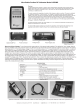
The Electrostatic Discharge Simulator, shown in Figure 2.1-2, is contained in
two (2) parts: a Control Unit and a Gun Assembly. The two units are
interconnected by a detachable 15-pin sub D cable. The system shown in
Figure 2.1-3 is the Model 930D FTS. The FTS (Firing Test Set) is identical to
the Model 930D except the Gun Assembly is modified for mounting in a fixed
position, instead of being hand held that provide for air, continuous or
automatic discharge pulse generation. In the AIR DISCHG mode the gun tip
is charged and then brought up to the SUT until a discharge occurs. In the
RELAY mode, the discharge to the SUT is produced by the relay closure. In
FREE RUN, the system will continue to produce discharge pulses as long as
the OPERATING MODE switch is in the AUTO Trigger position. The dwell

6
time or charging period between discharge pulses is adjustable by the user
from 1/3 second to about 20 seconds.
In Auto Count, the user selects the number of discharge pulses desired (1 to
9) and then either depresses the Gun Trigger pushbutton or activates the
AUTO Trigger Switch. The Discharge Simulator will then produce the
selected number of pulses at the selected time interval between pulses. A
single digit numeric readout displays the number of pulses from 1-9
produced. When the Trigger Switch is released or the AUTO Trigger is
turned off, the system counter resets to zero and the production of HV output
pulses stops. The discharge pulse sequence is repeated each time either the
MANUAL or AUTO Trigger Switch is activated.
Figure 2.1-2 Model 930D Electrostatic Discharge Simulator
Figure 2.1-3 Model 930D FTS

7
The control unit has a duplicate set of controls for remote gun operation. A
High Voltage On/Off Switch, located on the Gun, and an ARM switch,
located on the Control Unit, are provided to help avoid the generation of
accidental discharge pulses.
An assortment of different electrodes are available to enable the user to
configure the discharge tip of the Gun, as required, to simulate various types
of discharges.
NOTE: The Model 930D and 930D FTS can be customized to meet
specific customer requirements. Refer to the Appendix for instructions
pertaining to these modifications.
2.2 Controls
2.2.1 Control Unit
Figure 2.2-1 shows the Control Unit front panel.
2.2.1.1 A/C Power ON/OFF
This push-push switch controls the AC power input to the
unit. When power is on, the four (4) LED POWER ON
indicators on the front panel will be illuminated.
2.2.1.2 DISCHARGES SELECT Switch
This is a ten (10) position rotary switch that is used to select
the number of discharge pulses the system will produce when
the system is in the AUTO COUNT Mode and the Trigger
Switch is placed in either run position. When the
DISCHARGES SELECT Switch is in the 0 position, the unit
will be inhibited from producing discharge pulses regardless
of the position of the Gun or Remote Trigger Switch. When
set to position 1, the system will produce only one (1) pulse
each time the Trigger Switch is activated, thus making “single
shot” operation possible. The DISCHARGES SELECT Switch
setting is ignored by the system when the AUTO
COUNT/FREE RUN Switch is in the FREE RUN position.
2.2.1.3 AUTO COUNT/FREE RUN SELECT Switch
This 2-position toggle switch programs the system for either
FREE RUN or AUTOMATIC operation. When this switch is in
the FREE RUN position, the DISCHARGES indicator is off
(not illuminated) and the system will continue to produce
discharge pulses as long as the Trigger Switch is in either of
its two run positions.
When in the AUTO COUNT position, the DISCHARGES
display will be illuminated and the system will produce the
number of discharge pulses programmed by the setting of the
DISCHARGES SELECT Switch each time the Gun Trigger
Switch is placed in a RUN position.

8
2.2.1.4 RANGE
This 2-position toggle switch selects either the LO or the HI
Range. In the LO position the usable voltage range is <.100 V
to >3.00kV and in the HI position the usable voltage range is
3.00 to 26 kV (minimum).
Figure 2.2-1 Model 930D Control Unit

9
2.2.1.5 HIGH VOLTAGE ADJUST Control
This rotary control is used to set the level of the high voltage
supply to the desired charging voltage. The voltage level is
indicated by the reading on the CHARGING VOLTAGE
METER. The HIGH VOLTAGE ADJUST control is set prior to
initiating a discharge sequence. The HV ON Switch must be
turned on in order to make this adjustment.. The charging
voltage level increases as this control is rotated in the
clockwise direction.
NOTE:
Starting with Serial # 262, the HV ADJUST control has
been changed from a single turn potentiometer to a
multi-turn (10x) potentiometer. This allows more precise
voltage adjustment at the higher voltages. All other
functions remain the same.
2.2.1.6 INTERVAL ADJUST Control
This rotary control allows the operator to set the time interval
between discharge pulses. This interval is adjustable from a
minimum of 1/3 second to over 20 seconds. Rotating the
control clockwise increases the time interval between
discharge pulses.
2.2.1.7 REMOTE
2.2.1.7.1 ARM
This 2-position toggle switch is used to turn the High
Voltage off when in the OFF position and ON when it
is in the ARM position. The Amber LED will light
when the system is armed. This switch must be in
the ARM position to use the system.
2.2.1.7.2 REMOTE TRIGGER
This 3-position toggle switch parallels the
AUTO/MANUAL and push button TRIGGER buttons
located on the gun. In the center position no
discharge pulses are initiated. In the AUTO position
the gun will produce the selected number of
discharges or free run. In the MANUAL position,
which is spring loaded, the above discharge limitation
will occur as long as the operator holds the switch.
The System automatically resets to zero when the
switch is released. The Green LED will flash each
time a discharge occurs.

10
2.2.2 Gun Unit
The Gun unit with Trigger Switch positions is shown in Figure 2.2-2
2.2.2.1 AIR/RELAY DISCHARGE Switch
The 2-position toggle switch selects either the AIR discharge
mode or the RELAY discharge mode.
2.2.2.2 TRIGGER Switch
This pushbutton switch is used by the operator to manually
activate the relay to generate discharge pulses. When
depressed by the operator, the correct discharge sequence
will be initiated and maintained as long as the switch is held
in. The system automatically resets to ZERO when the
switch is released.
Figure 2.2-2 Gun Trigger Switch Positions
2.2.2.3 AUTO TRIGGER
This 2-position rocker switch selects either manual discharge
via the pushbutton Trigger Switch or the AUTO Mode
whereby the unit will produce discharges without any
additional operator function. When in the AUTO TRIGGER
Mode, the Green LED will flash and the system will produce
the correct discharge sequence previously selected.
2.2.2.4 HV ON
This 2-position rocker switch turns the High Voltage on and
off. To produce a discharge, the switch must be turned on in

11
addition to the ARM switch on the control unit. High Voltage
ON is indicated by a yellow LED.
2.3 Displays and Readouts
2.3.1 Control Unit
2.3.1.1 DISCHARGES Display
This numeric display illuminates automatically when the
AUTO COUNT/FREE RUN Mode Select Switch is in the
AUTO COUNT position and is blanked out when it is in the
FREE RUN position. It resets to zero when the Trigger
Switch is in the OFF position and displays the discharge
pulse count when the Trigger Switch is either depressed or
the AUTO Trigger is turned on. When the discharges
automatically stop in the AUTO COUNT Mode, the
DISCHARGES Display will indicate the total number of pulses
produced for that test sequence. The final count will agree
with the discharge number set on the DISCHARGES
SELECTOR Switch.
2.3.1.2 Power Supply Status Monitors
The control panel contains four (4) colored point source
indicators that monitor the voltages within the Discharge
Simulator’s power supply. They also indicate the On/Off
status of the AC power. When the AC power is on and the
internal power supply is functioning properly, all four (4)
indicators should glow brightly. If the AC power is off or the
AC fuse is blown, all four (4) of the indicators will be off. If
one or more of the power supply voltages within the simulator
are malfunctioning, the appropriate indicator will glow dimly or
will go out. Should a malfunction be suspected, consult the
trouble shooting section of the manual or contact Electro-
Tech Systems.
2.3.1.3 RANGE INDICATORS
These point source LEDs indicate the voltage range selected.
The Green LED indicates the LO Range and the Red LED
indicates the HI Range.
2.3.1.4 CHARGE/DISCHARGE Indicators
These two point source indicators illuminate during the
appropriate portion of the Charge/Discharge cycle. The
Green CHARGE indicator will be illuminated when the ARM
switch is in the ARM position and the Simulator is not
producing a discharge pulse. The Red DISCHARGE indicator
will light during the brief discharge time. Failure of either
indicator to light at the appropriate time may be an indication
of a system malfunction.

12
2.3.1.5 CHARGING VOLTAGE Meter
This 4½-digit LED meter indicates the magnitude and polarity
of the charging supply voltage directly in kilovolts. This meter
reading is related to the magnitude of the discharge pulse
produced when either Trigger Switch is activated. The energy
stored in the capacitor bank may be calculated using this
meter reading. The energy stored will be equal to ½ CV
2
,
where C is the value of the storage capacitor and V is the
charging voltage, as indicated by the meter.
2.3.2 Gun Unit
2.3.2.1 HV ON
This Yellow point source LED indicator is located on the HV
ON Switch and illuminates when the high voltage is turned
on.
2.3.2.2 AUTO TRIGGER
This Green point source LED is located on the AUTO
TRIGGER Switch and illuminates when the Auto Trigger
Mode is selected.
2.3.2.3 DISCHARGE
This Red point source LED is located on the left-hand side of
the Gun unit and illuminates each time the HV relay is
activated. It remains on continuously as long as the Trigger
Switch is activated in the AIR DISCHG mode.
2.4 Output Probe and Accessories
2.4.1 Output Probe
This plug-in assembly consists of a series output limiting resistor and
a discharge probe. The probe assembly is illustrated in Figure 2.4-1.
The Output Probe plugs into the Gun output via a standard .080” pin
plug. The standard output probes supplied are a 0.5” (12.5mm) IEC
spherical electrode, an IEC point tip electrode and a standard banana
jack.
Figure 2.4-1: Standard Output Probes

13
2.4.2 Output Probe Accessories
2.4.2.1 Adjustable Spark Gap
This accessory, illustrated in Figure 2.4-2, is used to fix the
distance between the Discharge Probe and the SUT. An
opening is provided for using a feeler gage to set the gap to
the desired distance. A thumbscrew locks the unit in place.
The length of the spark gap is adjustable.
Figure 2.4-2: Variable Spark Gap
NOTE: The Discharge Electrode should never be
touched while the Discharge Simulator is on.
2.4.2.2 E-Field Plate (Optional)
This accessory, illustrated in Figure 2.4-3, is used to simulate
a pulse-type electrostatic field. It is secured to the
STANDARD OUTPUT PROBE via its own 6-32 mounting
stud after the spherical or IEC Probe Tip is removed.
Figure 2.4-3: E-Field Plate
2.4.2.3 H-Field Loop (Optional)
This accessory, illustrated in Figure 2.4-4, is used to simulate
a pulsed magnetic field. The magnitude of the field is

14
determined by the level of the charging voltage and the value
of the current output limiting resistor. It is secured to the
standard output probe via a 6-32 threaded end after the
spherical or IEC Probe Tip is removed.
Figure 2.4-4 H-Field Loop
3.0 OPERATION
3.1 Initial Set-up
3.1.1 Control Settings
Before connecting the Discharge Simulator to the AC line, set the
controls to the following positions:
1. AUTO TRIGGER Switch: OFF position
2. HIGH VOLTAGE Adjust: Fully counterclockwise
3.1.2 Interconnecting Cable
Connect the Gun to the Control Unit using the 12’ long interconnecting
cable. The MALE (plug) end of the cable should interface with the
connector on the panel of the Control Unit. Lock the connector in
place by tightening the two (2) thumb-screw retainers on each end.
After the cable has been attached, connect the Discharge Simulator to
the AC line (90-240 VAC) using the power cord supplied with the
system for North America. For other power outlets either use an
appropriate IEC cord or cut off the North American plug and replace
with the appropriate style. Turn the System ON by depressing the
POWER pushbutton switch fully until a click is heard. If the indicators
on the control panel illuminate, depress the power ON/OFF Switch to
turn the AC power OFF.

15
3.1.3 Output Configuration
Select the output probe and/or accessory as required by the testing
requirements. With the AC power OFF, attach the probe to the high
voltage output connector of the Gun as shown in Figure 3.1-1.
When using the Model 930D to test components install the banana
jack to the appropriate current limiting resistor and plug the Red
output cable into the banana jack and the black ground cable into the
capacitor module ground jack. Refer to Section 5.0 for connecting the
Model 930D to the Model 910 DUT boards that are used for
performing this test.
Figure 3.1-1: Output Probe Installation
NOTE: NEVER ATTEMPT TO CHANGE OR ADJUST ANY PART OF THE
HIGH VOLTAGE OUTPUT CONNECTOR, OUTPUT PROBE OR
ACCESSORY UNLESS THE HIGH VOLTAGE SWITCH IS TURNED OFF
AND THE CHARGING VOLTAGE METER READS ZERO. THE ENERGY
STORED WITHIN THE GUN IS SUBSTANTIAL AND CAN RESULT IN
SERIOUS INJURY TO PERSONNEL IF THE OUTPUT TIP OF THE GUN IS
NEAR OR IN CONTACT WITH A PERSON WHILE DISCHARGE OCCURS.

16
3.1.4 Safety Precautions
The Model 930D Electrostatic Discharge Simulator has been
designed to function safely and reliably; however, because of the
nature of the output voltage improper use can result in serious injury
to personnel and/or damage to components and equipment. Observe
the following precautions when operating this unit:
1. Always plug the system into a grounded power outlet using the
3-wire AC cord furnished with the unit. If the system is not
properly grounded, the entire unit will be electrically floating
above ground and could produce an output that may injure the
operator.
2. Never place the output probe near any part of a person’s body
while the AC power is on or while the Gun is being activated.
3. Never attempt to change the output probe assembly with the
high voltage on.
4. Always double-check the test set-up BEFORE turning on the
high voltage and activating the Gun.
5. Always turn the ARM Switch and the HIGH VOLTAGE ON
Switch to the OFF position when the system is not being used
to produce output pulses. The internal high voltage power
supply will be ON if the switches are left in the ON position.
6. When probing a System Under Test (SUT), always start at a
low voltage level and work slowly upward. Never start testing
at the full output level since damage to the SUT may occur.
3.2 Discharge Pulse Generation (RELAY DISCHG)
3.2.1 FREE RUN Mode
3.2.1.1 Mode Selection
After the proper output probe has been installed and the test
set-up double-checked, set the AUTO COUNT/FREE RUN
Select Switch to the FREE RUN position.
3.2.1.2 Interval Adjustment
Depress the Trigger Switch or the remote MANUAL discharge
switch and hold it there. The Red DISCHARGE indicator will
flash and an audible “click” will be heard. This indicates that
the normal discharge cycle is occurring. While depressing the
Trigger Switch, rotate the INTERVAL Adjust knob until the
desired discharge repetition rate is achieved. Release the
Trigger Switch.
3.2.1.3 High Voltage Level Adjustment
Select the desired Range by pushing the RANGE Switch for
the LO (<100-3,000V) or HI (3,000-26,000V) position. With
the Trigger Switch in the OFF position, push the ARM Switch
to ARM and the HV ON Switch to ON and rotate the HIGH

17
VOLTAGE ADJUST knob clockwise until the desired voltage
level is indicated on the CHARGING VOLTAGE Meter.
Effective with Ser# 262 this control is a 10-turn
potentiometer.
3.2.1.3 Discharge Pulse Generation, Momentary Position
To generate discharge pulses, depress either the Trigger
Switch on the Gun or hold the Remote DISCHARGE Switch
in the MANUAL position. The system will produce a
continuous stream of output pulses at the selected rate and
voltage level until the Trigger Switch is released.
3.2.1.4 Discharge Pulse Generation, AUTO Trigger Mode
To use the AUTO Trigger Mode, PUSH the AUTO Trigger
Switch either on the Gun or on the Control Unit. The Green
LED on the Gun will light when the Gun Switch only is
activated. The unit will continue to produce output pulses until
the AUTO Trigger Switch is snapped back to its OFF position.
3.2.2 AUTO COUNT Mode
3.2.2.1 AUTO COUNT Mode Selection
To operate the system in the AUTOMATIC COUNT Mode,
place the AUTO COUNT/FREE RUN Switch in the AUTO
COUNT position. The DISCHARGES display should
illuminate and display a zero. Set the DISCHARGES
SELECT Switch to position 9.
3.2.2.2 INTERVAL Adjustment
Depress the Trigger Switch to place it in the momentary
position and adjust the INTERVAL control to the desired
discharge repetition rate. If the full count of 9 is reached
before this adjustment is made, the unit will automatically
stop. If this occurs, release the Trigger Switch, then depress it
again. This action will reset the DISCHARGES display to zero
and the system will produce another nine (9) pulses before it
stops again. When the adjustment of the INTERVAL control
has been completed, release the Trigger Switch to return it to
the OFF position.
3.2.2.3 High Voltage Level Adjustment
With the AUTO Trigger Switch in the OFF position, push the
ARM Switch to ARM and the HV ON Switch to ON and rotate
the HIGH VOLTAGE ADJUST control until the desired
voltage level is indicated on the Charging Voltage Meter.
DO NOT TOUCH EITHER THE MOMENTARY OR AUTO
TRIGGER SWITCH WHILE THE HV LEVEL IS BEING
ADJUSTED. Pushing either the ARM Switch or the HV ON

18
Switch to OFF will in turn disconnect the High Voltage Power
Supply.
3.2.2.4 Discharge Pulse Count Selection
To select the desired number of discharge pulses to be
automatically produced, place the AUTO Trigger Switch in the
OFF position, then rotate the DISCHARGES SELECT Switch
to the desired number.
NOTE: If the DISCHARGES SELECT Switch is set to zero,
the generation of discharge pulses will be inhibited regardless
of the position of the Trigger Switch.
3.2.2.5 Discharge Pulse Generation, MOMENTARY Trigger Switch
Position
To enable the Gun to produce discharge pulses at the voltage
level set in 3.2.2.3 above, depress either the Trigger Switch
on the Gun or the MANUAL Switch on the Control Unit. The
Gun will produce the number of discharge pulses set on the
DISCHARGES SELECT Switch and then will stop. If the
Trigger Switch is released before the full count is reached,
the DISCHARGES Display will reset to zero and the Gun will
stop producing discharge pulses. The sequence will be
repeated when the Trigger Switch is depressed.
3.2.2.6 AUTOMATIC Mode, AUTO Trigger Switch ON
To produce discharge pulses without having to hold the Gun,
secure the Gun in a holding fixture (a standard ¼-20
photographic tripod mount is provided), then push either the
AUTO Trigger Switch on the Gun or the Remote Trigger
Switch on the Control Unit. The Gun will produce the number
of pulses set on the DISCHARGES SELECT Switch and will
then stop. To repeat the discharge cycle and generate the
same number of discharge pulses, flip the AUTO Trigger
Switch to the OFF position then back to the ON position.
3.2.3 Single Pulse Operation
To operate the Discharge Simulator such that only one (1) discharge
pulse is produced each time the Trigger Switch is activated, place the
system in the AUTO PULSE Mode and set the DISCHARGES
SELECT Switch to 1. Adjust the INTERVAL and HV level as in 3.2.2.2
and 3.2.2.3. Each time the Trigger Switch is depressed or placed in
the AUTO Trigger position, the Simulator will produce a single
discharge pulse.
3.3 Discharge Pulse Polarity Selection
The Model 930D Electrostatic Discharge Simulator is capable of producing
either positive or negative discharge pulses. The polarity of the discharge

19
pulse is determined by the location of the H.V. Reversing module installed in
the Gun. The polarity of the output pulse may be changed by simply
removing the Polarity Reversing Module and rotating it 180° and then
plugging it back in.
To change high voltage polarity, use the following procedure:
1. Turn both the ARM Switch and the HV ON Switch to OFF and wait at
least ten (10) seconds. The Trigger Switch should be in the OFF
position.
2. Unplug the High Voltage Reversing module by grasping its small “U”
shaped handle and pulling gently rearward until the module slides out
of the Gun assembly.
3. Invert the High Voltage Reversing Module so that the desired polarity
indicator is at the top and then reinsert it back into the Gun by pushing
it gently into the connector assembly. Position the Module in the Gun
so that the connectors will mate properly then push gently on the
Module until it seats fully in the Gun assembly. DO NOT FORCE the
Module into place. Use of excessive pressure may indicate improper
alignment and can cause damage to the module assembly and/or its
mating connectors in the Gun.
4. After the desired polarity has been selected, resume normal
operation.
5. The CHARGING VOLTAGE Meter will automatically read the correct
magnitude of the charging voltage level independent of the polarity of
the high voltage used.
3.4 AIR DISCHARGE
The Air Discharge Mode simulates a person or an object discharging to a
SUT as the SUT is approached. When the AIR DISCHG mode is selected
the relay remains closed as long as the Trigger Switch is depressed. The
charged capacitor is discharged through the resistor when the distance
between the Probe Tip and the SUT is less than the voltage breakdown
distance.
Due to leakage current paths in the system the capacitor will begin to lose
voltage as soon as the Trigger Switch is depressed and the charging voltage
is removed from the capacitor.
When using the Air Discharge mode the Gun should be brought up to the
SUT as quickly as possible after the Trigger Switch is activated.
This mode should only be used with the Conical Probe Tip. The Pointed
Probe Tip will cause air ionization to occur and most of the charge on the
capacitor will be dissipated before the Gun could be brought up to the SUT.
3.4.1 Charging The System
Select the AIR DISCHG mode on the Gun. Select the desired High
Voltage as described in the previous section. The capacitor module is
now charged.
/