Page is loading ...

OperatingGuide
ECLComfort210/296/310,applicationA230
1.0TableofContents
1.0TableofContents...............................................1
1.1Importantsafetyandproductinformation.....................2
2.0Installation........................................................6
2.1Beforeyoustart.....................................................6
2.2Identifyingthesystemtype......................................10
2.3Mounting...........................................................11
2.4Placingthetemperaturesensors................................15
2.5Electricalconnections.............................................17
2.6InsertingtheECLApplicationKey..............................28
2.7Checklist............................................................34
2.8Navigation,ECLApplicationKeyA390.........................35
3.0Dailyuse.........................................................51
3.1Howtonavigate...................................................51
3.2Understandingthecontrollerdisplay..........................52
3.3Ageneraloverview:Whatdothesymbolsmean?...........54
3.4Monitoringtemperaturesandsystem
components........................................................55
3.5Influenceoverview................................................56
3.6Manualcontrol.....................................................57
3.7Schedule............................................................58
4.0Settingsoverview............................................59
5.0Settings...........................................................62
5.1IntroductiontoSettings..........................................62
5.2Flowtemperature..................................................63
5.3Roomlimit..........................................................68
5.4Returnlimit.........................................................71
5.5Flow/powerlimit.................................................77
5.6Windinfluence.....................................................82
5.7Optimization........................................................84
5.8Controlparameters................................................90
5.9Compensation1...................................................95
5.10Compensation2...................................................97
5.11Application.........................................................99
5.12Heatcut-out......................................................108
5.13Alarm..............................................................111
5.14Alarmoverview..................................................115
5.15Twocirculationpumpsinsequence..........................116
6.0Commoncontrollersettings............................117
6.1Introductionto‘Commoncontrollersettings’..............117
6.2Time&Date.......................................................118
6.3Holiday............................................................119
6.4Inputoverview...................................................121
6.5Log.................................................................122
6.6Outputoverride..................................................123
6.7Keyfunctions.....................................................124
6.8System.............................................................126
7.0Miscellaneous................................................133
7.1ECA30/31setupprocedures.................................133
7.2Overridefunction................................................141
7.3Severalcontrollersinthesamesystem......................144
7.4Frequentlyaskedquestions....................................147
7.5Definitions........................................................150
7.6Type(ID6001),overview.......................................153
7.7ParameterIDoverview..........................................154
©Danfoss|2017.05VI.LG.H4.02|1

1.1Importantsafetyandproductinformation
1.1.1Importantsafetyandproductinformation
ThisOperatingGuideisassociatedwithECLApplicationKeyA230
(ordercodeno.087H3802).
TheECLApplicationKeyA230contains3subtypes,applicablein
ECLComfort210,296and310:
•A230.1:Temperaturecontrolinheatinginstallations.Optional
compensationfromwind.
•A230.2:Temperaturecontrolincoolinginstallations.Optional
externalsignal(0-10V)fortemperaturesetpoint.
•A230.4:Temperaturecontrolinheatinginstallations.Optional
externalsignal(0-10V)fortemperaturesetpoint.Additional
temperatureandpressuremonitoringincluded.
TheA230applicationkeyalsocontainsaFloor(Screed)Drying
ProgramforthesubtypesA230.1andA230.4.Seeseparate
documentation.(InEnglishandGermanlanguageonly).
SeetheInstallaionGuide(deliveredwiththeapplicationkey)for
applicationexamplesandelectricalconnections.
Thedescribedfunctionsarerealizedin:
•ECLComfort210forbasicsolutions
•ECLComfort296forbasicsolutions,inclusiveM-bus,Modbus
andEthernet(Internet)communication
•ECLComfort310foradvancedsolutions,inclusiveM-bus,
ModbusandEthernet(Internet)communication.Furthermore
theextensionmoduleECA32canbeusedforextendingthe
numbersofinputsformonitoringviatheECLPortal.Eachinput
canbeconfiguredasPt1000,0-10Voltordigital.
TheApplicationKeyA230complieswithECLComfort210/310
controllersasoffirmwareversion1.11.
TheApplicationKeyA230compliesalsowithECLComfort296
controllersasoffirmwareversion1.58.
Thefirmware(controllersoftware)versionisvisibleatstart-upof
thecontrollerandin‘Commoncontrollersettings’in‘System’ .
UptotwoRemoteControlUnits,ECA30orECA31,canbe
connectedforremotemonitoringandsetting.Thebuilt-inroom
temperaturesensorcanbeutilized.
TogetherwiththeECLComfort310,theadditionalInternalI/O
moduleECA32(ordercodeno.087H3202)canbeusedforextra
datacommunicationtoSCADA:
•Temperature,Pt1000(default)
•0-10voltsignals
•Digitalinput
Theset-upofinputtypecanbedonebymeansoftheDanfoss
Software"ECLTool".
Navigation:Danfoss.com>Products&Solutions>DistrictHeating
andCooling>Tools&Software>ECLTool.
TheURLis:http://district-heating.danfoss.com/download/tools/
2|©Danfoss|2017.05
VI.LG.H4.02
OperatingGuideECLComfort210/296/310,applicationA230

TheInternalI/OmoduleECA32isplacedinthebasepartforECL
Comfort310.
ECLComfort210isavailableas:
•ECLComfort210,230volta.c.(087H3020)
•ECLComfort210B,230volta.c.(087H3030)
ECLComfort296isavailableas:
•ECLComfort296,230volta.c.(087H3000)
ECLComfort310isavailableas:
•ECLComfort310,230volta.c.(087H3040)
•ECLComfort310B,230volta.c.(087H3050)
•ECLComfort310,24volta.c.(087H3044)
TheB-typeshavenodisplayanddial.TheB-typesareoperatedby
meansoftheRemoteControlunitECA30/31:
•ECA30(087H3200)
•ECA31(087H3201)
BasepartsforECLComfort:
•forECLComfort210,230volt(087H3220)
•forECLComfort296,230volt(087H3240)
•forECLComfort310,230voltand24volt(087H3230)
AdditionaldocumentationforECLComfort210,296and310,
modulesandaccessoriesisavailableonhttp://heating.danfoss.com/.
DocumentationforECLPortal:Seehttp://ecl.portal.danfoss.com.
SafetyNote
Toavoidinjuryofpersonsanddamagestothedevice,itisabsolutely
necessarytoreadandobservetheseinstructionscarefully.
Necessaryassembly,start-up,andmaintenanceworkmustbe
performedbyqualifiedandauthorizedpersonnelonly.
Locallegislationsmustberespected.Thiscomprisesalsocable
dimensionsandtypeofisolation(doubleisolatedat230V).
AfusefortheECLComfortinstallationismax.10Atypically.
TheambienttemperaturerangesforECLComfortinoperationare:
ECLComfort210/310:0-55°C
ECLComfort296:0-45°C.
Exceedingthetemperaturerangecanresultinmalfunctions.
Installationmustbeavoidedifthereisariskforcondensation(dew).
Thewarningsignisusedtoemphasizespecialconditionsthatshould
betakenintoconsideration.
VI.LG.H4.02
©Danfoss|2017.05|3
OperatingGuideECLComfort210/296/310,applicationA230
Thissymbolindicatesthatthisparticularpieceofinformationshould
bereadwithspecialattention.
Applicationkeysmightbereleasedbeforealldisplaytextsare
translated.InthiscasethetextisinEnglish.
Automaticupdateofcontrollersoftware(firmware):
Thesoftwareofthecontrollerisupdatedautomaticallywhenthekey
isinserted(asofcontrollerversion1.11(ECL210/310)andversion
1.58(ECL296)).Thefollowinganimationwillbeshownwhenthe
softwareisbeingupdated:
Progressbar
Duringupdate:
•DonotremovetheKEY
Ifthekeyisremovedbeforethehour-glassisshown,youhave
tostartafresh.
•Donotdisconnectthepower
Ifthepowerisinterruptedwhenthehour-glassisshown,the
controllerwillnotwork.
AsthisOperatingGuidecoversseveralsystemtypes,specialsystem
settingswillbemarkedwithasystemtype.Allsystemtypesareshown
inthechapter:'Identifyingyoursystemtype'.
°C(degreesCelsius)isameasuredtemperaturevaluewhereasK
(Kelvin)oftenisusedfortemperaturedifferences.
4|©Danfoss|2017.05
VI.LG.H4.02
OperatingGuideECLComfort210/296/310,applicationA230
TheIDno.isuniquefortheselectedparameter.
ExampleFirstdigitSeconddigitLastthreedigits
1117411174
-
Circuit1
Parameterno.
12174
1
2
174
-
Circuit2
Parameterno.
IfanIDdescriptionismentionedmorethanonce,itmeansthatthere
arespecialsettingsforoneormoresystemtypes.Itwillbemarked
withthesystemtypeinquestion(e.g.12174-A266.9).
ParametersindicatedwithanIDno.like"1x607"meanauniversal
parameter.
xstandsforcircuit/parametergroup.
DisposalNote
Thisproductshouldbedismantledanditscomponents
sorted,ifpossible,invariousgroupsbeforerecycling
ordisposal.
Alwaysfollowthelocaldisposalregulations.
VI.LG.H4.02
©Danfoss|2017.05|5
OperatingGuideECLComfort210/296/310,applicationA230
2.0Installation
2.1Beforeyoustart
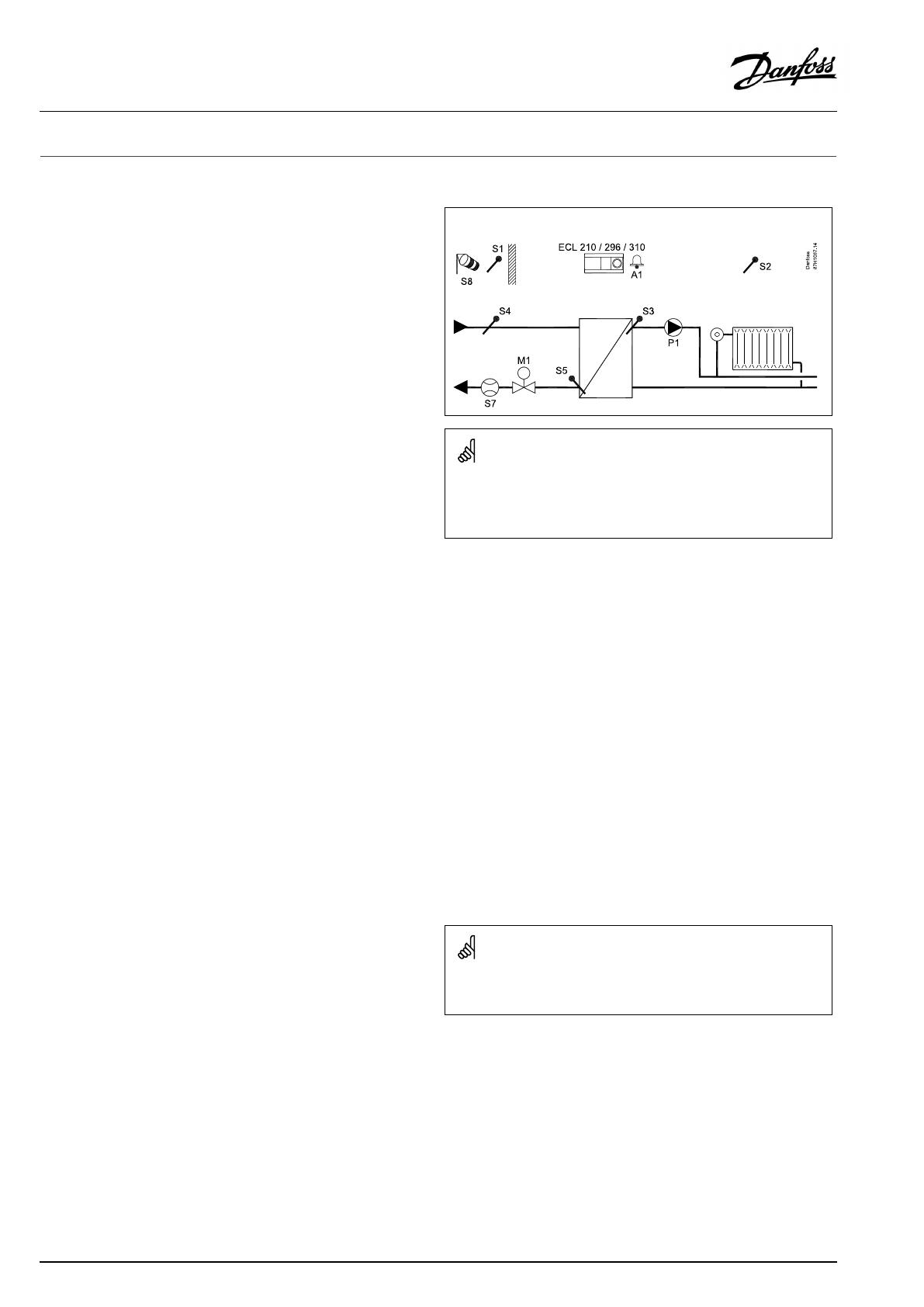
TheapplicationA230isveryflexible.Thesearethebasicprinciples:
Heating(applicationA230.1):
Typically,theflowtemperatureisadjustedaccordingtoyour
requirements.TheflowtemperaturesensorS3isthemost
importantsensor.ThedesiredflowtemperatureatS3iscalculated
intheECLcontroller,basedontheoutdoortemperature(S1)and
thedesiredroomtemperature.
Thelowertheoutdoortemperature,thehigherthedesiredflow
temperature.
Bymeansofaweekschedule,theheatingcircuitcanbein
‘Comfort’or‘Saving’mode.Theweekschedulecanhaveupto3
‘Comfort’periods/day.Avalueforthedesiredroomtemperature
canbesetineachofthemodes.
InSavingmodetheheatingcanbereducedorswitchedofftotally.
ThemotorizedcontrolvalveM1isopenedgraduallywhenthe
flowtemperatureislowerthanthedesiredflowtemperatureand
viceversa.
ThereturntemperatureS5tothedistrictheatingsupplyshouldnot
betoohigh.Ifso,thedesiredflowtemperaturecanbeadjusted
(typicallytoalowervalue),thusresultinginagradualclosingof
themotorizedcontrolvalve.
Inboiler-basedheatingsupplythereturntemperatureshouldnot
betoolow(sameadjustmentprocedureasabove).
Furthermore,thereturntemperaturelimitationcanbedependent
oftheoutdoortemperature.Typically,thelowertheoutdoor
temperature,thehighertheacceptedreturntemperature.
Ifthemeasuredroomtemperature(directlyconnectedtemperature
sensorESM-10(S2)orRemotecontrolunitECA30/31)doesnot
equalthedesiredroomtemperature,thedesiredflowtemperature
canbeadjusted.
Thecirculationpump,P1,isONatheatdemandoratfrost
protection.
TheheatingcanbeswitchedOFFwhentheoutdoortemperatureis
higherthanaselectablevalue.
Aconnectedfloworenergymeterbasedonpulses(S7)canlimit
thefloworenergytoasetmaximumvalue.Furthermore,the
limitationcanbeinrelationtotheoutdoortemperature.Typically,
thelowertheoutdoortemperature,thehighertheacceptedflow/
power.WhenthissubtypeisusedinanECLComfort296or310the
flow/energysignalcanalternativelycomeasanM-bussignal.
Thefrostprotectionmodemaintainsaselectableflowtemperature,
forexample10°C.
Tocompensatefortheinfluenceofwind,awindspeedsensorcan
beconnected.Basedonthewindspeedsensorsignal(0-10V),the
controllercanbesettoincreasethedesiredflowtemperaturein
relationtoincreasedwindspeed.
Unusedinputscan,bymeansofanoverrideswitchorrelaycontact,
beusedforoverridingthescheduletoafixed'Comfort','Saving' ,
'Frostprotection'or'Constanttemperature'mode.
Analarmcanbeactivatediftheactualflowtemperaturediffers
fromthedesiredflowtemperature.
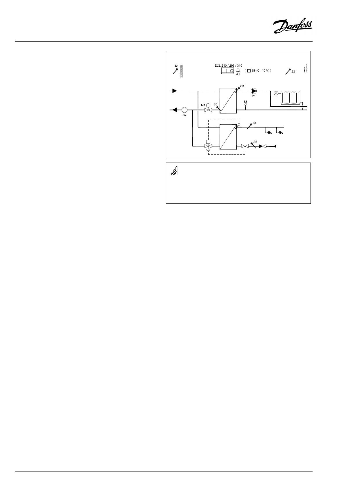
TypicalA230.1application:
Theshowndiagramisafundamentalandsimplifiedexampleanddoes
notcontainallcomponentsthatarenecessaryinasystem.
AllnamedcomponentsareconnectedtotheECLComfortcontroller.
Listofcomponents:
ECL210/296/
310
ElectroniccontrollerECLComfort210,296or310
S1
Outdoortemperaturesensor
S2
(Optional)Roomtemperaturesensor/ECA30
S3
Flowtemperaturesensor
S4
(Optional)Supplyflowtemperaturesensor
(read-outonly)
S5
(Optional)Returntemperaturesensor
S7
(Optional)Flow/energymeter(pulsesignal)
S8
(Optional)Windspeedsensor
P1
Circulationpump,heating
M1
Motorizedcontrolvalve,3-pointcontrolled
Alternative1:Controlvalve,thermo-actuator
controlled(DanfosstypeABV)
Alternative2(ECL310withECA32):Motorized
controlvalve,0-10Voltcontrolled
A1
Alarm
TheA230.1applicationcanutilizeaconnectedflow/energymeter
tolimittheflow/power.
6|©Danfoss|2017.05
VI.LG.H4.02
OperatingGuideECLComfort210/296/310,applicationA230
Cooling(applicationA230.2):
Typically,theflowtemperatureisadjustedaccordingtoyour
requirements.TheflowtemperaturesensorS3isthemost
importantsensor.ThedesiredflowtemperatureatS3issetinthe
ECLcontroller.Furthermore,theoutdoortemperature(S1)can
influencethedesiredflowtemperature.Thehighertheoutdoor
temperature,thelowerthedesiredflowtemperature.
Bymeansoftheweekschedule,thecoolingcircuitcanbein
‘Comfort’or‘Saving’mode(twovaluesforthedesiredflow
temperature).
Theweekschedulealsocontrolstwovalues(‘Comfort’and
‘Saving’)forthedesiredroomtemperature.Ifthemeasuredroom
temperaturedoesnotequalthedesiredroomtemperature,the
desiredflowtemperaturecanbeadjusted.
ThemotorizedcontrolvalveM1isopenedgraduallywhenthe
flowtemperatureishigherthanthedesiredflowtemperatureand
viceversa.
ThereturntemperatureS5tothecoolingsupplyshouldnotbetoo
low.Ifso,thedesiredflowtemperaturecanbeadjusted(typicallyto
ahighervalue),thusresultinginagradualclosingofthemotorized
controlvalve.
Thecirculationpump,P1,isONatcoolingdemand.
Anexternalsignalforthedesiredflowtemperaturecanbeapplied
asa0–10voltsignaltotheterminalsforS8.
Aconnectedfloworenergymeterbasedonpulses(S7)canlimit
thefloworenergytoasetmaximumvalue.
WhentheA230.2isusedinanECLComfort296/310theflow/
energysignalcanalternativelycomeasanM-bussignal.
Thestandbymodemaintainsaselectableflowtemperature,for
example30°C.
ThetemperaturesS4andS6areusedformonitoringpurposesonly.
Theschedulein"Commoncontrollersettings"controlstherelays
2and3.Thiscanbeutilizedforshiftingbetweentwocirculation
pumps.
Seetheinstallationguide,appl.A230.2,ex.dandrelatedelectrical
connections.
Heating(A230.4)
ThissubtypeworksassubtypeA230.1,butthewindinfluence
functionalityisnotimplemented.
Inaddition,A230.4canmonitorDHW(DomesticHotWater)
temperaturesS4andS6.
Anappliedvoltagesignal(0-10Volt)toS8canbeusedfor:
•pressuremeasuring.ThevoltageisconvertedintheECL
controllertoapressure,measuredinbar
or
•settingthedesiredflowtemperature.Thevoltageisconverted
intheECLcontrollertoatemperaturevalue.
TypicalA230.2application:
Theshowndiagramisafundamentalandsimplifiedexampleanddoes
notcontainallcomponentsthatarenecessaryinasystem.
AllnamedcomponentsareconnectedtotheECLComfortcontroller.
Listofcomponents:
ECL210/296
/310
ElectroniccontrollerECLComfort210,296or310
S1
(Optional)Outdoortemperaturesensor
S2
(Optional)Roomtemperaturesensor/ECA30
S3
Flowtemperaturesensor,cooling
S4
(Optional)Supplyflowtemperaturesensor(read-out
only)
S5
(Optional)Returntemperaturesensor
S6
(Optional)Returntemperaturesensor(read-outonly)
S7
(Optional)Flow/energymeter(pulsesignal),not
illustrated
(S8)
(Optional)(Externalvoltage(0–10V)forexternal
settingofdesiredflowtemperature)
P1
Circulationpump,cooling
P2/P3
Schedule2
M1
Motorizedcontrolvalve,3-pointcontrolled
Alternative1:Controlvalve,thermo-actuator
controlled(DanfosstypeABV)
Alternative2(ECL310withECA32):Motorized
controlvalve,0-10Voltcontrolled
TheA230.2applicationcanutilizeaconnectedflow/energymeter
tolimittheflow/power.
VI.LG.H4.02
©Danfoss|2017.05|7
OperatingGuideECLComfort210/296/310,applicationA230
A230,ingeneral:
UptotwoRemoteControlUnits,ECA30/31,canbeconnectedto
oneECLcontrollerinordertocontroltheECLcontrollerremotely.
Exerciseofcirculationpumpsandcontrolvalveinperiodswithout
heatingorcoolingdemandcanbearranged.
AdditionalECLComfortcontrollerscanbeconnectedviatheECL
485businordertoutilizecommonoutdoortemperaturesignal,
timeanddatesignals.
SeveralECLcontrollers,internallyconnectedviaECL485bus,work
inMaster/Slaveconnection.InaMaster/Slavesystemmaximum
2ECA30/31canbepresent.
Anunusedinputcan,bymeansofanoverrideswitch,beusedto
overridethescheduletoafixed:
(A230.1andA230.4):
'Comfort','Saving' ,'Frostprotection'or'Constanttemperature'
mode
(A230.2):
'Comfort'or'Saving'mode
ModbuscommunicationtoaSCADAsystemcanbeestablished.
TheM-busdata(ECLComfort296/310)canfurthermorebe
transferredtotheModbuscommunication.
Alarm
A230.1:
AlarmA1(=relay4)canbeactivatedif:
•theactualflowtemperaturediffersfromthedesiredflow
temperature.
•atemperaturesensororitsconnectiondisconnects/short
circuits.(See:Commoncontrollersettings>System>Raw
inputoverview).
A230.2:
Alarmrelay4isnotused,butatemperaturesensororits
connectionscanbemonitored.
(See:Commoncontrollersettings>System>Rawinputoverview).
A230.4:
AlarmA1(=relay4)canbeactivatedif:
•theactualflowtemperaturediffersfromthedesiredflow
temperature.
•theactualpressureisnotinsideanacceptablepressurerange
•atemperaturesensororitsconnectiondisconnects/short
circuits.(See:Commoncontrollersettings>System>Raw
inputoverview).
Ameasuredtemperaturecanbeoffsetadjusted,ifneeded.
Inputconfiguration
Inputs(asfromS7andup)whicharenotpartoftheapplicationcan
beconfiguredtobePt1000,0-10Volt,frequency(pulsecounter)
orDigitalinput.ThisfeaturemakesitpossibleinECL296/310to
communicateextrasignals,suchastemperatures,pressures,ON/
OFFconditions,viaModbusandECLPortal.
TheconfigurationisdonebymeansoftheECLTool(freesoftware
fordownload)ordirectlyinadedicatedmenuintheECLPortalor
theconnectionforModbus(BMS/SCADA).
TypicalA230.4application:
Theshowndiagramisafundamentalandsimplifiedexampleanddoes
notcontainallcomponentsthatarenecessaryinasystem.
AllnamedcomponentsareconnectedtotheECLComfortcontroller.
Listofcomponents:
ECL210/296
/310
ElectroniccontrollerECLComfort210,296or310
S1
Outdoortemperaturesensor
S2
(Optional)Roomtemperaturesensor/ECA30
S3
Flowtemperaturesensor,
S4
(Optional)DHWflowtemperaturesensor(read-out
only)
S5
(Optional)Returntemperaturesensor
S6
(Optional)DHWcirculationreturntemperature
sensor(read-outonly)
S7
(Optional)Flow/energymeter(pulsesignal)
S8
(Optional)0-10Voltsignalfrompressuresensor
Alternative:0-10Voltsignalforexternalsettingof
desiredflowtemperature
P1
Circulationpump,heating
M1
Motorizedcontrolvalve,3-pointcontrolled
Alternative1:Controlvalve,thermo-actuator
controlled(DanfosstypeABV)
Alternative2(ECL310withECA32):Motorized
controlvalve,0-10Voltcontrolled
A1
Alarm
8|©Danfoss|2017.05
VI.LG.H4.02
OperatingGuideECLComfort210/296/310,applicationA230

A230,ingeneral(continued):
Commissioning
WhentheA230applicationhasbeenuploadedtheECLComfort
controllerstartsinManualmode.Thiscanbeusedtoverifycorrect
connectionsoftemperature,pressureandflowsensors.Also
verifyingthecontrolledcomponentsforcorrectfunctionalitycan
bedone.
Dependingonsystemtype,itmightbenecessarytochangesome
factorysettingsindividuallyinordertooptimizethefunctionality.
Theapplicationkeymustbeinsertedinordertochangesettings.
Important:
•Setthecorrectrunningtime"Mrun"oftheMotorizedControl
ValveM1.(Circuit1>MENU>Settings>Controlparameters
>Mrun).
Thecontrollerispre-programmedwithfactorysettingsthatareshown
inthe‘ParameterIDoverview’appendix.
VI.LG.H4.02
©Danfoss|2017.05|9
OperatingGuideECLComfort210/296/310,applicationA230

2.2Identifyingthesystemtype
Sketchyourapplication
TheECLComfortcontrollerseriesisdesignedforawiderange
ofheating,domestichot-water(DHW)andcoolingsystemswith
differentconfigurationsandcapacities.Ifyoursystemdiffers
fromthediagramsshownhere,youmaywanttomakeasketch
ofthesystemabouttobeinstalled.Thismakesiteasiertouse
theOperatingGuide,whichwillguideyoustep-by-stepfrom
installationtofinaladjustmentsbeforetheend-usertakesover.
TheECLComfortcontrollerisauniversalcontrollerthatcanbe
usedforvarioussystems.Basedontheshownstandardsystems,
itispossibletoconfigureadditionalsystems.Inthischapteryou
findthemostfrequentlyusedsystems.Ifyoursystemisnotquite
asshownbelow,findthediagramwhichhasthebestresemblance
withyoursystemandmakeyourowncombinations.
SeetheInstallationGuide(deliveredwiththeapplicationkey)for
applicationtypes/sub-types.
Thecirculationpump(s)inheatingcircuit(s)canbeplacedintheflow
aswellasthereturn.Placethepumpaccordingtothemanufacturer’s
specification.
10|©Danfoss|2017.05
VI.LG.H4.02
OperatingGuideECLComfort210/296/310,applicationA230

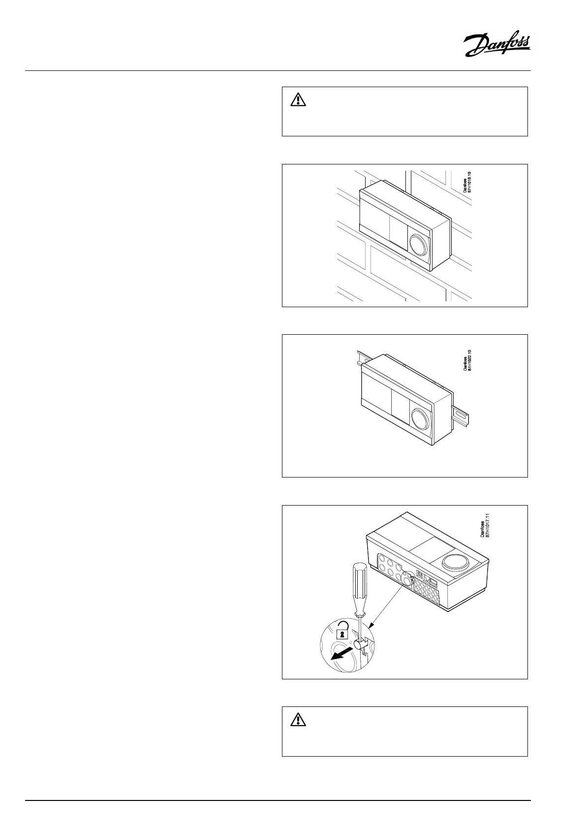
2.3Mounting
2.3.1MountingtheECLComfortcontroller
SeetheInstallationGuidewhichisdeliveredtogetherwiththe
ECLComfortcontroller.
Foreasyaccess,youshouldmounttheECLComfortcontrollernear
thesystem.
ECLComfort210/296/310canbemounted
•onawall
•onaDINrail(35mm)
ECLComfort296canbemounted
•inapanelcut-out
ECLComfort210canbemountedinanECLComfort310basepart
(forfutureupgrade).
Screws,PGcableglandsandrawlplugsarenotsupplied.
LockingtheECLComfort210/310controller
InordertofastentheECLComfortcontrollertoitsbasepart,secure
thecontrollerwiththelockingpin.
Topreventinjuriestopersonsorthecontroller,thecontrollerhasto
besecurelylockedintothebase.Forthispurpose,pressthelocking
pinintothebaseuntilaclickisheardandthecontrollernolonger
canberemovedfromthebase.
Ifthecontrollerisnotsecurelylockedintothebasepart,thereisarisk
thatthecontrollerduringoperationcanunlockfromthebaseandthe
basewithterminals(andalsothe230Va.c.connections)areexposed.
Topreventinjuriestopersons,alwaysmakesurethatthecontroller
issecurelylockedintoitsbase.Ifthisisnotthecase,thecontroller
shouldnotbeoperated!
VI.LG.H4.02
©Danfoss|2017.05|11
OperatingGuideECLComfort210/296/310,applicationA230
Theeasywaytolockthecontrollertoitsbaseorunlockitistousea
screwdriveraslever.
Mountingonawall
Mountthebasepartonawallwithasmoothsurface.Establishthe
electricalconnectionsandpositionthecontrollerinthebasepart.
Securethecontrollerwiththelockingpin.
MountingonaDINrail(35mm)
MountthebasepartonaDINrail.Establishtheelectrical
connectionsandpositionthecontrollerinthebasepart.Secure
thecontrollerwiththelockingpin.
DismountingtheECLComfortcontroller
Inordertoremovethecontrollerfromthebasepart,pulloutthe
lockingpinbymeansofascrewdriver.Thecontrollercannowbe
removedfromthebasepart.
Theeasywaytolockthecontrollertoitsbaseorunlockitistousea
screwdriveraslever.
12|©Danfoss|2017.05
VI.LG.H4.02
OperatingGuideECLComfort210/296/310,applicationA230
BeforeremovingtheECLComfortcontrollerfromthebasepart,ensure
thatthesupplyvoltageisdisconnected.
2.3.2MountingtheRemoteControlUnitsECA30/31
Selectoneofthefollowingmethods:
•Mountingonawall,ECA30/31
•Mountinginapanel,ECA30
Screwsandrawlplugsarenotsupplied.
Mountingonawall
MountthebasepartoftheECA30/31onawallwithasmooth
surface.Establishtheelectricalconnections.PlacetheECA30/
31inthebasepart.
Mountinginapanel
MounttheECA30inapanelusingtheECA30framekit(ordercode
no.087H3236).Establishtheelectricalconnections.Securethe
framewiththeclamp.PlacetheECA30inthebasepart.TheECA
30canbeconnectedtoanexternalroomtemperaturesensor.
TheECA31mustnotbemountedinapanelifthehumidity
functionistobeused.
VI.LG.H4.02
©Danfoss|2017.05|13
OperatingGuideECLComfort210/296/310,applicationA230
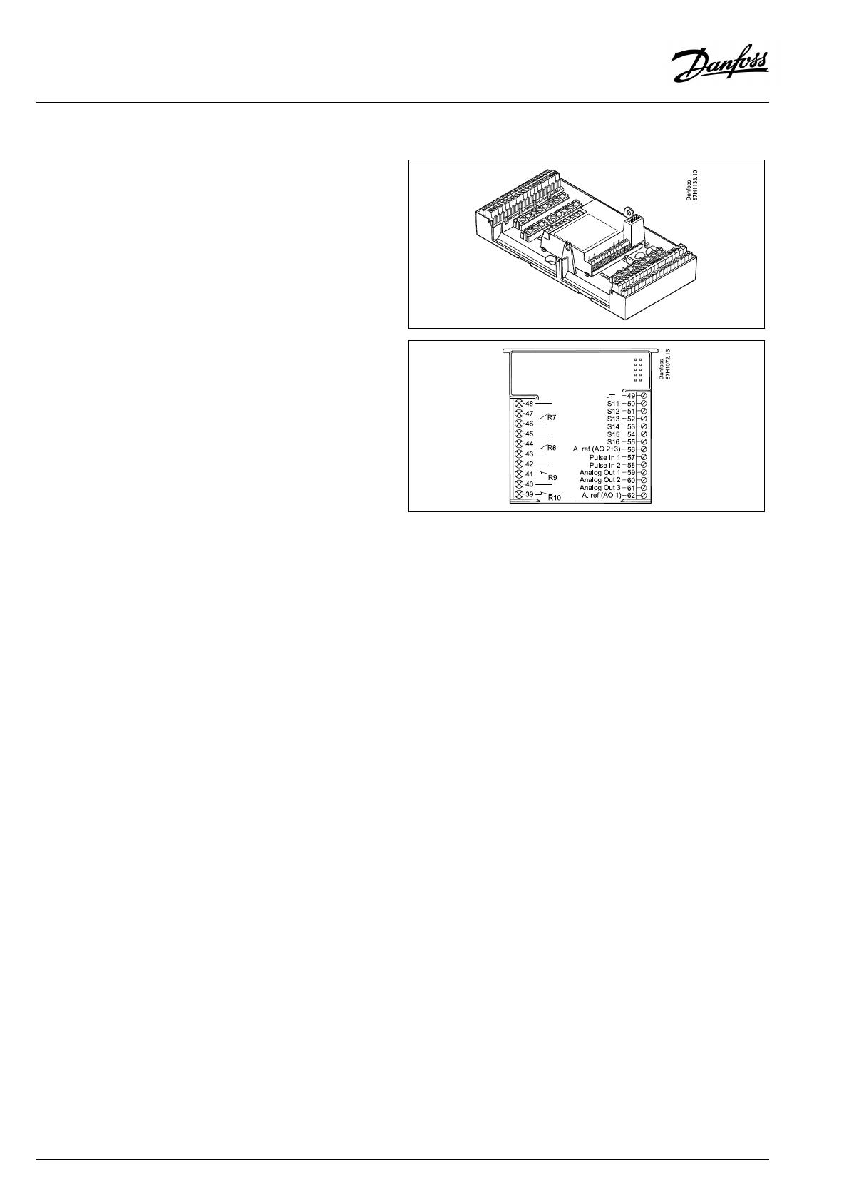
2.3.3MountingtheinternalI/OmoduleECA32
MountingoftheinternalI/OmoduleECA32
TheECA32module(ordercodeno.087H3202)mustbeinserted
intotheECLComfort310/310Bbasepartforadditionalinputand
outputsignalsinrelevantapplications.
TheconnectionbetweentheECLComfort310/310BandECA32
isa10-pole(2x5)connector.Theconnectionisautomatically
establishedwhentheECLComfort310/310Bisplacedonthe
basepart.
14|©Danfoss|2017.05
VI.LG.H4.02
OperatingGuideECLComfort210/296/310,applicationA230
2.4Placingthetemperaturesensors
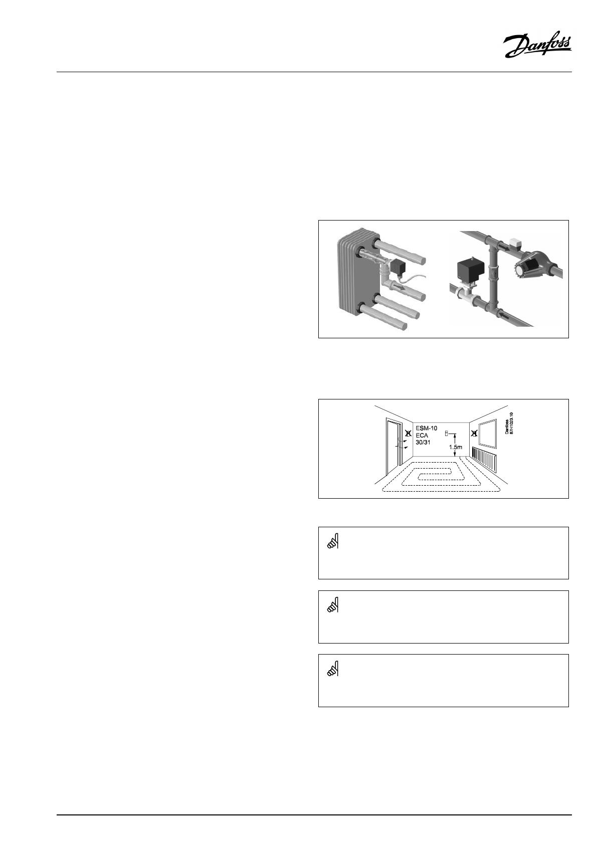
2.4.1Placingthetemperaturesensors
Itisimportantthatthesensorsaremountedinthecorrectposition
inyoursystem.
Thetemperaturesensormentionedbelowaresensorsusedforthe
ECLComfort210/296/310serieswhichnotallwillbeneeded
foryourapplication!
Outdoortemperaturesensor(ESMT)
Theoutdoorsensorshouldbemountedonthatsideofthebuilding
whereitislesslikelytobeexposedtodirectsunshine.Itshouldnot
beplacedclosetodoors,windowsorairoutlets.
Flowtemperaturesensor(ESMU,ESM-11orESMC)
Placethesensormax.15cmfromthemixingpoint.Insystems
withheatexchanger,DanfossrecommendsthattheESMU-typeto
beinsertedintotheexchangerflowoutlet.
Makesurethatthesurfaceofthepipeiscleanandevenwhere
thesensorismounted.
Returntemperaturesensor(ESMU,ESM-11orESMC)
Thereturntemperaturesensorshouldalwaysbeplacedsothatit
measuresarepresentativereturntemperature.
Roomtemperaturesensor
(ESM-10,ECA30/31RemoteControlUnit)
Placetheroomsensorintheroomwherethetemperatureistobe
controlled.Donotplaceitonoutsidewallsorclosetoradiators,
windowsordoors.
Boilertemperaturesensor(ESMU,ESM-11orESMC)
Placethesensoraccordingtotheboilermanufacturer’s
specification.
Airducttemperaturesensor(ESMB-12orESMUtypes)
Placethesensorsothatitmeasuresarepresentativetemperature.
DHWtemperaturesensor(ESMUorESMB-12)
PlacetheDHWtemperaturesensoraccordingtothemanufacturer’s
specification.
Slabtemperaturesensor(ESMB-12)
Placethesensorinaprotectiontubeintheslab.
ESM-11:Donotmovethesensorafterithasbeenfastenedinorderto
avoiddamagetothesensorelement.
ESM-11,ESMCandESMB-12:Useheatconductingpasteforquick
measurementofthetemperature.
ESMUandESMB-12:Usingasensorpockettoprotectthesensorwill,
however,resultinaslowertemperaturemeasurement.
VI.LG.H4.02
©Danfoss|2017.05|15
OperatingGuideECLComfort210/296/310,applicationA230
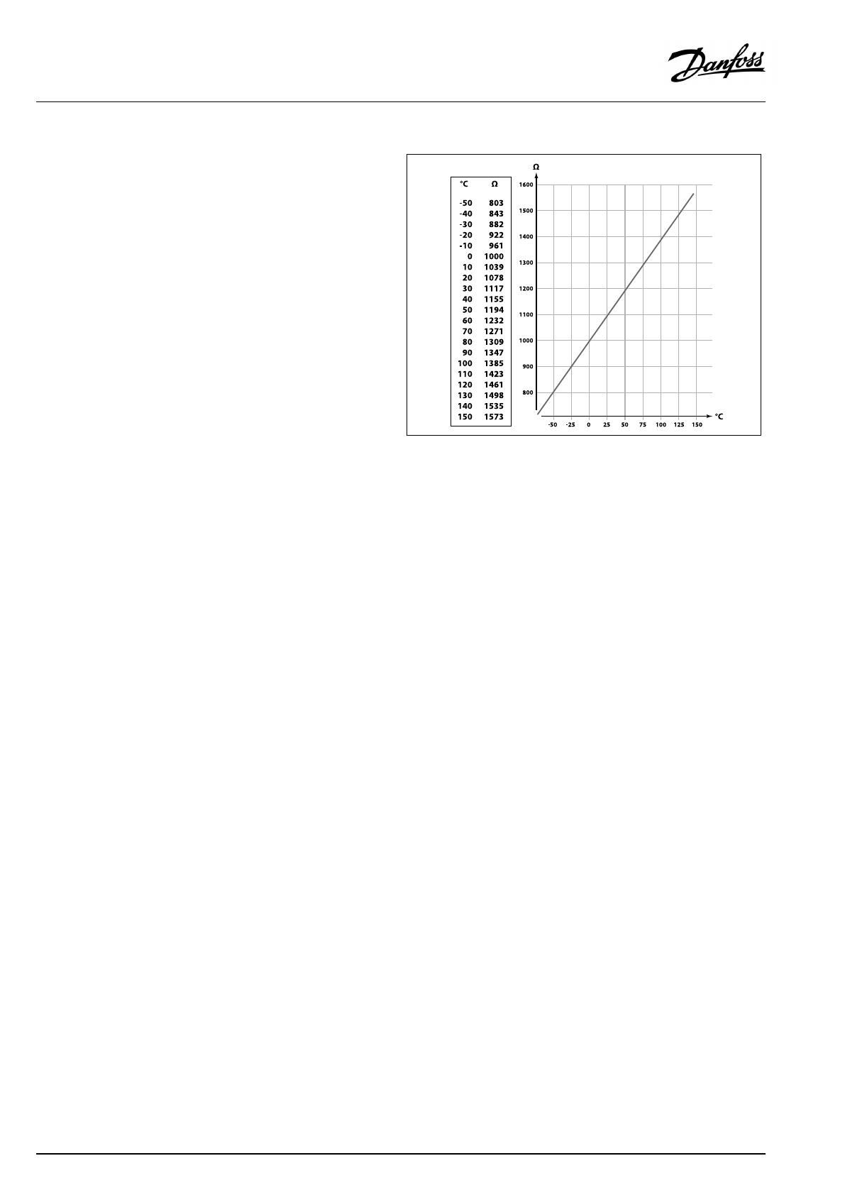
Pt1000temperaturesensor(IEC751B,1000Ω/0°C)
Relationshipbetweentemperatureandohmicvalue:
16|©Danfoss|2017.05
VI.LG.H4.02
OperatingGuideECLComfort210/296/310,applicationA230
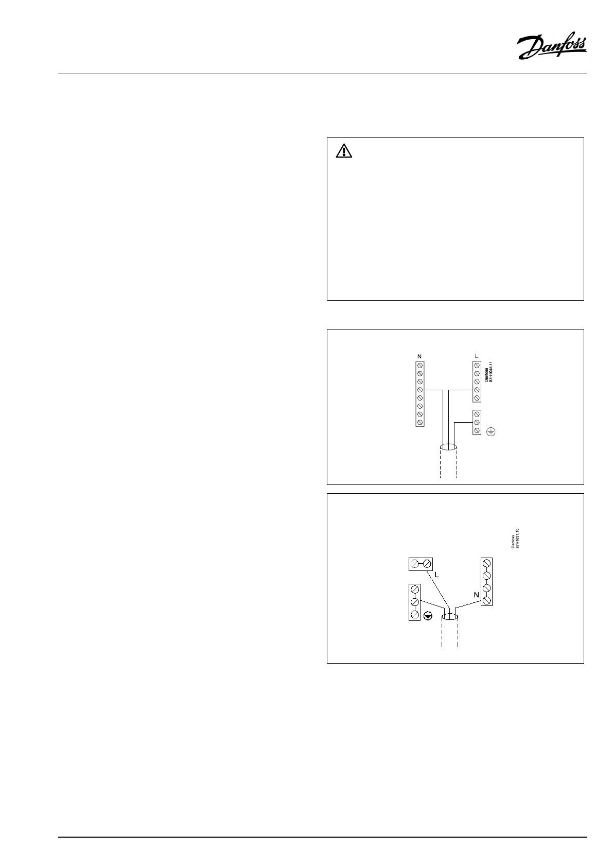
2.5Electricalconnections
2.5.1Electricalconnections230Va.c.
SafetyNote
Necessaryassembly,start-up,andmaintenanceworkmustbe
performedbyqualifiedandauthorizedpersonnelonly.
Locallegislationsmustberespected.Thiscomprisesalsocablesize
andisolation(reinforcedtype).
AfusefortheECLComfortinstallationismax.10Atypically.
TheambienttemperaturerangefortheECLComfortinoperationis
0-55°C.Exceedingthistemperaturerangecanresultinmalfunctions.
Installationmustbeavoidedifthereisariskforcondensation(dew).
Thecommongroundterminalisusedforconnectionofrelevant
components(pumps,motorizedcontrolvalves).
ECL210/310
ECL296
SeealsotheInstallationGuide(deliveredwiththeapplicationkey)
forapplicationspecificconnections.
VI.LG.H4.02
©Danfoss|2017.05|17
OperatingGuideECLComfort210/296/310,applicationA230
Wirecrosssection:0.5-1.5mm²
Incorrectconnectioncandamagetheelectronicoutputs.
Max.2x1.5mm²wirescanbeinsertedintoeachscrewterminal.
Maximumloadratings:
Relayterminals
4(2)A/230Va.c.
(4Aforohmicload,2Afor
inductiveload)
Triac(=electronic
relay)terminals
0,2A/230Va.c.
A230.2(cooling):2-pumpcontrol
ApplicationA230.2,ex.disanexampleforscheduledshiftbetween
twocirculationpumps.
ControlofP1isbasedonthecoolingdemandanddetermines
viaK1theON/OFFcontrolofthepumpsP2andP3.P2andP3
arerelatedtotheoutputoftheschedulein"Commoncontroller
settings".
TheelectricdiagramforA230.2,P2andP3showsanexamplefor
connection.
18|©Danfoss|2017.05
VI.LG.H4.02
OperatingGuideECLComfort210/296/310,applicationA230

2.5.2Electricalconnections24Va.c.
SeealsotheInstallationGuide(deliveredwiththeapplicationkey)
forapplicationspecificconnections.
Maximumloadratings:
Relayterminals
4(2)A/24Va.c.
(4Aforohmicload,2Afor
inductiveload)
Triac(=electronic
relay)terminals
1A/24Va.c.
A230.2(cooling):2-pumpcontrol
ApplicationA230.2,ex.disanexampleforscheduledshiftbetween
2circulationpumps.
ControlofP1isbasedonthecoolingdemandanddetermines
viaK1theON/OFFcontrolofthepumpsP2andP3.P2andP3
arerelatedtotheoutputoftheschedulein"Commoncontroller
settings".
TheelectricdiagramforA230.2,P2andP3showsanexamplefor
connection.
Donotconnect230Va.c.poweredcomponentstoa24Va.c.power
suppliedcontrollerdirectly.Useauxilliaryrelays(K)toseparate230
Va.c.from24Va.c.
VI.LG.H4.02
©Danfoss|2017.05|19
OperatingGuideECLComfort210/296/310,applicationA230

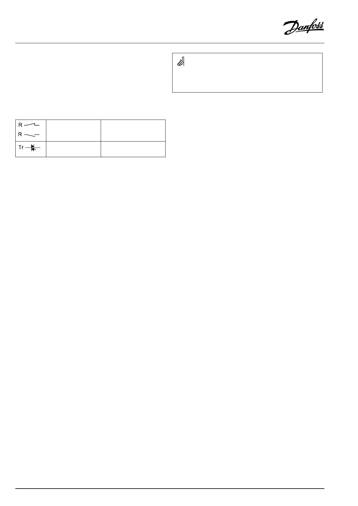
2.5.3Electricalconnections,safetythermostats,ingeneral
SeealsotheInstallationGuide(deliveredwiththeapplicationkey)
forapplicationspecificconnections.
Theconnectiondiagramsshowvarioussolutions/examples:
Safetythermostat,1–stepclosing:
Motorizedcontrolvalvewithoutsafetyfunction
Safetythermostat,1–stepclosing:
Motorizedcontrolvalvewithsafetyfunction
Safetythermostat,2–stepclosing:
Motorizedcontrolvalvewithsafetyfunction
WhenSTisactivatedbyahightemperature,thesafetycircuitinthe
motorizedcontrolvalveclosesthevalveimmediately.
WhenST1isactivatedbyahightemperature(theTRtemperature),the
motorizedcontrolvalveisclosedgradually.Atahighertemperature
(theSTtemperature),thesafetycircuitinthemotorizedcontrolvalve
closesthevalveimmediately.
20|©Danfoss|2017.05
VI.LG.H4.02
OperatingGuideECLComfort210/296/310,applicationA230
/