Honeywell Home T3 Pro Installation Instructions Manual

Category
Thermostats
Type
Installation Instructions Manual
Package Includes:
T3 Pro Thermostat
UWP™ Mounting System
Decorative Cover Plate –
Small; Size 4.72” H X 5.9” W
(120 mm H X 150 mm W)
Screws and Anchors
2 AA Batteries
Thermostat Literature
T3 Pro
Thermostat
Installation Instructions
TH3110U2008,
TH3210U2004
Read before installing
Heat On
Menu
Fan Auto
Optional Cover Plate installation
NOTE: If Optional Cover Plate is not required, see “UWP
Mounting System installation” on next page.
Use the Optional Cover Plate when you need to cover
paint gaps from the old thermostat.
1. Before starting, turn the power off at the breaker box
or switch.
2. Mount the Cover Plate to the wall using any of the 6
screw holes. Insert and tighten the mounting screws
supplied with the Cover Plate. Do not overtighten. See
Figure 1. Make sure the Cover Plate is level.
3. Attach the UWP by hanging it on the top hook of the
Cover Plate and then snapping the bottom of the
UWP in place. See Figure 2.
4. If mounting to a wall with no existing wall anchors:
a. Position the Cover Plate on wall. Level and mark
hole positions. See Figure 1.
b. Drill holes at marked positions, and then lightly
tap supplied wall anchors into the wall using a
hammer.
If your box contains red anchors, drill 7/32” (5.6 mm) holes.
If your box contains yellow anchors, drill 3/16” (4.8 mm) holes.
Use 2x supplied screws (#8 11/2” (38 mm) for red anchors and
#6 11/2” (38 mm) for yellow anchors).
2
1
2
Power options
Insert AA batteries for primary or backup
power.
UWP Mounting System installation
Use 3x supplied
screws (#8 11/2”
(38 mm) for red
anchors and #6
11/2” (38 mm) for
yellow anchors)
1. Before starting, turn the power off
at the breaker box or switch. Open
package to find the UWP. See Figure 1.
2. Position the UWP on wall. Level and
mark hole positions. See Figure 2.
Drill holes at marked positions, and
then lightly tap supplied wall anchors
into the wall using a hammer.
If your box contains red anchors,
drill 7/32” (5.6 mm) holes.
If your box contains yellow anchors,
drill 3/16” (4.8 mm) holes.
3. Pull the door open and insert the wires
through wiring hole of the UWP. See
Figure 3.
4. Place the UWP over the wall anchors.
Insert and tighten mounting screws
supplied with the UWP. Do not
overtighten. Tighten until the UWP
no longer moves. Close the door. See
Figure 4.
NOTE: If Optional Cover Plate is required,
see “Optional Cover Plate installation” on
previous page.
4
1
2
3
S
S
Y
2
U
U
G
C
Y
A
Rc
W
K
W2
R
L/A
O/B
AUX
E
Insert R and C wires into
designated terminals for primary
AC power (C terminal is optional
if batteries are installed, but it is
recommended). Remove wires by
depressing the terminal tabs.
3
UWP Wiring terminal designations
S
Not used for T3
thermostat.
L/A
- A
Not used for T3 thermostat.
S
O/B Changeover valve
Y
Compressor contactor
(stage 1)
AUX -
W2
Auxiliary heat
(TH3210U only)
Y2
Not used for T3
thermostat.
E
Emergency heat
(TH3210U only)
G
Fan W Heat (stage 1)
C
24VAC common. For 2
transformer systems,
use common wire from
cooling transformer.
K Not used for T3 thermostat.
U
Not used for T3
thermostat.
R
24VAC power from heating
transformer*
U
Rc
24VAC power from cooling
transformer*
Note: Not all
terminals may be
used, depending
on the system
type that is being
wired. The most
commonly used
terminals are
shaded.
* Terminal can be jumped using Slider Tab. See “Setting Slider Tabs” above.
Set R Slider Tab.
Use built-in jumper (R Slider Tab)
to differentiate between one or two
transformer systems.
If there is only one R wire, and it is
connected to the R, Rc, or RH terminal, set
the slider to the up position (1 wire).
If there is one wire connected to the R
terminal and one wire connected to the Rc
terminal, set the slider to the down position
(2 wires).
NOTE: Slider Tab for U terminals should be left
in place for T3 Pro models.
Setting Slider Tabs (built-in jumper)
R/Rc Slider Tab
(built-in jumper)
UWP Mounting System
4
1H/1C System (1 transformer)
R Power [1]
Rc [R+Rc joined by Slider Tab] [2]
Y Compressor contactor
C 24VAC common [3]
W Heat
G Fan
Heat-only System
R Power [1]
Rc [R+Rc joined by Slider Tab] [2]
C 24VAC common [3]
W Heat
Heat-only System (Series 20) [5]
R Series 20 valve terminal “R” [1]
Rc [R+Rc joined by Slider Tab] [2]
Y Series 20 valve terminal “W
C 24VAC common [3]
W Series 20 valve terminal “B”
Heat-only System
(power open zone valve) [5]
R Power [1]
Rc [R+Rc joined by Slider Tab] [2]
W Valve
C 24VAC common [3]
1H/1C System (2 transformers)
R Power (heating transformer) [1]
Rc Power (cooling transformer) [1]
Y Compressor contactor
C 24VAC common [3, 4]
W Heat
G Fan
Heat-only System with Fan
R Power [1]
Rc [R+Rc joined by Slider Tab] [2]
C 24VAC common [3]
W Heat
G Fan
Cool-only System
R Power [1]
Rc [R+Rc joined by Slider Tab] [2]
Y Compressor contactor
C 24VAC common [3]
G Fan
1H/1C Heat Pump System
R Power [1]
Rc [R+Rc joined by Slider Tab] [2]
Y Compressor contactor
C 24VAC common [3]
O/B Changeover valve [7]
G Fan
W Do not use this terminal for heat pump
applications!
2H/1C Heat Pump System (TH3210U only)
R Power [1]
Rc [R+Rc joined by Slider Tab] [2]
Y Compressor contactor
C 24VAC common [3]
O/B Changeover valve [7]
G Fan
AUX Auxiliary heat
E Emergency heat
W Do not use this terminal for heat pump
applications!
Wiring heat pump systems
Wiring conventional systems: forced air and hydronics
NOTES
Wire specifications: Use 18 to 22-gauge thermostat wire. Shielded cable is not required.
[1] Power supply. Provide disconnect means and overload
protection as required.
[2] Move RSlider Tab on UWP to the R setting. For more
information, see “Setting Slider Tabs (built-in jumper)” on
page 3
[3] Optional 24VAC common connection.
[4] Common connection must come from cooling transformer.
[5] In ISU set Heat system type to Radiant Heat. Set number of
cool stages to 0.
[7] In Installer Setup, set changeover valve to O (for cool
changeover) or B (for heat changeover).
5
Thermostat mounting
1. Push excess wire back into the wall
opening.
2. Close the UWP door. It should remain
closed without bulging.
3. Align the UWP with the thermostat, and
push gently until the thermostat snaps in
place.
4. Turn the power on at the breaker box or
switch.
System operation settings
1. Press Menu, and then press the Mode (+)
button to cycle to the next available
System mode.
2. Cycle through the modes until the required
System mode is displayed, and then press
Done.
NOTE: Available System modes vary by model
and system settings.
System modes:
Auto: Thermostat selects heating or cooling as needed.
Heat: Thermostat controls only the heating system.
Cool: Thermostat controls only the cooling system.
Em heat (TH3210U only): For heat pumps with auxiliary heat. Thermostat
controls auxiliary heat. Compressor is not used.
Off: Heating and cooling system is off. Fan will still operate if fan is set to
On.
NOTE: Heat On/Cool On may flash for 5 minutes due to compressor protection.
Fan operation settings
1. Press Menu, and then press the Fan (-)
button to cycle to the next available
Fan mode.
2. Cycle through the modes until the
required Fan mode is displayed, then
press Done.
NOTE: Available Fan modes vary with
system settings.
Fan modes:
Auto: Fan runs only when the
heating or cooling system is on.
On: Fan is always on.
6
Installer setup (ISU)
NOTE: The thermostat enters installer setup the first time it is powered up during
installation. To re-enter the System Setup from the Home Screen, press and hold
the Menu button for approximately 5 seconds.
1. Select System Setup options.
Press Edit (-) to change values or select from available options. Then press Next
(+) to save changes and advance to the next System Setup number.
See “System Setup options” on the next page for a full list of
System Setup
numbers and options
.
Repeat until all of the System Setup options have been set, and then press
Done. The thermostat will save and exit to the home screen.
2. Continue to “Installer setup (ISU)” on page 6.
Setup number
Option number
7
Installer setup (ISU)
ISU Setup Number and Description Options (factory default in bold)
125 = Temperature Indication Scale
0 = Fahrenheit
1 = Celsius
200 = Heating System Type
1 = Conventional Forced Air Heat
2 = Heat Pump
3 = Radiant Heat
5 = None (Cool Only)
Notes:
Default varies based on model.
This option selects the basic system type your thermostat will
control.
205 = Heating Equipment Type
Conventional Forced Air Heat:
1 = Standard Efficiency Gas Forced Air
2 = High Efficiency Gas Forced Air
3 = Oil Forced Air
4 = Electric Forced Air
5 = Hot Water Fan Coil
Heat Pump:
Note: ISU 205 is not shown when ISU 200 is set for heat pump.
Radiant Heat:
9 = Hot Water Radiant Heat
12 = Steam
Note: This option selects the equipment type your thermostat will
control. This feature is NOT displayed if feature 200 is set to Cool Only.
218 = Reversing Valve O/B
0 = O (O/B in Cool)
1 = B (O/B in Heat)
Note: This option is only displayed if the Heat Pump is configured. Select
whether reversing valve O/B should energize in cool or in heat.
220 = Cool Stages / Compressor Stages
(200=Conv / 200=HP)
0, 1
Note: Select how many Cool or Compressor stages of your equipment
the thermostat will control. Set value to 0 if you do not have Cool Stage/
Compressor Stage.
221 = Heat Stages / Backup Heat Stages
Heat Stages: 1
Backup Heat Stages: 0, 1
Note: Select how many Heat or Aux/E stages of your equipment the
thermostat will control.
230 = Fan Control in Heat
1 = Equipment Controls Fan
2 = Thermostat Controls Fan
Note: This ISU is only displayed if ISU 205 is set to Electric Forced Air or
Fan Coil.
300 = System Changeover
0 = Manual
1 = Automatic
Note: Thermostat can automatically control both heating and cooling
to maintain the desired indoor temperature. To be able to select
“automatic” system mode on thermostat home screen, turn this feature
ON. Turn OFF if you want to control heating or cooling manually.
Continued on next page.
8
ISU Setup Number and Description Options (factory default in bold)
303 = Auto Changeover Differential
0 °F to 5 °F
0 °C to 2.5 °C
Note: Differential is NOT deadband. Differential means how far past the
setpoint before switching to the mode selected. Deadband setup is not
an option. An advanced algorithm fixes the deadband at 0 °F. This is
more advanced than previous thermostats.
340 = Backup Heat Droop
(TH3210U only)
0 = Comfort
2 = 2 °F
3 = 3 °F
4 = 4 °F
5 = 5 °F
6 = 6 °F
7 = 7 °F
8 = 8 °F
9 = 9 °F
10 = 10 °F
11 = 11 °F
12 = 12 °F
13 = 13 °F
14 = 14 °F
15 = 15 °F
350 = Upstage Timer to Backup Heat
(TH3210U only)
0 = Off
1 = 30 minutes
2 = 45 minutes
3 = 60 minutes
4 = 75 minutes
5 = 90 minutes
6 = 2 hours
7 = 3 hours
8 = 4 hours
10 = 5 hours
365 = Compressor Cycle Rate (Stage 1)
1 - 6
Note: This ISU is only displayed when Cool /Compressor Stage is set to
1 stage. Cycle rate limits the maximum number of times the system can
cycle in a 1 hour period measured at a 50% load. For example, when
set to 3 CPH, at a 50% load, the most the system will cycle is 3 times
per hour (10 minutes on, 10 minutes off). The system cycles less often
when load conditions are less than or greater than a 50% load.
370 = Heating Cycle Rate (Stage 1)
1 - 12
Note: This ISU is only displayed when Heat Stage is set to 1 stage. Cycle
rate limits the maximum number of times the system can cycle in a 1
hour period measured at a 50% load. For example, when set to 3 CPH,
at a 50% load, the most the system will cycle is 3 times per hour (10
minutes on, 10 minutes off). The system cycles less often when load
conditions are less than or greater than a 50% load. The recommended
(default) cycle rate settings are below for each heating equipment type:
Standard Efficiency Gas Forced Air = 5 CPH; High Efficiency Gas Forced
Air = 3 CPH; Oil Forced Air = 5 CPH; Electric Forced Air = 9 CPH; Fan Coil
= 3 CPH; Hot Water Radiant Heat = 3 CPH; Steam = 1 CPH.
375 = Heating Cycle Rate Auxiliary Heat
(TH3210U only)
1 - 12
387 = Compressor Protection
0 = Off
1 - 5 minutes
Note: The thermostat has a built in compressor protection (minimum
off timer) that prevents the compressor from restarting too early after
a shutdown. The minimum-off timer is activated after the compressor
turns off. If there is a call during the minimum-off timer, the thermostat
shows “Wait” in the display. This ISU is displayed if ISU 220 is set to at
least 1 stage.
Installer setup (ISU) (continued)
9
ISU Setup Number and Description Options (factory default in bold)
430 = Minimum Cool Setpoint
50 °F to 99 °F (50 °F)
10.0 °C to 37.0 °C (10.0 °C)
Note: The cool temperature cannot be set below this level.
431 = Maximum Heat Setpoint
32 °F to 90 °F (90 °F)
0 °C to 32.0 °C (32 °C)
Note: The heat temperature cannot be set above this level.
1400 = Backlighting
0 = On Demand
1 = Continuous
Note: Common wire needed for continuous.
1401 = Backlight Brightness
1 - 5
Note: Only displayed if continuous backlight selected.
1420 = Temperature Display Offset
3 °F to 3 °F (0 °F)
1.5 °C to 1.5 °C (0 °C)
Note: 0 °F = No difference in displayed temperature and the actual room
temperature. The thermostat can display up to 3 °F (1.5 °C) lower or
higher than the actual measured temperature.
NOTE: Once you have cycled through all of the System Setup numbers, press
Done to save and exit to the home screen.
Setup Complete
You have now finished installing and setting up your thermostat.
Installer setup (ISU) (continued)
10
Specifications
Temperature Ranges
Heat: 32 °F to 90 °F (0 °C to 32.0 °C)
Cool: 50 °F to 99 °F (10.0 °C to 37.0 °C)
Operating Ambient Temperature
32 °F to 102 °F (0 °C to 38.9 °C)
Shipping Temperature
20 °F to 120 °F (28.9 °C to 48.9 °C)
Operating Relative Humidity
5% to 90% (non-condensing)
Physical Dimensions in inches (mm) (H x W x D)
Thermostat: 3.86” H x 5.36” W x 1.08” D
(98 mm H x 136 mm W x 27.4 mm D)
Decorative Cover Plate – Small; size:
4.72” H X 5.9” W (120 mm H X 150 mm W)
Electrical Ratings
Terminal Voltage (50Hz/60Hz) Running Current
W Heating 20 Vac30 Vac 0.02 A1.0 A
W2 (Aux) Heating (TH3210U only) 20 Vac30 Vac 0.02 A1.0 A
E Emergency Heat (TH3210U only) 20 Vac30 Vac 0.02 A0.5 A
Y Compressor Stage 1 20 Vac30 Vac 0.02 A1.0 A
G Fan 20 Vac30 Vac 0.02 A0.5 A
O/B Changeover 20 Vac30 Vac 0.02 A0.5 A
Troubleshooting
If you have difficulty with your thermostat, please try the following suggestions. Most problems can be
corrected quickly and easily.
Display is blank Check circuit breaker and reset if necessary.
Make sure power switch for heating & cooling system is on.
Make sure furnace door is closed securely.
Make sure fresh AA alkaline batteries are correctly installed (see page 2).
Heating or cooling
system does not
respond
Press Mode button to set system Heat (see page 5). Make sure the desired
temperature is set higher than the inside temperature.
Press Mode button to set system Cool (see page 5). Make sure the desired
temperature is set lower than the inside temperature.
Check circuit breaker and reset if necessary.
Make sure power switch for heating & cooling system is on.
Make sure furnace door is closed securely.
Wait 5 minutes for the system to respond.
“Cool On” or
“Heat On” is
flashing
Compressor protection feature is engaged. Wait 5 minutes for the system to
restart safely, without damage to the compressor.
Aux heat runs in
cooling
For heat pump systems, verify there is not a wire attached to W on UWP systems.
See “Wiring heat pump systems” on page 4.
Cool runs with a
call for heat
For heat pump systems, verify there is not a wire attached to W on UWP systems.
See “Wiring heat pump systems” on page 4.
11
For assistance with this product, please visit
customer.resideo.com.
Or call Customer Care toll-free at
18004681502.
Customer assistance
Pull to remove the thermostat
from the UWP.
CAUTION: MERCURY NOTICE
If this product is replacing a control that contains mercury in a sealed
tube, do not place the old control in the trash. Contact your local waste
management authority for instructions regarding recycling and proper
disposal.
CAUTION: EQUIPMENT DAMAGE HAZARD
Compressor protection is bypassed during testing. To prevent equipment
damage, avoid cycling the compressor quickly.
CAUTION: ELECTRICAL HAZARD
Can cause electrical shock or equipment damage. Disconnect power before
beginning installation.
33-00520EFS-01
Resideo Technologies Inc.
1985 Douglas Drive North, Golden Valley, MN 55422
18004681502
3300520EFS01 M.S. 0420 | Printed in United Stateswww.resideo.com
© 2020 Resideo Technologies, Inc. All rights reserved.
The Honeywell Home trademark is used under license
from Honeywell International, Inc. This product is manu-
factured by Resideo Technologies, Inc. and its affiliates.
Tous droits réservés. La marque de commerce Honeywell
Home est utilisée avec l’autorisation d’Honeywell
International, Inc.
Ce produit est fabriqué par Resideo Technologies, Inc. et
ses sociétés affiliées.
Todos los derechos reservados. La marca comercial
Honeywell Home se utiliza bajo licencia de Honeywell
International, Inc.
Este producto es fabricado por Resideo Technologies, Inc.
y sus afiliados.
Heat On
Menu
Fan Auto
TH3110U2008,
TH3210U2004
Lire avant l’installation
La boîte comprend :
Thermostat T3 Pro
Système de montage UWP
Plaque décorative – petite;
120 mm H x 150 mm L
(4,72 po H x 5,9 po L)
Vis et chevilles
2 piles AA
Documentation du thermostat
Notice d’installation
T3 Pro
Thermostat
REMARQUE : Si la plaque de recouvrement en option nest
pas requise, consultez la section « Installation du système de
montage UWP » à la page suivante.
Utilisez la plaque de recouvrement en option lorsque vous
devez couvrir les coupures de peinture de l’ancien thermostat.
1. Avant de commencer, coupez l’alimentation au panneau
de distribution ou au disjoncteur.
2. Posez la plaque de recouvrement au mur à l’aide des
6 trous de vis. Insérez et serrez les vis fournies avec le
couvercle de recouvrement. Ne serrez pas excessivement.
Voir la figure 1. Assurez-vous que la plaque de
recouvrement est de niveau.
3. Fixez l’UWP en l’accrochant au crochet supérieur de la
plaque de recouvrement, puis en l’enclenchant en place
par le bas. Voir la figure 2.
4. Fixation au mur sans utiliser les ancrages existants :
a. Positionnez la plaque de recouvrement sur le mur.
Placez-le de niveau, puis marquez l’emplacement des
trous. Voir la figure 1.
b. Percez les trous aux emplacements marqués, puis à l’aide d’un marteau, posez
doucement les ancrages de mur fournis.
Si votre boîte contient des ancrages rouges, percez des trous de 5,6 mm
(7/32 po).
Si votre boîte contient des ancrages jaunes, percez des trous de 4,8 mm
(3/16 po).
Utilisez les deux vis (nº 8 1 1/2 po [38 mm] pour les ancrages rouges et
nº 6 1 1/2 po [38 mm] pour les ancrages jaunes).
Installation de la plaque de couvercle en option
2
1
2
Options dalimentation
Installation du système de montage UWP
Utiliser les 3 vis
fournies (Nº 8 – 1 ½ po
(38 mm) pour les
ancrages rouges;
Nº 6 – 1 ½ po (38 mm)
pour les ancrages
jaunes)
4
1
2
3
1. Avant le démarrage, éteindre
l’alimentation au niveau du disjoncteur
du circuit ou de l’interrupteur. Ouvrir
l’emballage du UWP. Voir la Figure 1.
2. Placer le UWP sur le mur. Le mettre à
niveau et marquer les positions des trous.
Voir la Figure 2.
Percer des trous aux emplacements
marqués, puis taper légèrement sur les
chevilles murales fournies dans le mur à
l’aide d’un marteau.
Si votre boîtier est accompagné
d’ancrages rouges, percez des trous de
7/32 po (5.6 mm).
Si votre boîtier est accompagné
d’ancrages jaunes, percez des trous de
3/16 po (4.8 mm).
3. Ouvrir le couvercle et faire passer les fils
par l’ouverture réservée aux fils du UWP.
Voir la Figure 3.
4. Placer le UWP sur les chevilles murales.
Insérer et serrer les vis de montage
fournies avec le UWP. Ne pas trop serrer.
Serrer jusqu’à ce que le UWP ne bouge
plus. Fermer le couvercle. Voir la Figure 4.
REMARQUE : Si vous devez utiliser la plaque
de recouvrement, consultez la section
« Installation de la plaque de recouvrement
en option » à la page précédente.
S
S
Y
2
U
U
G
C
Y
A
Rc
W
K
W2
R
L/A
O/B
AUX
E
Insérer les fils R et C dans
les bornes désignées pour
l’alimentation principale en courant
alternatif (la borne C est facultative
si les piles sont installées, mais elle
est recommandée). Retirer les fils
en appuyant sur les languettes de
la borne.
Insérer les piles AA pour assurer
l’alimentation principale ou de secours.
3
Caracristiques du terminal de câblage UWP
S
Ne peut être utilisé
pour le câblage du
thermostat T3.
L/A
- A
Ne peut être utilisé pour le
câblage du thermostat T3.
S
O/B Robinet de jumelage
Y
Contacteur de
compresseur (étage 1)
AUX -
W2
Chauffage auxiliaire
(TH3210U seulement)
Y2
Ne peut être utilisé
pour le câblage du
thermostat T3.
E
Chauffage d’urgence
(TH3210U seulement)
G
Ventilateur W Chauffage (étage 1)
C
24 V c.a. commune.
Pour les systèmes à
deux transformateurs,
utiliser le fil commun
du transformateur de
refroidissement.
K
Ne peut être utilisé pour le
câblage du thermostat T3.
U
Ne peut être utilisé
pour le câblage du
thermostat T3.
R
Alimentation 24 V c.a.
du transformateur de
chauffage*
U
Rc
Alimentation 24 V c.a.
du transformateur de
refroidissement*
Remarque : Les
bornes ne peuvent
pas toutes être
utilisées, selon le
type de système
qui est connecté.
Les bornes les
plus couramment
utilisées sont
ombrées.
* La borne peut être reliée à l’aide du curseur. Voir « Réglage des curseurs » ci-dessus.
Régler le curseur R.
Utiliser le commutateur de liaison intégré
(curseur R) pour différencier entre un
l’autre système de transformateur.
S’il n’y a qu’un seul fil R et s’il est connecté
à la borne R, Rc ou RH, régler le curseur sur
la position haute (1 fil).
S’il y a un fil connecté à la borne R et un fil
connecté à la borne Rc, régler le curseur
sur la position basse (2 fils).
REMARQUE : Les curseurs des bornes U
doivent être laissés en position pour les
modèles T3 Pro.
glages des curseurs (cavalier intégré)
Curseur R/Rc
(cavalier intégré)
Système de montage UWP
4
Système à 1 étage de chauffage/1 étage de
refroidissement (1 transformateur)
R Alimentation [1]
Rc [R+Rc liés par le curseur] [2]
Y Contacteur du compresseur
C Borne commune 24 V c.a. [3]
W Chauffage
G Ventilateur
Système de chauffage uniquement
R Alimentation [1]
Rc [R+Rc liés par le curseur] [2]
C Borne commune 24 V c.a. [3]
W Chauffage
Système de chauffage uniquement (Série 20) [5]
R Borne R de vanne série 20 [1]
Rc [R+Rc liés par le curseur] [2]
Y Borne W de vanne série
C Borne commune 24 V c.a. [3]
W Borne B de vanne série 20
Système de chauffage uniquement
(vanne de zone à ouverture motorisée) [5]
R Alimentation [1]
Rc [R+Rc liés par le curseur] [2]
W Vanne
C Borne commune 24 V c.a. [3]
Système à 1 étage de chauffage/1 étage de
refroidissement (2 transformateurs)
R Alimentation (transformateur de chauffage) [1]
Rc Alimentation (transformateur de
refroidissement) [1]
Y Contacteur du compresseur
C Borne commune 24 V c.a. [3, 4]
W Chauffage
G Ventilateur
Système de chauffage uniquement avec
ventilateur
R Alimentation [1]
Rc [R+Rc liés par le curseur] [2]
C Borne commune 24 V c.a. [3]
W Chauffage
G Ventilateur
Système de refroidissement uniquement
R Alimentation [1]
Rc [R+Rc liés par le curseur] [2]
Y Contacteur du compresseur
C Borne commune 24 V c.a. [3]
G Ventilateur
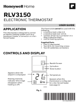
Câblage des systèmes conventionnels : air forcé et hydronique
REMARQUES
Caractéristiques de câblage : Utiliser un fil de thermostat de calibre 18 à 22. Câble blindé non requis.
[1] Alimentation. Assurer au besoin un dispositif de coupure et
une protection contre les surcharges.
[2] Mettre le curseur R de la plaque murale sur R. Pour des
informations supplémentaires, consulter « Réglages des
curseurs (cavalier intégré) » à la page 3.
[3] Connexion commune 24 V c.a. facultative.
[4] La connexion commune doit venir du transformateur de
refroidissement.
[5] Dans la configuration installateur (ISU), régler le type de
système de chauffage sur chauffage rayonnant. Régler le
nombre d’étages de refroidissement sur 0.
[7] Dans la configuration installateur, régler la vanne de com-
mutation sur O (pour commutation de refroidissement) ou
B (pour commutation de chauffage).
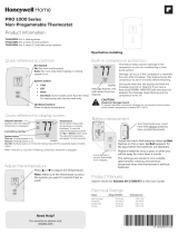
Système de thermopompe à 1 étage de
chauffage/1 étage de refroidissement
R Alimentation [1]
Rc [R+Rc liés par le curseur] [2]
Y Contacteur du compresseur
C Borne commune 24 V c.a. [3]
O/B Vanne de commutation [7]
G Ventilateur
W N’utilisez pas cette borne avec une
thermopompe!
Système de thermopompe à2 étage de
chauffage/1 étage de refroidissement (TH3210U
seulement)
R Alimentation [1]
Rc [R+Rc liés par le curseur] [2]
Y Contacteur du compresseur
C Borne commune 24 V c.a. [3]
O/B Vanne de commutation [7]
G Ventilateur
AUX Chauffage auxiliaire
E Chauffage durgence
W N’utilisez pas cette borne avec une
thermopompe!
Câblage des systèmes à thermopompe
5
Montage du thermostat
1. Repousser le fil en excès dans l’ouverture du mur.
2. Fermer le couvercle du UWP. Elle doit rester
fermée sans renflement.
3. Aligner l’UWP sur le thermostat, et appuyer
doucement jusqu’à ce que le thermostat
s’enclenche en place.
4. Mettre l’alimentation en marche au niveau du
disjoncteur du circuit ou de l’interrupteur.
Réglages pour le fonctionnement du système
1. Appuyez sur le bouton Menu, puis sur le bouton
Mode (+) pour passer au prochain mode du système
accessible.
2. Parcourez les modes jusqu’à ce que vous tombiez
sur le mode du système voulu, puis appuyez sur
Done (terminé).
REMARQUE : Les modes de système disponibles
varient en fonction du modèle et des paramètres du
système.
Modes de système :
Auto : Le thermostat choisit le chauffage ou le refroidissement selon le besoin.
Heat (Chauffage) : Le thermostat commande uniquement le système de chauffage.
Cool (Refroidissement) : Le thermostat commande uniquement le système de
refroidissent.
Chauff. d’urgence (TH3210U seulement) : Pour thermopompes avec chauffage
d’appoint. Le thermostat contle le chauffage dappoint. Le compresseur n’est pas
utilisé.
Off (Art) : Le système de chauffage et de refroidissement est arrêté. Le ventilateur
continue de fonctionner sil est réglé sur Marche.
REMARQUE : Les affichages Heat On (chauffage activé) ou Cool On (climatisation activée)
pourraient clignoter pendant 5 minutes en raison de la protection du compresseur.
Réglages pour le fonctionnement du ventilateur
1. Appuyez sur le bouton Menu, puis sur le bouton Fan
(+) (ventilateur) pour passer au prochain mode de
ventilateur.
2. Parcourez les modes jusqu’à ce que vous tombiez
sur le mode de ventilateur voulu, puis appuyez sur
Done (terminé).
REMARQUE : Les modes de ventilateur varient en
fonction des paramètres du système.
Modes du ventilateur :
Auto : Le ventilateur fonctionne uniquement lorsque le système de chauffage ou de
refroidissement est en marche.
On (Marche) : Le ventilateur est toujours activé.
6
REMARQUE : À sa première mise sous tension durant l’installation, le thermostat
passe en mode de configuration. Pour accéder à la configuration du système à
partir de l’écran d’accueil, maintenez enfoncé le bouton Menu pendant environ
5 secondes.
1. Sélectionnez les options de configuration du système.
Appuyez sur Edit (-) (modifier) pour régler les valeurs ou sélectionner l’une des
options possibles. Appuyez ensuite sur Next (+) (suivant) pour enregistrer les
changements et passer au numéro de configuration du système suivant.
Consultez la section « Options de configuration du système » de la page
suivante pour obtenir la liste complète des numéros de configuration du
système et des options.
Répétez ces étapes jusqu’à ce que toutes les options de configuration du
système soient réglées, puis appuyez sur Done. Vos réglages seront enregistrés et
le thermostat affichera l’écran d’accueil.
2. Passez à « Réglages du fonctionnement du système » à la page 6.
Numéro de configuration
Option de réglage
Configuration de l’installateur (ISU)
7
Numéro de configuration ISU et
description
Options (réglage d’usine en gras)
125 = Échelle d’indication de température
0 = Fahrenheit
1 = Celsius
200 = Type de système de chauffage
1 = Chauffage à air pulsé conventionnel
2 = Thermopompe
3 = Chauffage rayonnant
5 = Aucun (refroidissement uniquement)
Remarques :
La valeur par défaut varie selon le modèle.
Cette option sélectionne le type de système de base qui sera
contrôlé par votre thermostat.
205 = Type d’équipement de chauffage
Chauffage à air pulsé conventionnel :
1 = Air pulsé à gaz efficacité standard
2 = Air pulsé à gaz haute efficacité
3 = Air pulsé au mazout
4 = Air pulsé électrique
5 = Ventiloconvecteur à eau chaude
Thermopompe :
Remarque : La configuration installateur (ISU) 205 n’est pas affichée
lorsque la configuration installateur (ISU) 200 est réglée pour la
thermopompe.
Chauffage rayonnant :
9 = Chauffage rayonnant à eau chaude
12 = Vapeur
Remarque : Cette option sélectionne le type d’équipement qui sera
contrôlé par votre thermostat. Cette fonction n’est PAS affichée
si la configuration installateur (ISU) 200 est réglée à Cool Only
(climatisation seulement).
218 = Robinet inverseur O/B
0 = O (O/B sur refroidissement)
1 = B (O/B sur chauffage)
Remarque : Cette option ne s’affiche que si la thermopompe est
configurée. Sélectionnez si la vanne d’inversion O/B doit s’activer lors
du chauffage ou du refroidissement.
220 = Étages de refroidissement / Étages du
compresseur 200=Conv / 200=HP
0, 1
Remarque : Sélectionnez le nombre de phases de climatisation
ou de phases de compresseur que vous souhaitez contrôler avec
le thermostat. Réglez la valeur à 0 si vous n’avez pas de phase de
climatisation ni de phase de compresseur.
221 = Phases de chauffage/Phases de
chauffage de secours
Étages de chauffage : 1
Étages de chauffage de secours : 0, 1
Remarque : Sélectionnez le nombre de phases de chauffage ou de
phases Aux/Urg. que vous souhaitez contrôler avec le thermostat.
230 = commande du ventilateur en mode
chauffage
1 = L’équipement contrôle le ventilateur
2 = Le thermostat contrôle le ventilateur
Remarque : Cette configuration installateur (ISU) ne s’affiche que si
la configuration ISU 205 est réglée à air pulsé électrique ou ventilo-
convecteur.
Configuration de l’installateur (ISU)
Suite à la page suivante.
8
Numéro de configuration ISU et
description
Options (réglage d’usine en gras)
300 = Commutation du sysme
0 = Manuelle
1 = Automatique
Remarque : Le thermostat peut automatiquement réguler le chauffage
et le refroidissement pour maintenir la température intérieure désirée.
Pour pouvoir sélectionner le mode automatique sur l’écran daccueil
du thermostat, activez cette fonction. Désactivez la fonction si vous
souhaitez contrôler manuellement le chauffage ou le refroidissement.
303 = Différentiel de changement
automatique
0 à 2,5 °C
0 à 5 °F
Remarque : Difrentiel et zone morte ne sont PAS synonymes. Le
difrentiel correspond à la distance entre le point de consigne avant
de passer au mode sélectionné. La configuration de zone morte n’est
pas une option. Un algorithme avancé corrige la zone morte à 0 °F/C.
Cette fonction est plus évoluée que celle que l’on retrouve dans les
thermostats précédents.
340 = Baisse de chauffage d’appoint
(TH3210U seulement)
0 = Confort
2 = 1 °C/2 °F
3 = 1,5 °C/3 °F
4 = 2 °C/4 °F
5 = 2,5 °C/5 °F
6 = 3 °C/6 °F
7 = 3,5 °C/7 °F
8 = 4 °C/8 °F
9 = 4,5 °C/9 °F
10 = 5 °C/10 °F
11 = 5,5 °C/11 °F
12 = 6 °C/12 °F
13 = 6,5 °C/13 °F
14 = 7 °C/14 °F
15 = 7,5 °C/15 °F
350 = Minuterie de passage à la phase
supérieure de chauffage d’appoint
(TH3210U seulement)
0 = Art
1 = 30 minutes
2 = 45 minutes
3 = 60 minutes
4 = 75 minutes
5 = 90 minutes
6 = 2 heures
7 = 3 heures
8 = 4 heures
10 = 5 heures
365 = Cycle du compresseur (étage 1)
1 - 6
Remarque : Cette configuration installateur (ISU) ne s’affiche que
lorsque la phase de refroidissement ou la phase du compresseur est
réglée à la phase 1. Le nombre de cycles limite le nombre de cycles
qu’un système pourra effectuer sur une période de 1 h à une charge
de 50 %. Par exemple, lorsque réglé à 3 cycles par heure (CPH) à une
charge de 50 %, le système n’effectuera pas plus de 3 cycles par heure
(10 minutes allumé, 10 minutes éteint). Le système effectue moins de
cycles lorsque la charge est inférieure ou supérieure à 50 %.
370 = Cycle de chauffage (étage 1)
1 - 12
Remarque : Cette configuration installateur (ISU) ne s’affiche que
lorsque la phase de chauffage est réglée à la phase 1. Le nombre
de cycles limite le nombre de cycles qu’un système pourra effectuer
sur une période de 1 h à une charge de 50 %. Par exemple, lorsque
réglé à 3 cycles par heure (CPH) à une charge de 50 %, le système
n’effectuera pas plus de 3 cycles par heure (10 minutes allumé, 10
minutes éteint). Le système effectue moins de cycles lorsque la charge
est inférieure ou supérieure à 50 %. Le réglage du nombre de cycles
recommandé (par défaut) est inscrit ci-dessous pour chacun des types
déquipement de chauffage : air pulsé à gaz, efficacité standard = 5
CPH; air pulsé à gaz, haute efficacité = 3 CPH; air pulsé au mazout
= 5 CPH; air pulsé électrique = 9 CPH; ventilo-convecteur = 3 CPH;
chauffage rayonnant à eau chaude = 3 CPH; vapeur = 1 CPH.
Configuration de l’installateur (ISU) (suite)
  • Page 1 1
  • Page 2 2
  • Page 3 3
  • Page 4 4
  • Page 5 5
  • Page 6 6
  • Page 7 7
  • Page 8 8
  • Page 9 9
  • Page 10 10
  • Page 11 11
  • Page 12 12
  • Page 13 13
  • Page 14 14
  • Page 15 15
  • Page 16 16
  • Page 17 17
  • Page 18 18
  • Page 19 19
  • Page 20 20
  • Page 21 21
  • Page 22 22
  • Page 23 23
  • Page 24 24
  • Page 25 25
  • Page 26 26
  • Page 27 27
  • Page 28 28
  • Page 29 29
  • Page 30 30
  • Page 31 31
  • Page 32 32
  • Page 33 33
  • Page 34 34
  • Page 35 35
  • Page 36 36

Honeywell Home T3 Pro Installation Instructions Manual

Category
Thermostats
Type
Installation Instructions Manual

Ask a question and I''ll find the answer in the document

Finding information in a document is now easier with AI

in other languages