Page is loading ...

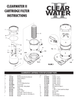
CARTRIDGE STANDARD SYSTEM
OWNER’S MANUAL
CLEAR
WATER

Our ClearWater II Cartridge Filter System is shipped from Waterway
complete with everything you need right in the box. Assemble lter
system only after above-ground pool is installed. Fill pool with water.
Do not raise water level above pool return line.
The pool equipment should be located between pool skimmer and
return line. The ltration system should not be closer than 2 ft. and not
further than 5 ft. from the pool. The ClearWater II Cartridge Filter System
needs to be on a completely at surface (e.g. patio block, cement slab,
etc.). The pump will require a 110 volt/20 amp service.
WARNING: A GFCI is required. Follow national and local
building and safety codes.
Before opening shipping carton, make sure box is in the upright
position. Inside the carton, you will nd:
1. One base
2. One pump (packaged in separate box)
3. One lter
4. Two lengths of 6 ft. hose
5. One bag with ttings
WARNING! READ ALL INSTRUCTIONS AND WARNING
LABELS BEFORE OPERATING FILTER!
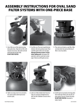
1. Place lter and base on a level, secure surface. Place the pump on
the base to the left of the lter. The pump should now be facing the
lter marked “Inlet”. There is no need to disassemble lter or pump
assemblies.
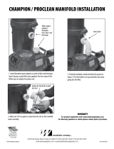
2. Open pump trap lid and remove 2" gasket. Place 2" gasket into union
nut. Hand tighten union nut to suction side of pump (Detail 5).
3. Secure pump to the base using the pin & anchor assemblies
(Detail 4).
4. Open ttings bag and remove coupling assembly (Detail 2).
Assemble 2" gasket, coupling, coupling O-Ring, and 2" union nut,
and thread into inlet side of lter.
5. Thread 2" union nut to pump discharge (Detail 3). Thread hose
adapter with O-Ring, to pump trap suction side (Detail 1).
6. From the ttings package, remove 1½" hose adapter and O-ring
(Detail 2). Thread into the outlet side of the lter tank.
7. Remove 4 hose clamps from the ttings bag. Select one of the hose
lengths and slip one clamp over the end of hose adapter. Place the
end of the hose on to the hose adapter (pump suction) and the other
end to the hose adapter end of the pool skimmer. Repeat steps with
lter outlet to pool return.
8. Remove the Lid Handle (#4a) from the ttings bag and attach it to
the top of the Lid Assembly (#4) as shown (Detail 6). Secure
ClearWater Filter to ClearWater Filter Base using #16a Phillips Head
Screws (2) (Detail 7 & 8). Fill pool until water level is halfway up
length of skimmer throat.
9. Open air release knob. Stand clear from the lter before starting the
pump. Plug in and turn on pump. Air will pass out of the lter
through the air release knob. Return to lter to close the air release
knob only when a steady stream of water (not air or air and water
mix) is discharged.
NOTE: To remove Lid Assembly, take o Filter Nut (#6) insert Filter
Wrench (#9a) in notch between Filter Body (#9) and Lid Assembly
(#4) twist and separate as shown in Detail 7.
CLEARWATER II CARTRIDGE FILTER SYSTEM OWNER’S MANUAL
INSTALLATION INSTRUCTIONS
DETAIL 1 DETAIL 2 DETAIL 3
20
21
19
22
11
10 9
14
11
15
16
10
11
12
12a
17
16 15
11 14

6
6a
6a
5
4a 4b
2
3
111
1a 1b
4
7
8
9
10
11
12
12a
13
13a (2)
18
17
18
19
22
11
10
16 15
11 14
20
21
CLEARWATER II CARTRIDGE FILTER SYSTEM REPLACEMENT PARTS
Item Part No. Description
1 830-4000SS Pressure Gauge
1a 519-7431 Fitting Adapter - Pressure Gauge
1b 805-0117SD O-Ring
2 602-0201 Air Relief Plug
3 805-0207 O-Ring - Air Relief
4 511-7327 Lid Assembly - Small (75/100 sq. ft.)
511-7337 Lid Assembly - Large (150/200 sq. ft.)
4a 519-7601 Lid Handle
4b 819-9002 #12 x ¾" S/S Phillips Head Screw
5 805-0460 Lid O-Ring
6 718-7251 Filter Nut (sold with Lid Assembly only)
6a 519-7451 Handle Assembly (2)
7 519-7441 Wing Nut
8 817-0075P Cartridge - 75 sq. ft.
817-0100P Cartridge - 100 sq. ft.
817-0150N Cartridge - 150 sq. ft.
817-0200N Cartridge - 200 sq. ft.
9 515-7257 Body - Filter Bottom
9a 519-7470 Filter Wrench (see Detail 7)
10 417-6240 1 ½" MPT x 1 ½" Male Smooth Hose Adapter
11 805-0224 O-Ring
12 500-5300 Drain Assembly
12a 505-2030 Drain Cap
13 672-7401 ClearWater II Base
13a 819-0004 #10 x 1" S/S Phillips-head Screw
14 415-5001 2" Union Nut
15 419-7241 Coupling
16 711-4010 2" Union Gasket
17 SD-07-1-T-SH HP 1.0 SPL - 1-Speed - Hi-Flo II Pump
SD-07-1-N-SH HP 1.0 SPL - 1-Speed - Hi-Flo II Pump
SD-10-1-T-SH HP 1.5 SPL - 1-Speed - Hi-Flo II Pump
SD-10-1-N-SH HP 1.5 SPL - 1-Speed - Hi-Flo II Pump
SD-10-2-T-SH HP 1.5 SPL - 2-Speed - Hi-Flo II Pump
SD-10-2-N-SH HP 1.5 SPL - 2-Speed - Hi-Flo II Pump
18 429-7221 Pin & Anchor Assembly
19 310-6500 6" Trap - 1 ½" Buttress x 2" Flange
20 319-4100 2-Piece 6" Pump Trap Lid Assembly
21 805-0436 O-Ring
22 319-3230 6" Basket Assembly
DETAIL 4 DETAIL 8
DETAIL 5
DETAIL 7
DETAIL 6
18
18
10
11 22
19
17
16
21
20
4a
4b
6
4
9
13a
13a
9a
13a

If the pressure gauge on your lter reads 5 PSI or higher than the
original starting pressure, the lter needs to be cleaned. The ClearWater
II Cartridge Filter System features the exclusive 1-2-3 Safety Locking
System to ensure safe and simple lter maintenance.
1. Turn o pump. WARNING: Never attempt to clean lter while
pump is running. This is a pressurized vessel. It could cause
severe injury or harm to your person. Plug skimmer and pool
return lines or drain pool water level to below pool return line.
2. Slowly open the air release knob on top of lter until the pressure
gauge reads “0”. Open drain cap at bottom of lter and allow water
to ow.
3. Press the yellow safety latch on the underside of the locking nut and
turn the nut counterclockwise to remove the lid. Rinse the cartridge
element with a garden hose. There is no need to remove the element
from the lter.
4. Reassemble lid and follow start-up procedures from original
instructions.
My Original Starting Pressure is ________ PSI (Pounds per
Square Inch). I should clean the lter at ________ PSI.
CLEANING INSTRUCTIONS
WARRANTY
For product registration visit: www.waterwayplastics.com.
For Warranty questions or claims please contact point of purchase.
810-0076.0522
©2022 Waterway Plastics
2200 East Sturgis Road, Oxnard CA 93030 • Phone 805.981.0262 • Fax 805.981.9403
www.waterwayplastics.com • waterway@waterwayplastics.com
Designed,
Engineered &
Manufactured
in the USA.
/