Page is loading ...

850-E Capitolio Way, San Luis Obispo, Ca 93401 • 805-549-9724 • Fax: 805-549-0306 • E-mail: [email protected] • www.cwtozone.com
Copyright © 2005 - ClearWater Tech, LLC. • Reproduction of any kind is prohibited • LIT520 • REV 062005
ClearWater Tech, LLC
Integrated Ozone Systems
Installation & Maintenance Manual
CD-2000
Corona Discharge Ozone Generators
Ozone Systems

2
This Installation and Operation Manual is written to assist in the installation, operation and
maintenance of ozone delivery systems manufactured by ClearWater Tech, LLC. The
equipment has been designed using the most modern materials and technology available.
Please read this manual carefully and in its entirety before proceeding with any installation,
operation or maintenance procedure associated with this equipment. Failure to follow these
instructions could result in personal injury, damage to the equipment or reduced
product performance.
In an ongoing effort to improve reliability and operating efciency, ClearWater Tech may nd it
necessary to make changes to its products. Therefore, the information contained in this manual
may not conform in every respect to earlier versions of ClearWaterTech ozone systems found
in the eld. If you have any questions, please contact your ClearWater Tech dealer or the
ClearWater Tech service department.
Introduction .............................................................................................................................
3
O

3
Molecular weight: 48
Odor:
Readily detectable at concentrations above 0.02 ppm in air
Color:
Bluish in ozone generator cell, but ozone/air mixture exiting
generator is invisible – even at high ozone concentrations.
Gas Density:
2.144 grams/liter at 32°F (approx. 150% that of oxygen).
Solubility:
Only partially soluble in water, but about 10-20 times more
soluble than oxygen (at 68°F).
• Ozone is generated on site – no transportation or storage is required.
• The most powerful oxidizer commercially available – very effective for
disinfection and oxidation without handling problems.
• Ozone creates no potentially harmful by-products (such as THMs) – the only
by-product is oxygen.
• Ozone leaves no telltale taste or odor.
References
1. Water Quality Association, “Ozone for POU, POE and Small Water System Water Treatment Applications,” Lisle, IL, 1999.
H
Ozone is generated by exposing oxygen molecules
(O2) in an air stream to a controlled, high energy
electrical eld. As the air stream passes through the
electrical eld produced inside the ozone
generator, some oxygen molecules are split, forming
single oxygen atoms (O1). These oxygen atoms then
recombine with other O2 molecules in the air stream,
forming ozone (O3).
Ozone is the most powerful oxidizer available that can be safely used in water treatment.1 It is used to treat
drinking water, bottled water, swimming pool water, wastewater, food and beverage processing water, and in
many other applications. Ozone is effective in performing the following water treatment functions:
O1
O2O3
Electrical Field
Oxygen (O2)
O1
O2
O3
• Disinfection – Bacterial disinfection,
inactivation of viruses and cysts.
• Oxidation of Inorganics – Precipitates iron,
manganese, suldes, nitrites and organically-
bound heavy metals.
• Oxidation of Organics – Including organics
causing color, taste and odor problems, some
detergents and pesticides, phenols, VOCs,
turbidity control and microocculation of soluble
organics.
Ozone (O3)

4
ClearWater Tech ozone systems are designed for safe, effective use in a variety of water treatment
applications. Each complete, integrated system includes the components required for reliable,
efcient ozone production and can be divided into four general segments:
• Air preparation system • Ozone generator • Ozone injection/contacting • Ozone destruct
Shown: ClearWater Tech CD4000P Ozone System
Ozone Generator
Water Flow
Booster Pump
Vacuum Break
Contact Vessel
Water Trap
Ozone
Destruct
Unit
Ball Valve
Ozone Injector
Air Preparation System
CD4000P
ClearWater Tech commercial cabinet ozone generators require a source of clean, dry, oxygen-enriched air for
effective ozone production. To meet that need, the rack-mount air preparation systems built by ClearWater
Tech employ pressure swing adsorption (PSA) technology to increase the concentration of oxygen and reduce
the moisture content in the feed gas (the air supplied to the ozone generator). This substantially improves the
output capability of the ozone generator and prevents premature failure of key internal components. These air
preparation systems deliver 90%+/-3% oxygen purity at -100°F dew point and at very low pneumatic
pressures, minimizing noise and reducing compressor wear.
If “Plant Air” feed gas is to be used, in place of the ClearWater Tech air preparation system, the same air
quality standards must be met to achieve the ozone output and longevity of the ozone generator. A PSI
(pounds per square inch) regulator must be installed when using plant air feed gas. The regulator must be
set to a maximum of 10 PSI.

5
Theory of Operation/Product Description (continued)
ClearWater Tech pressurized ozone generators are designed to supply high concentrations of ozone gas (up to
10%) at 10 PSI. The oxygen feed gas produced by the air preparation system is supplied to the ozone
generator, which ows through a built-in ow meter. A stainless steel needle valve (preset inside the ozone
generator), located on the stainless steel delivery line, is used to maintain optimum pneumatic parameters
inside the reaction chambers. After this point the vacuum created at the ozone injector draws the ozone gas
into the water line. The ozone generator is equipped with a pressure switch, which prevents its operation of the
system if the pressure within the reaction chambers drops below 9 PSI.
As the feed gas enters the fused, thermally-protected reaction chambers inside the ozone generator, some of
the oxygen molecules are split while passing through the high voltage electrical eld (the “corona”), forming
single oxygen atoms (O1). These oxygen atoms then recombine with other oxygen molecules in the air stream,
forming ozone. The modular, multiple reaction chamber design allows the ozone generator to keep working
even if one or more of the chambers requires service.
Depending on the application, the ClearWater Tech ozone generator may be interlocked with an ORP controller,
pressure switch, timer or circulation pump. The CD4000P is equipped with two three-way solenoid valves. While
the valve on the right (closest to the cabinet wall) is for additional back ow prevention, the valve to the left is to
depressurize and “off gas” residual ozone from the ozone reaction chambers. An internal off gas destruct
(mounted inside the ozone generator) is used to destroy this residual ozone, (see Appendix - Section B).
Other safety features are also built in, including a pressure switch and thermal protection.
The ozone injector serves two purposes: One, it creates the vacuum required to safely draw the ozone gas
from the ozone generator and two, it provides a means by which the ozone gas can become dissolved in water.
A very dynamic injection process is required to effectively dissolve ozone in water.
ClearWater Tech injection systems use only Mazzei® injectors for maximum mass transfer efciency. The
injector produces a cavitation effect, enabling the ozone gas to join the water stream in the form of extremely
tiny bubbles. These bubbles must be as small as possible in order to increase the ratio of bubble surface area
to the amount of ozone entering the water.
Depending on the application and the water treatment goals, a ClearWater Tech contacting system may also
be required. Some oxidation reactions take place so quickly that they are limited only by the rate at which the
ozone is dissolved in the water. Other reactions, such as disinfection, may require that a proper ozone residual
be maintained for a specic amount of time. A correctly-sized contact vessel is used for this purpose.
The ClearWater Tech off-gas destruct systems consists of two components - the ozone destruct unit (a heated
chamber lled with manganese dioxide and copper oxide) and a water trap. Used in conjunction with a ClearWater
Tech off gas vent, the ozone destruct system is an effective way to vent the contact vessel(s) when it is impractical
to send the off gas to atmosphere or reintroduce it to the water.
LESSON 1 - The large bubble (20mm) has
a volume of 4.19 cm3 and a surface area of
12.6 cm2.
LESSON 2 - 296 small bubbles (3mm) could be
made from the large bubble in lesson 1. They would
have a total surface area of 83.6 cm2. This is 6.6
times the surface area of the large bubble.
LESSON 3 - Theoretically, 6.6 times as
much water could be ozonated with the same
amount of ozone!

6
Two aspects of ClearWater Tech ozone generators represent potential dangers – ozone gas and high
voltage electricity.
- WARNING: HIGH CONCENTRATIONS OF OZONE GAS ARE DANGEROUS
TO HUMANS. LOW CONCENTRATIONS CAN CAUSE IRRITATION TO
THE EYES, THROAT AND RESPIRATORY SYSTEM.
- WARNING: CLEARWATER TECH OZONE GENERATORS OPERATE
AT HIGH VOLTAGES. DO NOT TAMPER WITH OR DELIBERATELY
BYPASS THE DOOR OR SAFETY SWITCHES BUILT INTO THE
OZONE GENERATOR UNLESS INSTRUCTED TO DO SO BY THIS
MANUAL. IF CONTACT IS MADE WITH OPERATING HIGH
VOLTAGE COMPONENTS, ELECTRIC SHOCK WILL OCCUR.
ClearWater Tech corona discharge ozone generators take line voltage and convert it to 48 VDC. A high
voltage transformer then boosts the voltage. While each ozone generator has a door switch and other
safety interlocks, proper care must be used by a qualied electrician when making any internal
adjustments or performing any maintenance procedures.
This ClearWater Tech corona discharge
ozone generator is designed to operate under
a pressure condition. While safety precautions
have been taken, entering the equipment area
should be avoided if ozone gas is detected.
Ozone has a very distinctive odor and is de-
tectable at very low concentrations (0.02 ppm),
which is far below OSHA’s maximum permissible
exposure level of 0.1 ppm.

7
When installing and using this
electrical equipment, basic safety precautions should always be followed, including the following:
1. READ AND FOLLOW ALL INSTRUCTIONS.
2. SAVE THESE INSTRUCTIONS.
3. Allelectricalconnectionsshouldbemadebyalicensed,qualiedelectrician.
4. Before attempting any electrical connections, be sure all power is off at the main circuit breaker.
5. Installallelectricalequipmentatleastvefeetfromanyopenbodyofwaterusingnon-metallicplumbing.
6. Installcheckvalvesandavacuumbreaktopreventwaterfromcontactingtheelectricalequipment.
7. Theelectricalsupplyforthisproductmustincludeasuitably-ratedswitchorcircuitbreakertoopenall
ungroundedsupplyconductorstocomplywithSection422-20oftheNationalElectricalCode,ANSI/NFPA
70-1987.Thedisconnectingmeansmustbereadilyaccessibletotheoperator(s)butinstalledatleastve
feet from any open body of water.
8. Besuretobond(ground)thesystemusingthecopperbondinglugonthebottomoftheozonegenerator.The
system should be bonded with solid copper wire conforming with all local, state and national electrical codes.
9. Thesystemshouldbesizedappropriatelyforitsintendedusebyaqualiedprofessionalfamiliarwiththe
application.Thisequipmentmustbevalidatedbythemanufacturerforitsintendeduse.
Safety Information (continued)

8
Compare the ozone system equipment received to the packing list provided.
Before beginning any installation procedures, thoroughly inspect all
components for damage. If damage is noticed, promptly notify the freight
carrier and request an on-site inspection. Inspect all packing materials for small
parts before discarding. Inspect all plumbing, ttings and tubing for packing
material that may have become lodged in openings.
• When placing the ozone system components in the equipment room, make sure to consider safety,
maintenance requirements, local building and re codes, etc. The components should be easily
accessible by the operators, including equipment access doors and electrical hook-up boxes. All
meters, gauges, indicator lights and switches should be visible and accessible. Dimensional drawings
of each air preparation system and ozone generator are included in Section A of the Appendix.
• The air preparation system and ozone generator should be located as close as possible to the point
of ozone injection. Ozone is an unstable gas and will begin reverting back to oxygen very quickly.
To determine the most favorable ozone injection point, the following items should be considered:
• Located downstream of all other existing water system components.
• Located upstream of the residual sanitizer injection point (if so equipped).
• In a Sidestream plumbing conguration (see Figure 5-1) with recirculation, the pH adjustment
chemical injection point must be located downstream of the residual sanitizer injection point
(if so equipped).
• In a Full Flow plumbing conguration (see Figure 5-2) without recirculation, locate
downstream of the pH adjustment chemical injection point
• Adequate protection from weather, dust and excessive heat.
• Like any electronic component, performance and longevity is enhanced by favorable operating
conditions. Also, since each air preparation system and ozone generator is air-cooled, a relatively
dust-free, well ventilated area is required. No caustic chemicals should be stored in the area
surrounding the equipment. A minimum clearance of six inches from the vents on either side of the
ozone generator is required.
• The equipment is heavy and requires proper support. Therefore, a clean, dry, level surface should be
provided for the air preparation system and ozone generator. These components should be securely
fastened to the surface using the mounting holes and/or tabs provided.
• The air preparation system and ozone generator are not designed to withstand outdoor elements,
including direct contact with water and/or temperature extremes. Therefore, the equipment must be
installed in an environment consistent with the following operating parameters:
• Ambient temperature range: 20°F to 85°F continuous. If the temperature around the
equipment
consistently exceeds 85°F, additional air cooling must be provided.
• Humidity: 0 – 90% relative humidity, non-condensing environment
• Line voltage: +/-10% of rated input
Note: Equipment installed in extreme environmental conditions will void manufacturer's warranty.
• Allow room for the peripheral equipment (booster pump, injector manifold, contact vessel, etc.).
Getting Started

9
CORONA DISCHARGE (CD) OZONE SYSTEMS
Ozone is manufactured in the CD ozone generator by drawing in air, which is composed of 20% oxygen
(O2), and exposing it to multiple high voltage electrical discharges. This causes a percentage of the oxygen
molecules to dissociate and reassemble as ozone (O3). The corona discharge method is the most efcient
way to produce large amounts of ozone.
3 - O2 2 - O3
Chemical Formula (simplied)
for Corona Discharge Ozone
In contrast to ultraviolet ozone generators, corona discharge systems produce a much higher concentration
of ozone and in much larger quantities. In addition, the annual expense of replacing lamps and checking
ballasts is unnecessary with corona discharge systems. Corona discharge ozone generation is the most
economical and effective method to use on most water treatment applications.
ClearWater Tech manufactures high output corona discharge systems capable of producing enough ozone
to oxidize iron, sulde, manganese and act as an efcient sanitizer in a variety of applications. Ozone
reacts to water-borne contaminants signicantly faster than other disinfectants and the primary by-product
is pure oxygen.
ClearWater Tech ozone systems are built with the nest components available. All are air cooled and are
most efcient when used with a venturi injection system to create the best possible contact and mixing of
ozone while maintaining a high level of safety.
UNCRATING and INSPECTION
Shipping Terms
Unless special arrangements have been made, the ozone equipment will be shipped FOB ClearWater
Tech's factory in San Luis Obispo, CA. The freight charges will be prepaid and billed or shipped freight
collect. Transfer of liability to the freight company and the customer occurs as the equipment leaves the
factory loading dock and is accepted by the freight line.
Freight Inspection
All equipment should be thoroughly inspected immediately upon delivery. If any damage is noticed,
promptly notify the freight line and request an on-site inspection.
Unpacking
Typically, the equipment will arrive on a pallet. Compare the components with the packing list. Thoroughly
inspect all packing materials prior to discarding. Inspect all plumbing ttings and tubing for packing mate-
rial inadvertently lodged in any openings.
Placement of Equipment
Select a location for the ozone equipment that is as close as possible to the ozone injection point. Arrange
the components (ozone generator, air dryer and electrical interlock box, if so equipped) in a manner suitable
for convenient electrical access. The system component enclosures are not rain proof, so it is important to
choose a location that will keep the system away from direct weather and excessive heat.
Mounting holes are located on the back of all components for convenient wall mounting. Mounting hardware
is not provided.
ClearWater Tech air preparation and ozone generation systems Models M-1500 and P-2000 are a vacuum type and
will require adjustment of the air ow through the system. On the front of the electrical interlock box is a VAC/PSI
Installation Procedures (continued)

10
Materials
Use Schedule 80 PVC for all plumbing connections whenever possible. Also, it is recommended that unions and
valves are used wherever practical. Ozone rapidly deteriorates a variety of compounds; the following is a list of
materials that may be used . . .
. . . with ozone in gaseous phase (at high concentrations):
Viton Teon® Stainless Steel EPDM
Silicon Kynar® Hepalon
. . . with ozone in aqueous phase (at low concentrations):
Viton Teon® Stainless Steel EPDM
Silicon Kynar® Concrete Hepalon
Schedule 40 PVC Schedule 80 PVC
NOTE: Be sure to use good plumbing practices and install unions and isolation valves wherever the situation
dictates, i.e. pump or injector removal, etc. Secure all plumbing with unistrut or similar hardware.
Tubing Installation
1. Install braided tubing from the indicating desiccant chamber on the air dryer to the brass AIR INLET tting
on the bottom of the ozone generator (or the bottom of the electrical interlock box if so equipped). If you
are not using an electrical interlock box, skip Step 2 and go to Step 3.
2. If equipped with the electrical interlock box, continue running the braided tubing from the electrical interlock
box brass AIR OUTLET tting to the brass barb AIR INLET tting on the bottom of the ozone generator.
3. Install the ozone check valve assembly onto the injector. Connect the 1/4” Teon® tubing from the Teon®
OZONE OUT compression tting on the bottom of the ozone generator to the Teon® compression t-
ting on the check valve assembly on the injector. Secure by tightening the tting around the 1/4” Teon®
tubing after insertion. (If equipped with the electrical interlock box, install the 1/4” Teon® tubing from the
OZONE OUT tting on the bottom of the ozone generator to the stainless steel solenoid valve located
on the top of the electrical interlock box. Continue running the Teon® line from the solenoid valve to the
check valve assembly on the injector.)
Check Valve Selection
The ozone check valve is an important component in preventing damage to the ozone generator. All ClearWater
Tech CD2000 ozone generator is equipped with a Kynar® low pressure check valve on the ozone outlet. A second
check valve should be installed on the venturi injector ozone inlet. This check valve should be matched to the
application. A low pressure Kynar® check valve is appropriate for applications where the system pressure will not
exceed 40 psi. Higher line or system pressure installations require a stainless steel check valve.
Note: The cracking pressure (the pressure at which the valve opens) of any stainless steel or Kynar® check valves
not sourced through ClearWater Tech must not exceed 0.5 lb. (0.33 lb. is recommended.
Installation Procedures (continued)

11
Ozone Generator
The ozone generator houses the ozone reaction chamber(s), power supply and all electrical components directly related
to the production of ozone. Ozone is produced when the feed gas is exposed to a high voltage electrical current inside
the reaction chamber.
Air Preparation
The ClearWater Tech ozone system may be equipped with a heat regenerative desiccant air dryer. Corona discharge
ozone generators are much more effective, produce more ozone and require far less maintenance if an air preparation
unit is included. The air preparation system lowers the dew point of the feed gas. Moist feed gas (air) will cause nitric
acid to form inside the generator which decreases ozone production and if not removed, causes corrosion and eventual
failure of the generator’s internal components. The ability of the ozone generator to produce ozone is drastically reduced
as the dew point rises above -60°C.
Injector Manifold
The ozone gas is injected into the ltered water return line by means of the injector manifold. This allows the ozone to be
injected into the water under a vacuum condition which is the safest technology available.
Contact Vessel (optional)
To maximize the effectiveness of ozone, it must be thoroughly mixed and have adequate time to react with the
contaminants in the water before being ltered or utilized. Contact vessels are designed to achieve this necessary
mixing and contact time. ClearWater Tech supplies several different types of contact vessels for a variety of applications.
Booster Pump (optional)
If excessive back pressure is created in the water line by lters, pressure tanks or other system parameters, a booster
pump may be necessary to create a sufcient pressure differential across the venturi. This booster pump is used in con-
junction with a side stream ozone injection loop.
Electrical Interlock Box (optional)
The electrical interlock box is a multi-function electrical enclosure. It houses the Motor Control Interlock (MCI), ORP
Interlock and the Vacuum Interlock. The enclosure also acts as the air preparation monitoring station, controlling the
amount of intake air and monitoring the vacuum.

12
Full Flow Plumbing Connections
Refertothe‘FullFlowInstallation’diagramonthenextpageandfollowtheinstructionsbelowiftheozoneisbeinginjected
directlyintothefullowofthepool’sreturnline:
1.Tapintothereturnlineafterthepump,lter,andheater.Theozoneinjectionpointshouldbethelastcomponentinlineand
asfaraspossiblefromtheresidualsanitizerinjectionpoint.
2. Glueintheproperinjector,notingthedirectionofow(indicatedbyanarrowontheinjector).
3.Oncetheinjectorisinstalled,thevacuummaybeadjustedasdescribedinthe“ozonegeneratoroperation”section.Ifthe
systemisequippedwiththeoptionalelectricalinterlockbox,thevacuumcanbeobservedontheVAC/PSIgaugelocated
abovetheSCFHgaugeontheelectricalinterlockbox.
Note: The ozone generator will only energize for 15 seconds or until a vacuum is attained.
Tubing Installation
1.InstallbraidedtubingfromtheairdryertotheAIRINLETttingonthebottomoftheozonegenerator(orthebottomofthe
electricalinterlockboxifsoequipped).Ifyouarenotusinganelectricalinterlockbox,skipStep2andgotoStep3.
2.Ifequippedwiththeelectricalinterlockbox,continuerunningthebraidedtubingfromtheelectricalinterlockboxtothe
brassbarbttingonthebottomoftheozonegenerator.
3.Installthecheckvalveassemblyintotheinjector.Connectthe1/4”Teon®tubingfromtheOZONEOUTttingonthe
bottomoftheozonegeneratortothecheckvalveassemblyontheinjector.Securebytighteningthettingaroundthe
1/4”Teon®tubingafterinsertion.(Ifequippedwiththeelectricalinterlockbox,installthe1/4”Teon® tubing from
theOZONEOUTttingonthebottomoftheozone generatortothestainlesssteelsolenoidvalvelocatedonthetopofthe
electricalinterlockbox.ContinuerunningtheTeon®linefromthesolenoidvalvetothecheckvalveassemblyonthe
injector.
Independent Ozone Loop Plumbing Connections
Refertodiagrams(pgs7-8)andfollowtheinstructionsbelowiftheozoneisbeinginjectedintoanindependentozoneloop.
Ifcircumstancesallow(newconstruction,pre-plumbedforanozoneloop),theidealcongurationisfortheozonelooptobecom-
pletelyindependentfromthepool’scirculationsystem.Otherwise,thefeedwaterforthesidestreamispulledfromthemainreturn
before the circulation pump and returned at a point afterthelterandheater.Thisisdonesotheboosterpumpisnotattemptingto
drawwaterthroughthelterandfromthecirculationpumpwhenthecirculationpumpisnotoperating.ThepHadjustmentpoint
will always be the last item in this sequence.
UseSchedule80PVCforplumbingconnectionswhenpossible.Itisrecommendedthatunionsandvalvesareusedwherepractical.
Ozone rapidly deteriorates many compounds; the following is a list of materials that may be used with ozone in an
aqueous solution.
VitonTeon®Sch.40PVCStainlessSteel EPDM
Silicon Kynar Sch.80PVCConcrete Hepalon
NOTE: Be sure to use good plumbing practices and install unions and isolation valves wherever the situation dictates,
i.e. pump removal, etc. Secure all plumbing with unistrut or similar hardware.
1. Inthemainwaterreturnline,beforethecirculationpump(orapre-plumbedindependentsuctionttingifnewconstruction)
installateeandanisolationvalve.
2. Install the booster pump. Secure the pump on a housekeeping pad with the appropriate mounting hardware.
3. Ifanauxiliarycontrolrelay(i.e.owswitch)isbeingused,installitintothelineaftertheozoneboosterpump.
4. Installtheinjectormanifoldaftertheozoneboosterpump,makingsuretonotethecorrectowdirectionoftheinjector
manifold.Removethetiewrapsthatsecurethecheckvalveassemblytotheinjectormanifoldandthreadthecheck
valveassemblyontotheopeningoftheventuri.

13

14

15

16
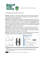
OPTIONAL VACUUM BREAK INSTALLATION
Location
Selectasuitableverticalsurfacethatisaccessibleandincloseproximitytotheozonegeneratorandventurimanifoldonwhichto
mountthevacuumbreak.
Installation Steps
1. InstallthetwomountingClic®clampsprovidedontheverticalsurfacesothatthevacuumbreakwillbeinaverticalpositionand
theheightofthell/drainvalvettingwillbebelowtheleveloftheozonegeneratorbulkheadcheckvalve.Oneclampshould
belocateddirectlyabovethevacuumbreak’sbottomendcapandtheotherjustbelowthell/drainttingtee.
2. Installthetworeducerbushingsprovidedintotherisertee,oneintothesidetappingandtheotherintothetoptapping.
Besuretouse2-3wrapsofTeon® tape on the male threads.
3. InstallthePVCballvalveprovidedintothereducerbushinginthesidetappingontherisertee.Besuretouse2-3wrapsof
Teon®tapeonthemalethreads.Thisvalvecontrolstheamountofwaterthatisdrawnupintotherisertubebythesuction
oftheventuri.Itcanalsobeusedtoisolatetheventurishouldacheckvalvefail.
4. Installthe90ºKynar®ttingprovidedintothereducerbushingonthetoptappingontherisertee.Besuretouse2-3
wrapsofTeon® tape on the male threads.
5. Placethetwo-inchdiameterwaterreservoirintothemountingClic®clampsandsecure.Checktomakesuretheheightofthe
ll/drainttingisbelowtheleveloftheozonegeneratorbulkheadcheckvalve.
6.Slidetherisertubeintothewaterreservoir.
7. Attachoneendofasuitablelengthof1/4”Teon®tubingprovidedtothe90ºKynar® compressionttingonthetopof
therisertee.Attachtheotherendofthetubingtothebulkheadcheckvalveonthebottomoftheozonegenerator.The
lengthofthetubingwilldependonthedistancebetweenthevacuumbreakandtheozonegenerator.
8. Initiatewaterowthroughthesystem(e.g.,startthecirculationpumporboosterpump)sowaterisowingthroughthe
venturiinjector.Adjustthesuctionattheventuriwithahand-heldSCFHgauge,matchingtheairowtothecorrect
specicationasoutlinedonpages17and18.
9. ClosethePVCballvalveontherisertee.Usingthestraightcompressionttingprovided,attachanothersuitablelength
of1/4”Teon®tubingtotheoutletofthePVCballvalve.Attachtheotherendofthetubingtothecompressionttingonthe
venturicheckvalveassembly.
10. Turnthell/drainttingsotheopeningfacesupwardandaddwatertothewaterreservoiruntilitbeginstooverowoutofthe
ll/draintting.Nowturnthettingsotheopeningfacesdownward.
11. SlowlyopenthePVCballvalveontherisertee,allowingthewaterlevelintherisertubetorisetoalevelnocloserthantwo
inches from the bottom of the riser tee.
12.Connectasuitablelengthofthe3/4”braidedtubingprovidedtothebarbedttingonthell/draintting.Makesure
theopenendofthetubinggoestosafe,properdrainageandthatthetubehasnoowrestrictions.
13.Runthesystemtoensurethewaterlevelintherisertubeisstabilized.
Note:Theproperwaterlevelmustbemaintainedinthewaterreservoir.Whenfull,thereservoircontainsabouttwicetheamount
ofwaterrequiredtolltherisertube,soitmustalwaysbekeptatleasthalffull.Aninsufcientwaterlevelwillresultinalossof
vacuum,preventingairowthroughtheozonegenerator.
Plumbing Connections - continued

17
Plumbing Connections - continued
Ozone Generator
Ozone Flow
Fill Port Cap
Upper Tee
Lower Tee
Ozone Flow
Check Valve Assembly
Ozone Injector Manifold
Venturi
Drain Port
Flapper
Valve
Riser Tube
Elbow
Mounting Clamps

18
OPTIONAL CONTACT COLUMN INSTALLATION
Location
The contact column(s) should be installed after the injector manifold(s), within three (3) feet of a wall or solid mounting
surface using isolation valves to facilitate cleaning the diffuser, if needed. There should be as few elbows as possible
between the injector(s) and the contact column(s). Be sure to note the ow direction of the column(s).
Mounting To a Wall or Other Solid Mounting Surface Using the Hardware Kit
Refer to the diagrams on the next pages and follow these instructions:
1. Locate the following items from the hardware kit:
• ‘L’ bracket
• two 1/2” concrete anchors with nuts and washers
• unistrut and protective end cap
• 6” clamp assembly with nut and bolt
2. Mark the two holes for the ‘L’ bracket on the wall. The ‘L’ bracket should be in located above the center of the length
of the contact column. A foot or so from the top is ideal. Drill two 1/2” holes where you marked, about 31/2” to 4”
deep. Insert one concrete anchor into each hole with the threaded end sticking out. Slip the ‘L’ bracket over these
threaded ends and tighten down with the nuts and washers provided. This will cause the ends of the concrete
anchors in the wall to expand and thus secure the ‘L’ bracket to the wall.
3. Bolt the unistrut to the ‘L’ bracket with two bolts, nuts and washers. NOTE: The unistrut may be cut to length if
desired.
4. Slip the two 6” clamp pieces into the unistrut around the contact column. Tighten bolt.
5. Attach the protective end cap to the exposed end of the unistrut.
Plumbing Connections - continued

19
MOUNTING CONTACT COLUMN TO WALL USING UNISTRUT MOUNTING SYSTEM
MOUNTING TWO CONTACT COLUMNS TO WALL USING UNISTRUT MOUNTING SYSTEM
6' Clamp Assembly
with Bolt & Nut
Unistrut (may get cut
to length desired)
Unistrut
Protective
End Cap
Contact Column
Concrete Anchors with
Nuts & Washers (2 each)
"L" Bracket
Bolts, Nuts & Washers
(2 each)
1/2" Holes Drilled Into
Wall (3 .5" to 4" deep)
Wall
6' Clamp Assemblies
(2)with Bolt & Nut
Unistrut (may get cut
to length desired)
Unistrut
Protective
End Cap
Contact Columns
1/2" Holes Drilled Into
Wall (3 .5" to 4" deep)
Bolts, Nuts & Washers
(2 each)
Concrete Anchors with
Nuts & Washers (2 each)
"L" Bracket
Wall

20
Installation of Contact Column Vent Line
1. Drillandtapa1/4”MPTholeintothemainwaterreturnline
after the heater. This hole should be drilled into a location with
less pressure than the ozone loop so that the contact column
will continually bleed ozone gas buildup on top of the column
tobemixedbackintothemainwaterline.(Donotinstallthis
ventlineonthesuctionsideofthepump.)
2. Install the Teon® vent line from the Kynar® tting on the
top of the contact column to the location drilled into the main
water line.
Vent Line Installation Detail
Compression
Elbow Fitting
Contact
Column
Needle Valve
(may be installed
anywhere along
vent line)
Vent Line
Compression Fitting
Water Return Line
/