Page is loading ...


Congratulations on your choice of a Stratford Stove.
More than 20 years experience has been put into the
development of our Stratford family to ensure ultimate
performance and years of trouble free use and enjoyment
Every detail of the fire has been carefully designed and
engineered which is why we are so confident in the reliability
of our products
Should you have any questions about our Stratford Stoves
that are not covered buy our manual set, please contact the
Stratford dealer in your area, or call our technical support
department on 01308 427234
Copyright 2008
Arada Ltd
This booklet has copyright and may not be
copied in whole or part, or used for any
purpose other than that for which it is supplied
without express written consent form.
Stratford EcoBoiler Stove 2

Contents
Stratford EcoBoiler Stove
Page No.
INTRODUCTION
Important fuel notice 4
Safety Notice 5
The Principle of the Fire 5
Check List A: ( Stove Body ) 6
Check List B: ( Canopy ) 7
Technical Data / Data Plate 8
INSTALLATION
General Precautions 9
Handling 9
Hearth 9
Combustable materials 9
Air For Combustion 9
Multi Fuel grate and grate bars 10
FEDS inspection & fitting 11
Fitting The Canopy 12-13
Flue outlet and Hotplate 14
Flues and Chimneys 14-17
Integral Boilers 18
Checking the Thermostat 18
Typical installation examples for boilers 19-20
Boiler tapping positions 21
Water connections 22
Hot water system check list 23
Final installation check list 24
Page No.
SERVICE & MAINTENANCE
Annual Maintenance 25
Cleaning 25
Chimney Sweeping 25
Door Glass & Outer Finish 25
Adjustment of Thermostat damper 26
Removal of Air Wash 27
Adjustment of Door Hinges 27
Fire Door Rope Replacement 28
Fire Door Glass Replacement 29
Cleaning around Thermostat Damper 30
Service Record 31
OPERATING INSTRUCTIONS
Multi Fuel grate 32
Air Inlet Controls 32
Operating Tool 33
Grate riddling 33
Fuel Types 34
Lighting the stove 34
Solid fuel & Longer burning periods 35
Over firing, Chimney fires 36
and Ash removal
Optional Extra / Accessories 37
SPARE PARTS LIST 38-40
GUARANTEE 41
ADDITIONAL NOTES 42-43
FACTORY CHECK LIST 44
3

WARNING
IT IS A LEGAL REQUIREMENT THAT THE INSTALLATION OF ALL
NEW OR REPLACEMENT, WOOD OR SOLIDFUEL HEATING
APPLIANCES ARE REQUIRED TO OBTAIN BUILDING CONTROL
APPROVAL FROM YOUR LOCAL AUTHORITY OR THE
INSTALLATION WORK MUST BE CARRIED OUT THROUGH A
GOVERNMENT APPROVED COMPETENT PERSONS SCHEME
SUCH AS OPERATED BY HETAS.
IF IN DOUBT, CONTACT HETAS LIMITED
TELEPHONE NUMBER : 0845 634 5626
www.hetas.co.uk
THIS STOVE MUST NOT BE CONNECTED
TO A SHARED FLUE SYSTEM
TO ALL USERS
PETROLEUM COKE
SOME OF WHOSE BRAND NAMES ARE
‘CALCO’, ‘PETROCOKE’ AND ‘WONDERCO’
MUST NOT BE BURNED IN THIS APPLIANCE
BITUMINOUS HOUSE COAL
SHOULD NEVER BE USED IN YOUR STOVE
TO USE OTHER FUELS WILL INVALIDATE
THE APPLIANCE GUARANTEE
IF IN DOUBT CONTACT THE SOLID FUEL ASSOCIATION
TELEPHONE NUMBER 0845 601 4460
www.solidfuel.co.uk
Stratford EcoBoiler Stoves 4

SAFETY
A fireguard conforming to BS 8423:2002 should be
used in the presence of children and old or infirm
people.
Please note, this appliance should be used with
the fire door closed at all times except when fuel-
ling, de-ashing or initial lighting.
Do not use aerosol sprays or any other
flammable materials near the appliance
under fire.
Do not fit an extractor fan in the same room as
the appliance.
Fire cement is caustic, hand and eye
protection should always be worn,
prolonged contact with the skin should be
avoided.
Arada Ltd will not be responsible for any Con-
sequential or incidental loss or
Injury however caused.
Before continuing any further with the
installation of this appliance please read the
following guide to manual handling.
• Always obtain assistance when lifting the
appliance
• When lifting always keep your back straight,
bend your back not your legs
• Avoid twisting at the waist. It is better to
reposition your feet.
• Avoid upper body/top heavy bending. Do not
lean forwards or sideways when handling the
fire
• Always grip with the palms of your hands
do not use your fingertips for support
• Always keep the stove as close to the body as
possible as this will minimise the canter lever
action.
• Use gloves to provide additional grip.
• We recommend the use of lifting straps when
handling the stove as lifting by the canopy is not
possible
THE PRINCILE OF THE STOVE
Your Stratford stove is built to the highest standard
of craftsmanship using the best materials and the
most modern equipment available. It is a highly
efficient and sophisticated piece of machinery and
when properly installed and operated it should
provide a lifetime of heating satisfaction.
Safety is the most important consideration when
installing your fire. If not properly installed and
operated a house fire may result. Installation must
comply with the Building regulations and conform to
all safety standards.
Arada produce a variety of appliances ranging from
the traditional to the modern in style and
appearance, all bristling with ‘High Tech’ features.
The fire door is fitted with a special high temperature
ceramic glass panel through which the fire can be
viewed.
An internal throat plate produces turbulence to
encourage secondary combustion and direct the flue
gas around the whole upper firebox before allowing it
to escape up the chimney.
Arada stoves are also fitted with an ‘air wash’ so
called because it provides a curtain of high speed
preheated air behind the glass to help keep it clean
and provide secondary air/over draught.
The provision of two inlets on all stoves gives a wide
range of primary / secondary air, under draught /
over draught combinations. The optimum setting will
only be established by experience in firing the
appliance, and will depend on the type of fuel, the
position of the appliance in the house, conditions of
chimney etc..
Stratford EcoBoiler Stove
INTRODUCTION
5

CHECK LIST A: (Stove body )
6
Inside the appliance body you should find the following:
Part Description & Visual Aid (not to scale) Stratford
SEB15 Stratford
SEB 20 Stratford
SEB30 Stratford
SEB 40
1. Fuel retainer
1 1 1 1
2. Grate bars
9 11 13 13
3. Lower FEDS cover
1 1 1 1
4. Flue spigot
1, ( 5" 1, ( 5" ) 1, ( 6" ) 1, ( 6" )
5. Hot plate 1, ( 5" 1, ( 5" ) 1, ( 6" ) 1, ( 6" )
6. Ash pan
1 1 1 1
7. Operating tool 1 1 1 1
9. Fire door handle 3 4 4 4
10. Instruction manual
1 1 1 1
11. Top insulation mats
2 2 2 2
12. Heat resistant mitten 1 1 1 1
8. Fire bed supports 2 4 4 4
Stratford EcoBoiler Stove

CHECK LIST B: (Canopy)
The canopy option selected should comprise of the following parts:
Stratford EcoBoiler Stove
Part Description & Visual Aid (not to scale) Slab top Rolled top Raised top
1. Main canopy component
1 1 1
2. Top hot plate cover
1 1 0
3. Rear flue, Top blanking plate
0 0 1
4. Top flue, Raised canopy kit
0 0 1
7

8
TECHNICAL DATA
TECHNICAL DATA Stratford
SEB15 Stratford
SEB 20 Stratford
SEB30 Stratford
SEB 40
Total output (kW) 16 20 30 40
Output to Room / Water (kW) 6.5/ 9.5 8/12 12/18 16/24
Efficiency Gross. (%) TBA 71.5 TBA TBA
Mean Co Emission @ 13% O2 (%) TBA 0.31 TBA TBA
Flue Mass gas Flow (g/s) TBA 13.1 TBA TBA
Overall height (Stove body only ) (mm +/-3) TBA 670 TBA TBA
Overall Width (Stove body only ) (mm +/-3) TBA 565 TBA TBA
Overall depth (Stove body only ) (mm +/-3) TBA 430 TBA TBA
Height to centre of rear flue TBA 505 TBA TBA
Depth from back to centre of top flue TBA 160 TBA TBA
Flue diameter (mm / inch) 127 / 5 127 / 5 152 / 6 152 / 6
Weight packed (Kg) (stove body ONLY) TBA 127 TBA TBA
Height / Weight, Slab top (mm +/-3 / Kg) TBA / TBA 686 / 609 TBA / TBA TBA / TBA
Height / Weight, Rolled top (mm +/-3 / Kg) TBA / TBA 681 / 626 TBA / TBA TBA / TBA
Height / Weight, Raised top (mm +/-3 / Kg) TBA / TBA 777 / 625 TBA / TBA TBA / TBA
Mean Flue Gas Temperature °C TBA 403 TBA TBA
Minimum Distance to Combustible materials (mm) TBA Back-150
Side -130 TBA TBA
1 Kw = 3420 BTU, 1 inch = 25.4mm
Stratford EcoBoiler Stove
Stove Data Plate: Data Plate Location:
Arada Stove Data Plate
Information
Arada stoves are fitted with a data plate
located at the rear of the stove on the bottom
right hand side. The plate can be folded out
from its recess by pulling down on the plate’s
tag.
This should only be done when the stove us
cold and unlit. The data given is that regis-
tered on the HETAS website on the output
and performance of the stove.
The CE mark indicates that the stove
performance has been independently certified
by a competent body.

Stratford EcoBoiler Stove
GENERAL PRECAUTIONS
Note - All local regulation , including those
referring to National and European stan-
dards need to be complied with, when in-
stalling the appliance. We strongly advise
that installation should only be carried out
by a qualified Solid Fuel Heating Engineer,
covered by the HETAS scheme (see page 12)
as installation by non-qualified persons may
affect the guarantee.
The building Regulations for England and Wales
2000 ref Approved Document J 2002 edition
(issued by the DTLR). The Building Standard
(Scotland) (Consolidation) Regulations. Detailed
recommendations for installation of Appliances,
chimneys and flues are outlined in the current
issue of the following British Standards BS6461,
BS8303 and BS4543
Any manufacturer’s instruction must NOT
be taken as overriding statutory require-
ments.
During installation ensure that adequate
precautions are taken to avoid unnecessary risk
to yourself or any householder. In particular the
danger from the caustic nature of the fire
cement should be avoided by using these
accepted methods:
• Wear gloves handling fire cement
• Wear goggles when chiselling or looking
up chimneys
Make sure that Building Regulation are adhered
to during installation along with any local by-
laws. In the case of heating systems ensure that
the pipe work is correctly bonded to provide a
correct electrical earth.
HANDLING
By the time you read this you will appreciate the
weight of the appliance. The safety and handling
guidelines as set out on page 5 of this manual
should be followed.
To make movement easier internal fitting, fuel
retainers, grate, firebox liners, flue outlets hot
plate, throat plate, etc., can be removed.
Care should be taken to make sure that the
hinges are not damaged during installation.
HEARTH
The stove shall be installed on a floor with adequate
load-bearing capacity. If the existing construction does
not meet this prerequisite, suitable measures
(e.g. load distributing plate) should be taken to
achieve it.
Ideally, the appliance should stand on a constructional
hearth of non combustible materials not less than
125mm (5”) thick conforming to Building Regulations.
Dimensions of the hearth should project at least
300mm (12”) forward of the front of the
Appliance and 150mm (6”) at the sides.
The hearth surface should be free from combustible
materials. In most buildings with solid concrete or
stone floors, the requirement will be met by the floor
itself, but mark the perimeter of the hearth to ensure
floor coverings are kept well away or use different
levels to mark the hearth perimeter.
COMBUSTIBLE MATERIALS
A gap of at least 150mm (6”) should be allowed
between the appliance and any combustible materials.
Ideally, adjacent walls should be of suitable non
combustible construction, preferably brickwork.
In large fireplaces take care that any supporting beam
is protected by a 13mm (0.5”) thick sheet of
Masterboard / Supalux spaced 13mm (0.5”) off the
surface with strips of non-combustible material.
Make sure that there is a gap between an un-
insulated flue system and any combustible material.
This gap must be at least 3x the outside diameter of
the flue pipe, or 1.5x the flue diameter to non-
combustible surfaces. See illustration on page 17.
AIR FOR COMBUSTION
There must always be a permanent means of provid-
ing air for combustion into the room in which the stove
is installed. A permanent vent with a total free area of
at least 550mm² for every kW rated output above
5Kw should be connected directly to the outside air
or to an adjacent room which itself has a
permanent vent of the same size direct to the outside
air. The positioning of any vent must be such that it
cannot be liable to blockage or obstruction.
Please note.. The fitting of an extractor fan to either
of these rooms is not recommended.
9
INSTALLATION

10
INSTALLATION
MULTIFUEL GRATE
The grate in the Stratford EcoBoiler multi fuel
unit comprises of a series of reciprocating cast
iron bars seated on a pivoted comb. All bars in
the grate are identical, but every other bar is
turned though 180 degrees, with the ends of the
bars marked ‘H’ sitting on the high sections of
the comb, and the ends marked ‘L’ sitting on the
low sections.
ASSEMBLING THE GRATE
To assemble the grate, fit the bars to the low
section of the comb first, inserting the end
marked ‘H’ into the rear channel with groove on
the underside of the bar located on the up stand
tab, then lowering end marked ‘L’ onto the low
section of the comb. (See Fig. 1)
The upper bar is fitted in a similar manner, but
with the end marked ‘L’ inserted in the rear
channel, and the end marked ‘H’ seated on the
high section of the comb. (See Fig. 2) for the
assembled
GRATE BAR REPLACEMENT
After extended use it may be necessary to re-
place some of the grate bars. Periodic inspection
of the bars is recommended and the removal of
any nails or wire that may be present after
burning. All grate bars in each appliance are
identical and can be easily lifted out after the
removal of the fuel retainer. Remove damaged
grate bars and replace with casting of the same
type, fitting as per instructions above. When
re-ordering replacement grate bars, see page 38
of this manual for the correct part code.
Fig. 1 Fitting the grate bars
Fig. 2 Assembled grate
Stratford EcoBoiler Stove

Stratford EcoBoiler Stove 11
INSTALLATION
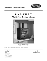
FEDS Inspection & Fitting
The Stratford EcoBoiler is not fitted with a traditional throat plate as found in most integrated boiler stoves,
instead a highly efficient Flue Exhaust Diverter System is incorporated. This allows far more heat to be
absorbed by the boiler jacket, and reduces the overall amount of heat wasted by slowing the flue gasses
passage up the chimney. This in turn helps to reduce the overall fuel quantities required to produce a
given amount of hot water and radiated heat to your room.
As with traditional throat plate designs the FEDS needs to be checked regularly to ensure any build up of
ash and other debris produced by the burning of solid fuel is removed. The inner section of the FEDS is
welded in place during manufacture and requires nothing more than the removal of any residues produced
by the flue gases that may have built up on the surfaces. The Outer FEDS should be removed from the
stove to allow access to the inner section, and cleaning of the outer section.
Due to the construction materials the outer FEDS section is both light and easy to remove. The outer
section is removed by the following method:-
With the stove door fully open, hold the bottom of the FEDS with both hands, palms on the bottom slop-
ing face. Push up firmly to release the FEDS from the retaining lugs (It may require a smart knock up-
wards with the palm of your hand to release it.) Once clean and cleared of debris replace by following the
reverse of the above procedure.
IMPORTANT:
This procedure should only be carried out with the stove unlit and cold.
The FEDS System
Inner FEDS
Outer FEDS
Retaining Lugs

12 Stratford EcoBoiler Stove
INSTALLATION
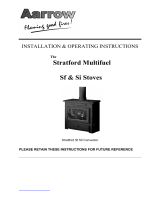
Fastening The Stove Canopy
Rear Flue Fitting
Before fitting the canopy ensure the stove top
insulation is seated correctly in the recess, see
fig. A, and if rear flue spigot connection is to be
used, fit the top hot plate.
Fig. A
Fasten the canopy onto the boiler body using the 2
off M6 wing nuts located on the top back face of
the boiler. The fixing method is the same for all 3
canopy styles, (Roll Top style shown), see fig. B
Fig. B
For rear flue operation fit the top flue blanking plate
as shown. The Slab top and Roll top canopy
blanking plates drop in place and requires no
fixings, see fig. C, The raised top canopy is held in
place by 2 off M6 wing nuts located on the under-
side of the blanking plate, see fig. D
Fig. C
Fig. D
Slab & Roll Top Blanking Plate
Raised Top Blanking Plate
Fastening the Canopy
Fitting the blanking plate
Please Note:
For the Slab top and Roll top canopy
the round blanking plate sits just slightly raised
from the canopy top face, the Raised top canopy
blanking plate sits flush into the recess formed in
the top surface.
Do not over tighten the wing nuts on the Raised
top blanking plate, they should be finger tight only
Warning:
The stove cannot be lifted by
the canopy once fitted.

Stratford EcoBoiler Stove 13
INSTALLATION
Fastening The Stove Canopy
Top Flue Fitting
When using the top flue spigot, the spigot should be fitted into the stove top outlet first.
The Slab top and Roll top design canopies should then be secured in place as shown in fig. B on page
12.
The connecting flue section between the stove and chimney can then be installed.
For Top flue exit using the Raised canopy fit the top flue spigot and connecting flue pipe first.
Then fit the Raised canopy as shown in fig. D on page 12.
The Top flue fillet kit can now be fitted as shown in fig. E. The crescent shape section is placed in front of
the flue pipe, and requires no fixings. The back section of the fillet kit is held in place by 2 x M5 wing nuts
on the under side of the fillet section.
Fig. E
Front section
Back section
Warning:
The stove CANNOT be lifted by the canopy once fitted.

14
INSTALLATION
FLUE OUTLET AND HOT PLATE
The flue spigot is found inside the appliance.
The hot plate is supplied fitted to the top open-
ing and is removed by turning clockwise (as is
the flue outlet)
Smear a very thin layer of fire cement on the
surfaces of the flue outlet and hot plate, fit the
outlet to the appliance in the desired position.
Lock into place by rotating anti-clockwise and
tighten by tapping with a block of wood and mal-
let from inside of the appliance. Similarly , fit the
hot plate to the unused opening. Clean off any
surplus fire cement.
Place appliance on the hearth and make sure
that it is level and does not rock.
Connect the chimney ensuring all joints are
sealed with fire cement.
FLUE AND SPIGOT FITTING
*Note
THE FLUE PIPE MUST BE FITTED INSIDE
THE OUTLET SPIGOT FAILURE TO DO SO
COULD RESULT IN THE SPILLAGE OF
CONDENSATION ETC. RUNNING DOWN THE
FLUE.
FLUES AND CHIMNEYS
The flue draw is critical on any installation and
should be checked to ensure that it matches what
is specified. If it is higher than recommended provi-
sion must be made to correct the overdraw.
The draw can vary in different weather conditions
and the customer should be made aware of this.
Failure to correct an over-drawing flue will invali-
date the warranty, and may damage the appliance.
Please remember that chimney draught is
dependent on four main factors.
• Flue gas temperature
• Flue height
• Flue size
• Flue terminal
The stove must be connected to a suitable and
efficient flue that provides a good up draught to
safely take the products of combustion (fumes)
from the stove outlet to the outside air.
To ensure a good up draught it is important that
the flue gases are kept warm and that the flue size
suits the stove.
The termination of the outlet at the top of the flue
also needs to comply with Building Regulations.
The minimum effective height of the flue must be
at least 4.5 meters from the top of the stove to the
top of the flue outlet. When warm the flue draught
should be between 0.1 and 0.2mb
(10-20 pa). A chimney may comply with the regu-
lations but still be subject to down draught and
similar problems. A chimney terminating above the
ridge level is generally less likely to suffer such
problems.
If a new chimney is being provided it should fully
comply with the relevant Building Regulations that
specify the requirements for solid fuel burning in-
stallations.
Suitable types of chimney include the following.
Masonry chimney built with clay or concrete lin-
ers, or a chimney block system.. These types of
chimney should comply with and be installed in
accordance with Building Regulations and
BS6461: part1.
Factory made insulated chimney complying with
BS 4543: part2 (often called ‘Class1 prefabricated
metal chimney’) and installed in accordance with
Building regulations and BS 7566: parts 1 to 4.
Stratford EcoBoiler Stove
Inside
Flue
Pipe
Outer
Spigot

Stratford EcoBoiler Stove
INSTALLATION
Due to the gradual introduction of European Chim-
ney Standards chimneys will be specified accord-
ing to their performance designation as defined in
BS EN 1443 that covers the General Requirements
for chimneys. The minimum performance designa-
tion required for use with solid fuel burning stove is
T450 N2 S D3
The flue and chimney installation must be carefully
checked by a competent person before fitting the
stove to ensure it is suitable and will work safely.
If the chimney is old (i.e. built of brick or stone with
out a liner) or being opened up for reuse additional
checks and smoke testing as described in Appendix
E of Approved Document J 2002 Edition should be
carried out to ensure the flue and chimney are in
good operating condition.
Unless the existing flue is in good condition with
suitable access for collection and removal of debris,
the flue size is more than 225mm (9”) diameter, or
200 x 200mm square, a suitable lining of 150mm
(6”) diameter should be fitted. If the flue length is
over 5.5metres one size larger than the appliance
outlet should be fitted, (6” min.). This should be a
double skin stainless steel flexible flue liner that is
independently certified for use with solid fuel. De-
tails of suitable linings for use with wood and solid
fuel are given in the official HETAS guide that can
be viewed on their website at www.hetas.co.uk -
(Heating Equipment Testing & Approval Scheme)
It is also important that a suitable flue pipe that com-
plies with the building Regulations is used to con-
nect the stove to the flue in the chimney and that
suitable access is provided into the flue for regular
inspection and sweeping of the flue ways.
The installer should comply with the Building Regu-
lation requirements in respect of providing a notice
plate giving details on the chimney, flue lining,
hearth and fireplace installation. Approved Docu-
ment J of the building regulations for England and
Wales is available from The Stationary Bookshops
and can also be viewed at the ODPM website at
www.safety.odpm.gov.uk/bregs/brads.htm
Details on the relevant Building Regulations and BS
British Standards are given in the ‘General Precau-
tions’ section of this manual.
Chimneys should be as straight as possible.
Horizontal runs should be avoided except where
the rear outlet of the appliance is used, in which
case the horizontal section should not exceed
150mm (6”) in length.
If the fire appears to be working hard but pro-
duces very little output to the room it is likely that
excessive draw is present in the chimney, and
that heat is being sucked out of the appliance and
up the chimney.
If this is the case we recommend the fitting of a
draught stabiliser in preference to a flue damper,
in the interests of safety and efficiency.
FOR ALL APPLIANCES
Access for cleaning the flue should be
incorporated in the system other than through
the appliance (e.g. a soot door or access though
the register plate). Purpose made soot doors and
inspection lengths are available from manufactur-
ers of all flue system.
Ensure that the whole length of the flue can be
reached from the soot door.
Note: if the appliance is fitted with a draught
stabiliser or if one is fitted to the flue pipe or
chimney in the same room as the appliance,
then the permanent air entry opening (or
openings) should be increased by 300mm² for
each kW of rated output.
For advice on flues and chimneys contact :-
NACE (National Association of Chimney
Engineers): Telephone 0800 0924019
Web address: www.nace.org.uk
Or
NACS (National Association of Chimney
Sweeps): Telephone 01785 811732
Web address: www.chimneyworks.co.uk
Or
HETAS (Official Body to Solid Fuel Domestic
Heating Appliances): Telephone 0845 634
5626
Web address: www.hetas.co.uk
15


Stratford EcoBoiler Stove
INSTALLATION
Typical Top Flue Outlet
(AS Per BS 8303-1)
Typical Metal Insulation Chimney System
To be installed to the chimney manufacturers instructions in compliance
with Building Regulations and BS7566 Pts 1 to 4
17
PLAN VIEW OF REGISTER PLATE AND
CLEARANCES FOR NON INSULATED FLUES
Steel register plate 1.5mm thick minimum

18 Stratford EcoBoiler Stove
INTEGRAL BOILERS
Integral boilers should be connected , with flow
and return connections of any circuit on opposite
sides of the appliance, (cross flowed), to indirect
hot water tank/system, adding Fernox or similar
corrosion inhibitor to prevent corrosion and for-
mation of lime scale.
It is also essential that the water temperature
remains in excess of 45° centigrade (Celsius).
The gravity circuit return should be fitted with a
pipe thermostat, which will activate a cut-out on
the radiator circulating pump, should the
temperature fall below this level. (45°C)
Connecting pipe work to the boiler unit.
The connected pipes should be screwed to a
maximum depth of 19mm from the face of the
tapping boss, (1.25” BSP, parallel).
Steel integral boilers should only be connected to
an indirect hot water tank system
Note:
the flow and return sections of any circuit
must always be opposite to the appliance.
Remember to incorporate a draining plug/tap
at the lowest point to facilitate draining and
flushing.
Warning: If a pipe-stat is not fitted to control
the radiator circulation pump then cold water
corrosion can occur
FAILURE TO COMPLY WITH THESE
REQUIREMENTS WILL INVALIDATE THE
GUARANTEE.
CHECKING THE THERMOSTAT AND PRESET-
TING TO THE CORRECT DAMPER PRES-
SURES
PLEASE NOTE:
The thermostat has been fitted and set correctly
during manufacturing. However it is advisable to
check the cold setting prior to lighting the fire for
the first time after installation.
With the control knob set fully clockwise (past
No.5) the circular damper plate should have a
gap of approximately 18mm between the damper
edge and the stove inner body face, measured at
the furthest point from the control knob and in line
with the actuation shaft. Take care to measure
this gap parallel to the actuation arm centre line.
If this is not the case follow the procedure as
detailed in the maintenance section on page 26.
CLEANING AROUND THE THERMOSTAT
For cleaning around the thermostat and removal
of ash build up see Maintenance section page
30.
It is important to regularly clean around the
damper to avoid an ash build up to maintain
proper control of the burn rate.
INSTALLATION

Stratford EcoBoiler Stove 19
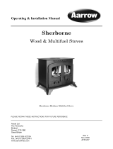
INSTALLATION
Central Heating and Domestic Hot water System Using Four Boiler Tapings
Central Heating Without Domestic Hot water System Using Four Boiler Tapings
Note: Diagrammatic representation only. Design and calculations for individual systems
should always be carried out by a qualified heating engineer

20 Stratford EcoBoiler Stove
INSTALLATION
Central Heating and Domestic Hot water System Using Three Boiler Tapings
Central Heating Without Domestic Hot water System Using Three Boiler Tapings
Note: Diagrammatic representation only. Design and calculations for individual systems
should always be carried out by a qualified heating engineer
/