Jandy AquaPure Workbook

Type
Workbook

This manual is also suitable for

Jandy AquaPure, PureLink
& Nature² Fusion Soft
Workbook
Zodiac Pool Systems, Inc.
1-800-822-7933
www.ZodiacPoolSystems.com
Instructor___________________________________________________ ext._________
Sales Representatives________________________________________ ext._________
__________________________________________________________ ext._________
Service Manager_____________________________________________ ext._________
__________________________________________________________ ext._________
2
Table of Contents
MODELS AND MODEL NUMBERS.................................................................................. 4
SIZING AND GENERATION PROCESS .......................................................................... 5
COMPONENTS .............................................................................................................6-7
NATURE² .......................................................................................................................... 8
INSTALLATION-
- PLUMBING ................................................................................................................9-11
- ELECTRICAL...........................................................................................................12-13
- CHEMISTRY............................................................................................................14-15
OPERATION ................................................................................................................... 16
TROUBLESHOOTING-
- TRANSFORMER VOLTAGE ...................................................................................17-18
- POWER INTERFACE BOARD (PIB) DC VOLTAGE .................................................... 19
- SENSOR INSPECTION................................................................................................ 20
- PIB SENSOR READINGS TEST .................................................................................. 21
- CELL INSPECTION ...................................................................................................... 22
- CELL VOLTAGE AND CURRENT ................................................................................ 23
- SERVICE CODE........................................................................................................... 24
- SERVICE CODE FLOW CHARTS...........................................................................25-28
ORIGINAL AQUAPURE, PURELINK, AND CM3 TEST POINTS-
- BACK BOARD TRANSFORMER AND CELL VOLTAGE TESTS................................. 29
- FRONT BOARD VOLTAGE TESTS ............................................................................. 30
- FRONT BOARD SENSOR READNGS TEST............................................................... 31
TABLE OF CONTENTS
3
CHLORINE GENERATION
Jandy PureLink, APureM,
& Nature² FusionM
(Require Cell Kit or Nature² Fusion Soft)
AquaPure
Chlorine Generation
Current Models:
COM 25
Discontinued Models:
ClorMatic II
ClorMatic III
Parts Still Available!
F
u
s
i
o
n
M
O
D
E
L
:
F
U
S
I
O
N
M
Finished Goods Part Numbers
“Chlorine Generators”
6613AP
PLC1400
Power Pack Model:
6614AP-L= Sub Panel Power Center PureLink for AL-RS/PDA
6613AP= Standard Power Center PureLink Generator for AL-RS/PDA
AquaPureM or Nature² FusionM = Stand Alone AquaPure/Nature² Fusion
Cell Model:
PLC= Cell Kit
FSOFT= Cell Kit with Nature2 Vessel
Size:
1400= 14 Plate Cell
700= 7 Plate Cell
4
CHLORINE GENERATION
H20
+
Sodium Chloride
(Salt - NaCl)
=
Sodium Hypochlorite
(Liquid Chlorine)
=
Sodium Chloride
(Salt - NaCl)
Bubbles Off
1
ANODE
Hypochlorous Acid
Hydrochloric Acid
2
CATHODE
Sodium Hydroxide
Hydrogen Gas
3
Hypochlorous Acid
+
Sodium Hydroxide
4
Hydrochloric Acid
+
Sodium Hydroxide
5
At a pH of 7.4, one half of
the Sodium Hypochlorite
goes into:
Hydrochloric Acid
+
Sodium Hydroxide
6
Hypochlorous Acid oxidizes soil,
dirt, algae, (organic material)
leaving:
7
Hydrochloric Acid
+
Sodium Hydroxide
8
Salt Recycled
Liquid Chlorine
Salt - NaCl
5
Notes:
_____________________________________________________________________
_____________________________________________________________________
_____________________________________________________________________
_____________________________________________________________________
Chlorine Production and Process
1.9 lbs.1.38 lbs1.25 gallons 1.25 lbs
0.95 lbs..69 lbs..625 gallons.625 lbs.
Calcium
Hypochlorite
90% Tri-Chlor
Tabs
Liquid Chlorine
(12.5%)
Gas Chlorine
700
1400
CHLORINE GENERATION
ORP
OPEN - AP700
SHORTED - AP1400
M-S
15
Green
Black & W hite
(+)
(-)
ORP
POS - 2
POS - 1
BUZZER
OFF ----
ON -----
ADDR ESS
A B De vice
0 0 # 1
1 0 # 2
0 1 # 3
1 1 # 4
A
B
DBI
INTERFACE
Mechanical
Sensor
ENB
DIS
FLOW SENSOR
H - Temp
R - Temp
Salinity
1 Amp FUSE
Salinity = 2.8
R Temp = 75
H Te mp = 91
TES T POINTS
ORP
OPEN - AP700
SHORTED - AP1400
M-S
15
Green
Black & W hite
(+)
(-)
ORP
POS – 2
POS - 1
BUZZER
OFF ----
ON -----
ADDRESS
A B Device
0 0 # 1
1 0 # 2
0 1 # 3
1 1 # 4
A
B
DBI
INTERFA CE
Mechanical
Sensor
ENB
DIS
FLOW SENSOR
H - Temp
R - T emp Salin ity
1 Amp FUSE
Salinity = 2.8
R Temp = 75
H Temp = 91
TEST POINTS
19 VAC
VAC 1
VAC 2
120 mVD C
65 VAC 75 VAC
15 Amp FUSE
+24 VDC
+5 VDC
COMMON
GROUN D
HEATER
RESTING
CELL ON
FLOW
SER VIC E
ORP
LOW SALT
+12 VDC
A
B
C
?
D
?
USER INTERFACE BOARD (UIB)
Replacement P/N: R0467400
POWER INTERFACE BOARD (PIB)
Replacement P/N: R0467600
PureLink
AquaPure/
Nature² Fusion Soft
Power Pack
AQUAPURE AND NATURE² FUSION POWER
PACKS
STAND ALONE POWER PACK
APUREM
NATURE² FUSIONM
PURELINK POWER CENTERS
STANDARD POWER CENTER
6613AP
SUB-PANEL POWER CENTER
6614AP-L
6
CHLORINE GENERATION
Low Voltage
Cord
Flow/Temp/Salinity
Sensor
Cell – 3 Port
7
Low Voltage
Cord
Flow/Temp/Salinity
Sensor
Nature² Fusion Soft
(Cell and Start Up Cartridge Included)
Nature²
Cartridge
NATURE² FUSION SOFT KITS
16’ CORDS
FSOFT700 (Up to 12,000 Gallons)
FSOFT1400 (Up to 40,000 Gallons)
NATURE² CARTRIDGES
W28000 = Single Cartridge for FSOFT700
W26000 = 4 Pack of Cartridges for FSOFT700
W28002 = Single Cartridge for FSOFT1400
W26002 = 4 Pack of Cartridges for FSOFT1400
CELL KITS
16’ CORDS
PLC700 (Up to 12,000 Gallons)
PLC1400 (Up to 40,000 Gallons)
25’ CORDS
PLC700-25
PLC1400-25
NATURE²
Notes:
_____________________________________________________________________
_____________________________________________________________________
_____________________________________________________________________
Nature² Benefits
The Bactericidal qualities of silver reduce the amount of chlorine required to maintain the
pool. The copper inhibits algae growth.
By Lowering the output of the chlorine generator, the pool water quality dramatically im-
proves and the life of the electrolytic cell is extended.
The Minerals
Copper– inhibits algae growth, regularly sold as algaecides
Silver– known bactericide, used for thousands of years to bacteria in water, milk, and on
skin
Porous Alumina– releases silver and copper, assists in trapping nuisance metals, algae,
and bacteria
The Facts
Copper is released into the pool at low levels (.02 - .06 ppm)
Silver is maintained throughout the cartridge life (6 months at .01 - .05 ppm)
Minimum pump run time is 6 hours, and can be run up to 24 hours
Nature²
Nature² Fusion Inground
• Nature² with Chlorine Tab Feeder
• Up to 45,000 Gallons
• 3 Cartridge Sizes
Professional G
• Stand Alone Nature²
• Up to 45,000 Gallons
• 3 Cartridge Sizes
Nature² Express
• Stand Alone Nature²
• After Market, Easy Install
• Up to 25,000 Gallons
Additional Nature² Products
8
CHLORINE GENERATION INSTALLATION – PLUMBING
3 Port Cell and Sensor
Preferred Plumbing
The “T” for the Flow/Temp/Salinity Sensor should
be pointed down to prevent air entrapment which
could cause false readings.
3 Port Cell and Sensor
OK Plumbing
The 3 Port Cell can be located so the sensor is
mounted to the side of the cell.
3 Port Cell and Sensor
OK Plumbing
The 3 Port Cell can be located so the sensor is
mounted to the top of the cell.
13 7/8” Cut Out
OK
9
CHLORINE GENERATION INSTALLATION - PLUMBING
Wrong
Wrong
3 Port Cell and Sensor
Wrong Plumbing
If the 3 Port Cell is plumbed as shown, the cell
may not produce chlorine, and the sensor will pro-
vide inaccurate readings.
3 Port Cell and Sensor
Wrong Plumbing
If the 3 Port Cell is plumbed as shown, the sensor
may provide inaccurate readings.
10
Notes:
_____________________________________________________________________
_____________________________________________________________________
_____________________________________________________________________
_____________________________________________________________________
CHLORINE GENERATION INSTALLATION - PLUMBING
13 7/8” Cut Out
11 1/8”
Center
of Pipe
Nature² Fusion
Proper Plumbing
The Flow/Temp/Salinity must be plumbed on the
inlet side of the Nature² Fusion.
11
Notes:
_____________________________________________________________________
_____________________________________________________________________
_____________________________________________________________________
_____________________________________________________________________
CHLORINE GENERATION INSTALLATION - ELECTRICAL
To Covert a Power Interface Board (PIB)
from a 1400 to a 700 cut the jumper
1400 700
Cell Low
Voltage
Cable
Extension
wires from
the PIB
Cell Low
Voltage
Cable
Black/White
Wire
Green
Wire
Black Wire &
White Wire
Green
Wire
Cell Low Voltage
Cable Extension
Cell Low
Voltage Cable
Original New
Black/White
Wire
Green
Wire
Black Wire &
Blue Wire
Red
Wire
Cell Low Voltage
Cable Extension
Cell Low
Voltage Cable
12
Cell Low Voltage Cable Connection
CHLORINE GENERATION INSTALLATION - ELECTRICAL
Versa Plumb- 3 Port Cell
Cell should be the last item
on the equipment pad
Connected to load side
of time clock or relay.
All electrical equipment
connected by bond wire.
Versa Plumb- Nature² Fusion Soft
Cell should be the last item
on the equipment pad
Connected to load side
of time clock or relay.
All electrical equipment
connected by bond wire.
13
CHLORINE GENERATION INSTALLATION - CHEMISTRY
START-UP
Before starting a chlorine generator
• Balance the pool water
• Super chlorinate if needed.
• Add a metal remover.
WATER CHEMISTRY
Free chlorine - 1.0 to 3.0 (Low of .5 is possible with the Nature² Fusion)
• pH - 7.2 to 7.8
• Total Alkalinity - 80 to 120 ppm
• Cyanuric Acid (Stabilizer) - 10 to 100 ppm
• Total Dissolved Solids (TDS) - Less than 2000 ppm.
(Subtract salinity level to arrive at corrected level.)
14
13
12
11
10
9
8
7
6
5
4
3
2
1
Acidic
Alkaline
10 x
10 x 10 = 100 x
10 x 10 x 10 = 1,000 x
10 x 10 x 10 x 10 = 10,000 x
Neutral
pH SCALE
14
Notes:
_____________________________________________________________________
_____________________________________________________________________
_____________________________________________________________________
CHLORINE GENERATION INSTALLATION - CHEMISTRY
SALT
As a general guideline, the purer the salt the better the performance and the longer the “life” of the cell.
Calcium and magnesium are the enemies of the cell and cause scaling, poor performance and short-
ened anode life.
It is recommended to use food grade salt only with the following characteristics:
Minimum 99.8% pure NaCl
No added anti-caking agents
No sodium ferrocyanides (aka - yellow prussiate of soda)
Non-iodized.
CALIBRATED X
NaCl
Testing Salt Level
Myron L Meter
Calibrated to test for NaCl
SALT TEST METER
MYRON L METER
P/N - M1003
SALT ADJUSTMENT CHART
Add 1.25 lbs. of stabilizer for every
50 lbs. of salt.
Pool Size
Current
Salinity
10,000 14,000
18,000 20,000 24,000 28,000 30,000
0.0 gpl 250 lbs 350 lbs 450 lbs 500 lbs 600 lbs 700 lbs 750 lbs
1.0 gpl 165 lbs 230 lbs 300 lbs 330 lbs 400 lbs 460 lbs 495 lbs
1.5 gpl 125 lbs 175 lbs 225 lbs 250 lbs 300 lbs 350 lbs 375 lbs
2.0 gpl 85 lbs 120 lbs 150 lbs 170 lbs 205 lbs 240 lbs 255 lbs
2.5 gpl 40 lbs 60 lbs 70 lbs 80 lbs 100 lbs 110 lbs 120 lbs
3.0 gpl 0 lbs 0 lbs 0 lbs 0 lbs 0 lbs 0 lbs 0 lbs
Salt Adjustment Chart to Achieve 3.0 gpl
(food grade salt only)
0.0 gpl
0.3 gpl
0.5 gpl
0.8 gpl
1.0 gpl
1.3 gpl
1.5 gpl
1.8 gpl
2.0 gpl
2.3 gpl
2.5 gpl
2.8 gpl
25.6 lbs. (11.6 kg)
23.5 lbs. (10.7 kg)
21.4 lbs. (9.7 kg)
19.2 lbs. (8.7 kg)
17.1 lbs. (7.8 kg)
15.0 lbs. (6.8 kg)
12.8 lbs. (5.8 kg)
10.7 lbs. (4.8 kg)
8.5 lbs. (3.9 kg)
6.4 lbs. (2.9 kg)
4.2 lbs. (1.9 kg)
2.2 lbs. (1 kg)
Salt Concentration,
Before Addition
Salt Addition Required
per 1000 gallon pool capacity
Approximate Pound (kg) of Salt Needed to Maintain 3.0 gpl (3000 PPM)
SALT MAINTENANCE CHART
15
CHLORINE GENERATION - OPERATION
FACTORS WHICH AFFECT CHLORINE RESIDUAL
Model/Size of chlorine generator.
How long the chlorine generator is ON.
Setting of Production Percentage of the chlorine generator.
Salt level.
Water chemistry.
Water temperature.
Covered or uncovered.
Water features.
Bathing load.
Other organic matter (e.g. Phosphates).
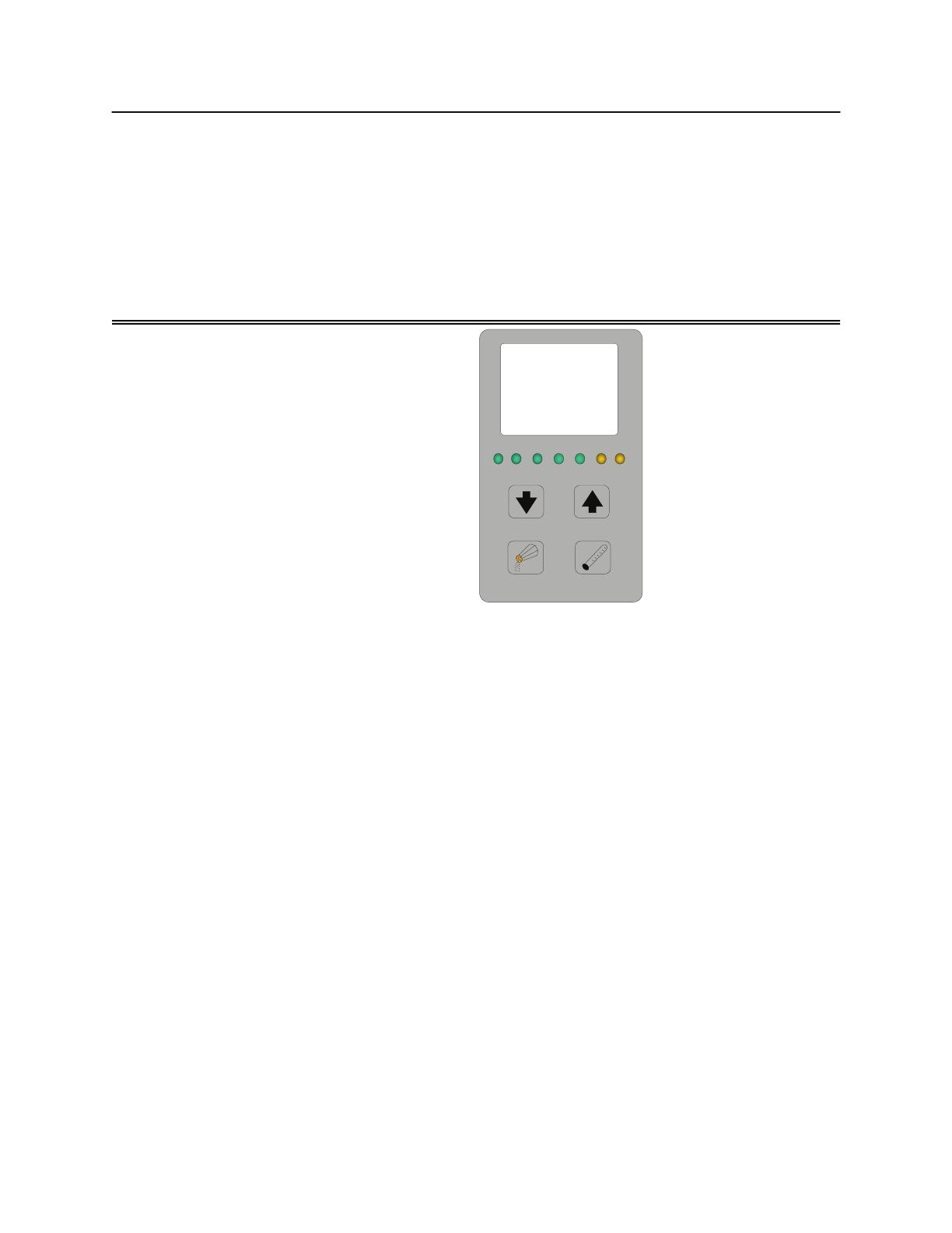
AQUAPURE LCD DISPLAY
CELL ON
CELL
RESTING
FLOW
CELL
REVERSING
ADD SALT
SERVICE
CHLORINE
PRODUCTION RATE
Salinity
Pool
Temp
-Boost-
POWER
ON
AB
C
?
D
?
Flow
No
Wait
Chlorine
Production
%
GPL
100
16
WHAT THE LCD DISPLAY MEANS
50 or 60 - The unit is detecting the electrical supply to optimize the unit settings. 60 cycles power is the
US standard. If the unit detects 60 cycles, it will display the temperature in degrees F. 50 cycles is com-
mon in Europe.
CHLORINE PRODUCTION - displays the current production percentage rate for chlorine.
WAIT - the unit is still testing its diagnostics.
NO FLOW - the unit is still testing its diagnostics, or no water flow is detected.
FLOW - the flow sensor is indicating to the unit it has enough water flow.
LO - indicates the water temperature is less than 51 degrees F.
BO - boost cycle has been activated. Cancel by holding the POOL TEMPERATURE button down for 10
seconds.
EC - the unit is being controlled by an external controller or ORP device.
JA - indicates operation is controlled by a Jandy AquaLink RS or PDA, and is in AUTO mode.
JO - indicates operation is controlled by a Jandy AquaLink RS or PDA, and the system is in SERVICE or
TIMEOUT mode.
JB - indicates operation is controlled by a Jandy AquaLink RS or PDA, and the system is in BOOST
mode.
WHAT THE INDICATOR LIGHTS MEAN
CELL ON - Full power is being sent to the cell.
CELL RESTING - The cell is in the off portion of chlorine production cycle. Cycle time is 30 minutes. As an
example, when the chlorine production rate is set to 50%, full power will be applied to the cell for 15 min-
utes and then no power (CELL RESTING) for the next 15 minutes.
FLOW - The sensor is detecting water flow.
CELL REVERSING - Control switches polarity to the cell every 3 hours to help clean the plates. The cell
will rest for 3 minutes between switching of polarity.
ADD SALT - Salinity level is 2.5 gpl or less. Should be 3.0 to 3.5 gpl.
SERVICE - A service problem has been detected. The display will also show one or two error codes.
POWER ON - Power is being sent to the control and received at the User Interface Board
TROUBLESHOOTING - TRANSFORMER VOLTAGE
This test confirms the proper secondary
voltage is coming out of the transformer.
ORP
OPEN - AP700
SHORTED - AP1400
M-S
15
Green
Black & White
(+)
(-)
ORP
POS - 2
POS - 1
BUZZER
OFF ----
ON -----
ADDRE SS
A B De vice
0 0 # 1
1 0 # 2
0 1 # 3
1 1 # 4
A
B
DBI
INTERFACE
Mechanical
Sensor
ENB
DIS
FLOW SENSOR
H - Temp
R - Temp
Salinity
1 Amp FUSE
Salinity = 2.8
R Temp = 75
H Te mp = 91
TES T POINTS
ORP
OPEN - AP700
SHORTED - AP1400
M-S
15
Green
Black & White
(+)
(-)
ORP
POS – 2
POS - 1
BUZZER
OFF ----
ON -----
ADDRESS
A B Device
0 0 # 1
1 0 # 2
0 1 # 3
1 1 # 4
A
B
DBI
INTERFACE
Mechanical
Sensor
ENB
DIS
FLOW SENSOR
H - Temp
R - T emp Salinit y
1 Amp FUSE
Salinity = 2.8
R Temp = 75
H Te mp = 91
TEST POINTS
19 VAC
VAC 1
VAC 2
120 mVDC
65 VAC 75 VAC
15 Amp FUSE
+24 VDC
+5 VDC
COMMON
GROUN D
HEAT ER
RESTING
CELL ON
FLOW
SERV IC E
ORP
LOW SA LT
+12 VDC
First Test:
Set the meter to 200 ACV or
higher. Put the leads on the 75
VAC test points. The voltage
should be between 67 to 87.
If the voltage is outside this
range, replace the Trans-
former.
1 Amp FUSE
19 VAC
VAC 1
VAC 2
65 VAC 75 VAC
+24 VDC
+5 VDC
COMMON
+12 VDC
DCV
W
2000K
200K
20K
2K
h
FE
2
20
200
1000
200
750
PNPNPN
OFF
200m
DCA
20m
200m
10A
200
ACV
200µ
2000µ
75
Second Test:
Set the meter to 200 ACV or
higher. Put the leads on the 65
VAC test points. The voltage
should be between 60 to 75
If the voltage is outside this
range, replace the Trans-
former.
1 Amp FUSE
19 VAC
VAC 1
VAC 2
65 VAC 75 VAC
+24 VDC
+5 VDC
COMMON
+12 VDC
DCV
W
2000K
200K
20K
2K
h
FE
2
20
200
1000
200
750
PNPNPN
OFF
200m
DCA
20m
200m
10A
200
ACV
200µ
2000µ
65
17
TROUBLESHOOTING - TRANSFORMER VOLTAGE
1 Amp FUSE
19 VAC
VAC 1
VAC 2
65 VAC 75 VAC
+24 VDC
+5 VDC
COMMON
+12 VDC
DCV
W
2000K
200K
20K
2K
hFE
2
20
200
1000
200
750
PNPNPN
OFF
200m
DCA
20m
200m
10A
200
ACV
200µ
2000µ
19
Third Test:
Set the meter to 200 ACV or higher. Put the leads on VAC 1 & VAC 2 of the 19 VAC
test points. The voltage should be between 17 to 24.
If no voltage is present, check 1 Amp Fuse on PIB.
If the voltage is outside the above range, replace the Transformer.
18
Notes:
_____________________________________________________________________
_____________________________________________________________________
_____________________________________________________________________
_____________________________________________________________________
TROUBLESHOOTING - PIB DC VOLTAGE
ORP
OPEN - AP700
SHORTED - AP1400
M-S
15
Green
Black & White
(+)
(-)
ORP
POS - 2
POS - 1
BUZZER
OFF ----
ON -----
ADDRESS
A B De v ice
0 0 # 1
1 0 # 2
0 1 # 3
1 1 # 4
A
B
DBI
INTERFACE
Mechanical
Sensor
ENB
DIS
FLOW SENSOR
H - Temp
R - Temp
Salinity
1 Amp FUSE
Salinity = 2.8
R Temp = 75
H Te mp = 91
TES T POIN TS
ORP
OPEN - AP700
SHORTED - AP1400
M-S
15
Green
Black & White
(+)
(-)
ORP
POS – 2
POS - 1
BUZZER
OFF ----
ON -----
ADDRESS
A B Device
0 0 # 1
1 0 # 2
0 1 # 3
1 1 # 4
A
B
DBI
INTERFACE
Mechanical
Sensor
ENB
DIS
FLOW SENSOR
H - Temp
R - T emp Salinity
1 Amp FUSE
Salinity = 2.8
R Temp = 75
H Te mp = 91
TEST POINTS
19 VAC
VAC 1
VAC 2
120 mVDC
65 VAC 75 VAC
15 Amp FUSE
+24 VDC
+5 VDC
COMMON
GROUN D
HEAT ER
RESTING
CELL ON
FLOW
SERV IC E
ORP
LOW SA LT
+12 VDC
This test confirms that the Power Inter-
face Board (PIB) is taking the AC Volt-
age from the Transformer and converting
it to DC Voltage.
19 VAC
VAC 1
VAC 2
+24 VDC
+5 VDC
COMMON
+12 VDC
DCV
W
2000K
200K
20K
2K
hFE
2
20
200
1000
200
750
PNPNPN
OFF
200m
DCA
20m
200m
10A
200
ACV
200µ
2000µ
12
First Test:
Set the meter to 200 DCV or
higher. Put the leads on the
Common & +12 VDC test
points. The voltage should be
between 11.8 to 12.2.
If the voltage is outside the
above range, replace the PIB.
19 VAC
VAC 1
VAC 2
+24 VDC
+5 VDC
COMMON
+12 VDC
DCV
W
2000K
200K
20K
2K
h
FE
2
20
200
1000
200
750
PNPNPN
OFF
200m
DCA
20m
200m
10A
200
ACV
200µ
2000µ
5
Second Test:
Set the meter to 200 DCV or
higher. Put the leads on the
Common & +5 VDC test points.
The voltage should be between
4.8 to 5.2.
If the voltage is outside the
above range, replace the PIB.
19
FLOW/TEMP/SALINITY SENSOR
The Sensor determines flow by comparing the temperature differ-
ential between the heated and unheated test pads. Salinity is
measured by the two “silver” test pads. These pads should be
kept clean to insure accuracy.
FLOW/TEMP/SALINITY SENSOR REVISION
Current Revisions are HX19 and JX 11
FLOW/TEMP/SALINITY SENSOR CLEANING
Once per year, or as needed, clean the sensor as follows:
1. Remove Flow/Temp/Salinity Sensor.
2. Brush with a mildly abrasive green fiber household
cleaning pad. Contacts should be clean and bright
when done.
3. Thoroughly rinse the Flow/Temp/Salinity Sensor with
clean tap water. Replace and resume normal operation.
4. Turn power off and back on to re-calibrate and reset
Flow/Temp/Salinity Sensor.
PROBLEMS:
Failure to shut of power.
Failure to indicate flow.
Incorrect salt indications.
CAUSES:
Broken or damaged wires.
Calcified sensor(s).
Failed electrical component.
System not Bonded.
20
Notes:
_____________________________________________________________________
_____________________________________________________________________
_____________________________________________________________________
Salinity Sensor Studs
Heated Temperature Probe
Hidden unheated
Temperature Probe
TROUBLESHOOTING - SENSOR INSPECTION
Look for JX 11
printed on label
  • Page 1 1
  • Page 2 2
  • Page 3 3
  • Page 4 4
  • Page 5 5
  • Page 6 6
  • Page 7 7
  • Page 8 8
  • Page 9 9
  • Page 10 10
  • Page 11 11
  • Page 12 12
  • Page 13 13
  • Page 14 14
  • Page 15 15
  • Page 16 16
  • Page 17 17
  • Page 18 18
  • Page 19 19
  • Page 20 20
  • Page 21 21
  • Page 22 22
  • Page 23 23
  • Page 24 24
  • Page 25 25
  • Page 26 26
  • Page 27 27
  • Page 28 28
  • Page 29 29
  • Page 30 30
  • Page 31 31
  • Page 32 32

Jandy AquaPure Workbook

Type
Workbook
This manual is also suitable for

Ask a question and I''ll find the answer in the document

Finding information in a document is now easier with AI