Page is loading ...

Installation Data
Installation Manual
All Button and
OneTouch
TM
Control
Systems
WARNING
FOR YOUR SAFETY - This product must be installed and serviced by a professional pool/
spa service technician. The procedures in this manual must be followed exactly. Failure to
follow warning notices and instructions may result in property damage, serious injury, or
death.
Pool/Spa Combination Systems and
Pool/Spa Only Systems
Sheet #6594, Rev. K


Page 3
Table of Contents
Section 1. Important Safety Instructions ...........4
Section 2. System Overview .............................
6
2.1 Package Contents ...........................
6
2.2 SystemComponentSpecications
and Dimensions ...............................7
2.3 Basic Plumbing ...............................
8
Section 3. Installation ........................................
10
3.1 Power Center Mounting ..................
10
3.2 High Voltage Wiring .......................
10
3.3 Low Voltage Wiring ........................
14
3.4 Heater Connection ..........................
15
3.5 Temperature Sensors .......................
18
3.6 Jandy Valve Actuators .....................
18
3.7 Auxiliary Power Centers .................
18
3.8
All Button Control Panel Installation
..
19
3.9
OneTouch Control Panel Installation
..
20
3.10 Wireless OneTouch Control Panel
Installation ......................................22
Section 4. System Startup .................................
24
4.1 All Button Programming ...............
24
4.2 All Button Reset and Display
Messages ........................................26
4.3 OneTouch Programming ................
26
4.4 OneTouch Reset and Display
Messages .........................................27
4.5 All Button and OneTouch System
Defaults and General Modes ..........28
4.6 All Button Menu Flow Chart ..........
30
4.7 OneTouch Menu Flow Chart ..........
31
Section 5. Troubleshooting ................................
32
5.1 All Button and OneTouch Quick
Troubleshooting Guide ...................32
5.2 Wireless OneTouch Quick
Troubleshooting Guide ...................33
Section 6. Power Center Wiring Diagram .........
35
Section 7. Power Center PCB DIP Switch
Settings .............................................36
7.1 DIP Switch Functions .....................
36
7.2 DIP Switch Settings for Pool and Spa
Combination ...................................37
7.3 DIP Switch Settings for Pool or
Spa Only .........................................38
Section 8. General, Water Feature and Light
Aux Labels .......................................39
Warranty ..........................................................
40
DATE OF INSTALLATION
INSTALLER INFORMATION
INITIAL PRESSURE GAUGE READING (WITH CLEAN FILTER)
PUMP MODEL
HORSEPOWER
FILTER MODEL
SERIAL NUMBER
CONTROL PANEL MODEL SERIAL NUMBER
NOTES:
EQUIPMENT INFORMATION RECORD

Page 4
Section 1. Important Safety Instructions
READ AND FOLLOW ALL INSTRUCTIONS
Lire la notice technique.
All electrical work must be performed by a licensed electrician and conform to all national, state, and
local codes. When installing and using this electrical equipment, basic safety precautions should always be
followed, including the following:
WARNING
Prolonged immersion in hot water may induce hyperthermia. Hyperthermia occurs when the internal temperature
of the body reaches a level several degrees above the normal body temperature of 98.6° F. The symptoms of
hyperthermia include dizziness, fainting, drowsiness, lethargy, and an increase in the internal temperature of the
body. The effects of hyperthermia include: 1) unawareness of impending danger; 2) failure to perceive heat; 3)
failure to recognize the need to exit spa; 4) physical inability to exit spa; 5) fetal damage in pregnant women; 6)
unconsciousness resulting in a danger of drowning.
DANGER
To reduce the risk of injury, do not remove the suction fittings of your spa or hot tub. Never operate a spa or hot
tub if the suction fittings are broken or missing. Never replace a suction fitting with one rated less than the flow rate
marked on the equipment assembly.
WARNING
To Reduce the Risk of Injury -
a) The water in a spa should never exceed 104°F (40°C). Water temperatures between 100°F (38°C) and
104°F (40°C) are considered safe for a healthy adult. Lower water temperatures are recommended for young
children and when spa use exceeds 10 minutes.
b) Since excessive water temperatures have a high potential for causing fetal damage during the early months of
pregnancy, pregnant or possibly pregnant women should limit spa water temperatures to 100°F (38°C).
c) Before entering a spa or hot tub, the user should measure the water temperature with an accurate
thermometer since the tolerance of water temperature-regulating devices varies.
d) The use of alcohol, drugs, or medication before or during spa or hot tub use may lead to unconsciousness with
the possibility of drowning.
e) Obese persons and persons with a history of heart disease, low or high blood pressure, circulatory system
problems, or diabetes should consult a physician before using a spa.
f) Persons using medication should consult a physician before using a spa or hot tub since some medication
may induce drowsines while other medication may affect heart rate, blood pressure, and circulation.
WARNING
Risk of electric shock - Install the power center at least five (5) feet (152.4cm) from the inside wall of the pool
and/or hot tub using non-metallic plumbing. Canadian installations must be at least three (3) meters (10 feet) from
the water.
Children should not use spas or hot tubs without adult supervision.
Do not use spas or hot tubs unless all suction guards are installed to prevent body and hair entrapment.
People using medications and/or having an adverse medical history should consult a physician before using a spa
or hot tub.
AVERTISSEMENT
Danger d'electrocution - Les installations Canadiennes doivent se trouver à au moins trois (3) mètres de l’eau.
Ne pas laisser les enfants utiliser une cuve de relaxation sans surveillance.
Pour éviter que les cheveux ou une partie du corps puissent être aspirés, ne pas utiliser une cuve de relaxation si
les grilles de prise d'aspiration ne sont pas toutes en place.
Les personnes qui prennent des médicaments ou ont des problèmes de santé devraient consulter un médecin
avant d’utiliser une cuve de relaxation.

Page 5
CAUTION
A ground-fault circuit-interrupter must be provided if this device is used to control underwater lighting fixtures. The
conductors on the load side of the ground-fault circuit-interrupter shall not occupy conduit, boxes, or enclosures
containing other conductors unless the additional conductors are also protected by a ground-fault circuit-
interrupter. Refer to local codes for complete details.
CAUTION
A terminal bar marked "GROUND" is provided within the power center. To reduce the risk of electrical shock,
connect this terminal bar to the grounding terminal of your electric service or supply panel with a continuous
copper conductor having green insulation and one that is equivalent in size to the circuit conductors supplying this
equipment, but no smaller than no. 12 AWG (3.3mm). In addition, a second wire connector should be bonded with
a no. 8 AWG (4.115mm) copper wire to any metal ladders, water pipes, or other metal within five (5) feet (1.52m)
of the tub.
SAVE THESE INSTRUCTIONS
WARNING
People with infectious diseases should not use a spa or hot tub.
To avoid injury, exercise care when entering or exiting the spa or hot tub.
Do not use drugs or alcohol before or during the use of a spa or hot tub to avoid unconsciousness and possible
drowning.
Pregnant or possibly pregnant women should consult a physician before using a spa or hot tub.
Water temperature in excess of 100°F/38°C may be injurious to your health.
Before entering a spa or hot tub measure the water temperature with an accurate thermometer.
Do not use a spa or hot tub immediately following strenuous exercise.
Prolonged immersion in a spa or hot tub may be injurious to your health.
Do not permit any electric appliance (such as a light, telephone, radio, or television) within 5 feet (1.5 m) of a spa
or hot tub.
The use of alcohol, drugs or medication can greatly increase the risk of fatal hyperthermia in hot tubs and spas.
Water temperature in excess of 100°F/38°C may be hazardous to your health.
AVERTISSEMENT
Les personnes atteintes de maladies infectieuses ne devraient pas utiliser une cuve de relaxation.
Pour éviter des blessures, user de prudence en entrant dans une cuve de relaxation et en sortant.
Pour éviter l’évanouissement et la noyade éventuelle, ne prendre ni drougue ni alcool avant d’utiliser une cuve de
relaxation ni quand on s’y trouve.
Les femmes enceintes, que leur grossesse soit conrmée ou non, devraient consulter un médecin avant d’utiliser
une cuve de relaxation.
Il peut être dangereux pour la santé de se plonger dans de l’eau à plus de 38°C/100°F.
Avant d’utiliser une cuve de relaxation mesurer la témperature de l’eau à l’aide d’un thermomètre précis.
Ne pas utiliser une cuve de relaxation immédiatement après un exercice fatigant.
L’utilisation prolongée d’une cuve de relaxation peut être dangereuse pur la santé.
Ne pas placer d'appareil électrique (luminaire, téléphone, radio, téléviseur, etc) à moins de 1.5m de cette cuve de
relaxation.
La consommation d’alcool ou de drogue augmente considérablement les risques d’hyperthermie mortelle dans
une cuve de relaxation.
Il peut etrê dangereux pour la santé de se plonger dans de l’eau à plus de 38°C/100°F.
Attention installer: Install to provide drainage of compartment for electrical components.
WARNING
To avoid injury ensure that you use this control system to control only packaged pool/spa heaters which have built-
in operating and high limit controls to limit water temperature for pool/spa applications. This device should not be
relied upon as a safety limit control.

Page 6
Section 2. System Overview
2.1 Package Contents
Package contents will depend on which AquaLink RS System you are installing. All Jandy AquaLink RS
Systems come complete with the appropriate number of 3HP relays needed.
Control System Sub-Assemblies
All Button OneTouch Wireless OneTouch
Power Centers
OneTouch Control Panel,
Power Center PCB,
Two (2) Temp Sensors,
Additional Relays,
Two (2) JVAs (Pool/Spa Combo
Systems)
All Button Control Panel,
Power Center PCB,
Two (2) Temp Sensors,
Additional Relays,
Two (2) JVAs (Pool/Spa Combo
Systems)
Wireless OneTouch Control Panel,
Outdoor Transceiver J-box,
Power Center PCB,
Two (2) Temp Sensors,
Additional Relays,
Two (2) JVAs
Standard Power Center
(with mounting brackets)
Sub-Panel Power Center
(with mounting brackets)
PureLink Power Center
(with mounting brackets)

Page 7
2.2 SystemComponentSpecicationsandDimensions
Table 1
Specifications (USA and Canada)
Power Supply 120 VAC; 60 Hz; 3 A
Contact Rating High voltage - 25 A; 3HP @ 240 VAC
1½ HP @120 VAC
1500 Watts Incandescent
Low Voltage - Class Two, 1 A @ 24 VAC
Service Switch All Circuits (located at Power Center in Service Mode)
Specifications (European)
Power Supply 230-240VAC; 50/60 Hz; 3 A
Contact Rating High voltage - 25 A; 3HP @ 240 VAC
Low Voltage - Class Two, 1 A @ 24 VAC
Service Switch All Circuits (located at Power Center in Service Mode)
Dimensions
8"
5"
1¼"
5½"
1½"
5"
4½"
4½"
1¼"
All Button
Control Panel
OneTouch
Control Panel
Wireless Control
Panel
Standard
Power Center
5"
14½"
13¾"
Sub-Panel
Power Center
20"
14½"
5"

Page 8
2.3 Basic Plumbing
2.3.1 PlumbingforPoolandSpaCombination
The following plumbing diagrams illustrate
simplified versions of standard plumbing setups
for a pool and spa that share the same filter pump,
filter, and heater. The intake and return JVA’s
turn simultaneously so when the Spa button
is pressed on the AquaLink RS Control Panel,
water circulation switches between pool and spa
(consult the Jandy Valve Actuator Installation and
Operation Manual to ensure that the JVA’s are
synchronized and rotate properly). Please consult
the Jandy Valve Plumbing Manual for further
examples of pool/spa plumbing.
Heater
Filter
Filter
Pump
Pool Drain
Spa Drain
Spa ReturnPool Return
Check
Valve
Spa
Make-up
Check
Valve
Heat Pump
SkimmersSkimmers
From Solar
To Solar
For Pool Only/Spa Only or Dual Equipment
plumbing, please refer to the Jandy Valve Plumbing
Manual for further examples.
NOTE When the filter system is shared (a Pool/Spa
Combo), the spa water must be able to overflow
back to the pool.

Page 9
2.3.2 Booster Pump Pool Cleaner Plumbing
Heater
Filter
Filter
Pump
Pool Intake Spa Intake
Spa ReturnPool Return
Check
Valve
Spa Make-up
Booster
Pump
2.3.3 Non-Booster Pump Pool Cleaner Plumbing
Heater
Filter
Filter
Pump
Pool Intake Spa Intake
Spa Return
Pool Return
Check
Valve
Spa Make-up
Energy
Filter
Cleaner
Line

Page 10
3.1 Power Center Mounting
1. The Power Center should be located at or
near the equipment pad. Locate the Power
Center at least five (5) feet or more away
from pool/spa and five (5) feet off the
ground. All national, state, and local codes
are applicable.
NOTE For Canadian installations, the Power Center
must be at least three (3) meters (9.8 feet)
away from the pool/spa and 1.5 meters (5 feet)
above the ground.
2. Use the mounting brackets and instructions
provided with the Standard Power Center
and/or Sub-Panel Power Center.
3. Sub-Panel Power Centers have special
code requirements. Be sure to follow all
applicable local and state codes to insure
safe installation.
NOTE The Power Center is not to be considered
as suitable for use as Service Equipment.
Therefore, it is required to have the appropriate
means of disconnection, circuit isolation, and/or
branch circuit protection installed upstream of
the Power Center.
3.2 High Voltage Wiring
3.2.1 System Power
Figure 2. Sub-Panel Power Center
Transformer
Earth Ground
Black
White
Primary
Low voltage raceway, do not run high voltage in this compartment
From Main
Power
Ground
White
White
Black
Black
Transformer
Earth Ground
Breaker Panel
To 120 VAC
Breaker
Neutral
Black
White
Wire nut to
120 VAC power
Low voltage raceway, do not run high voltage in this compartment
Primary
Figure 1. Standard Power Center
Section 3. Installation
WARNING
Potentially high voltages in the AquaLink RS
Power Center can create dangerous electrical
hazards, possibly causing death, serious injury
or property damage. Turn off power at the main
circuit of the AquaLink RS Power Center to
disconnect the Power Center from the system.
To properly and safely wire the system, be sure
to carefully follow the applicable requirements
of the National Electrical Code (NEC), NFPA 70
or the Canadian Electrical Code (CEC), CSA
C22.1. All applicable local installation codes
must also be adhered to.
Depending on the amount of equipment being
controlled, run ½" or ¾" conduit from the power
supply panel to the bottom of the Power Center.
If you are using the Sub-Panel Power Center,
wire power to the appropriate breakers. Pull in
appropriate wire for equipment. Each piece of
equipment requires its own high voltage relay.
Connect 120 volts to the Power Center terminals.
Connect equipment ground(s). See Figures 1 and 2.

Page 11
3.2.3 BondingthePowerCenter
Install a bonding lug to the Power Center
enclosure. Connect the bond lug, using a #8 solid
copper core wire, to an approved earth ground (an
approved ground stake, grid, or conducting metal
water pipe buried to a sufficient depth). See Figure
3.
3.2.2 3HP(Standard)Relays
For each piece of 240 volt equipment to be
controlled, connect line power to the two (2) line
terminals and connect equipment power to the two
(2) load terminals on the same relay.
For each piece of 120 volt equipment, connect
power to a line terminal and connect equipment to
a load terminal on the same relay.
NOTE The following are the contact ratings for 3HP
(Standard) Relay. DO NOT exceed any ratings.
3 HP @ 240 VAC; 1½ HP @ 120 VAC; 25
Amps; 1500 Watts.
Figure 3. Standard Power Center - Bonding
Bonding Lug
Earth
Ground
Breaker
Panel
Blower (120
VAC)
Filter
Pump (240
VAC)
Primary
24 VAC
Transformer

Page 12
3.2.4 UnderwaterLightingGFCIWiring
Figure 4. GFCI Installation for Underwater
Lighting
GFCI
Outlet
OPTIONAL
Standard Power Center
GFCI Outlet
(Optional)
OPTIONAL
Sub-Panel Power Center
3.2.5 JandyPoolandSpaLightsWiring
The JandyPoolandSpaLights can be wired into
the Jandy AquaLink RS control system to ensure
simplified operation of the lights, as well as a
means to synchronize the color change function.
Connect the lights to one of the auxiliary relays in
the Power Center.
NOTE It is recommended to connect one light per
relay so each light can be controlled separately.
However, up to four lights can be connected on
a single relay. If there are more than four lights
installed on one AquaLink RS system, ensure
there is more than one auxiliary relay available
in the Power Center.
Refer to Figures 5 and 6 to connect the Jandy Pool
and Spa Lights to the Power Center.
NOTE The Jandy Pool and Spa Lights are available
in 120-volt and 12-volt versions. If installing a
12-volt light, a 120-volt/12-volt step-down (AC)
transformer must be used. For more information
about 12-volt installations, refer to the Jandy
Digital,Color Changing,Underwater Pool and
Spa Lights Installation and Operation Manual.
CAUTION
A Ground Fault Circuit Interrupter (GFCI) must be
provided in high voltage pool/spa lights. Do not
use a GFCI circuit breaker.The conductors on
the load side of the GFCI circuit shall not occupy
conduit, boxes, or enclosures containing other
conductors unless the other conductors are also
on the load side of a GFCI. Refer to local codes
for complete details.
1. For a Standard Power Center, install a GFCI
receptacle next to the breaker panel. For
a Sub-Panel Power Center install a GFCI
receptacle in the Power Center (use the
knockout provided on the right side of the
Sub-Panel Power Center). See Figure 4.
2. Connect neutral and hot wire (from circuit
breaker) to the LINE side of the GFCI.
3. Connect neutral (white wire) and the hot
(black wire) from the light to the LOAD
side of the GFCI.
4. Connect ground from the light to the
grounding bar inside the Power Center.

Page 13
GFCI
Black
White
Green
120V
Jandy
Light
Ground
Ground
Neutral
120 VAC
Power Supply
Junction
Box
Figure 5. 120-Volt Jandy Pool and Spa Light Wiring Diagram
Figure 6. 12-Volt Jandy Pool and Spa Light Wiring Diagram
GFCI
Ground
Ground
Neutral
Black
White
Green
12V
Jandy
Light
Black
White
Green
120V/12V
Transformer
120 VAC
Power Supply
Junction
Box

Page 14
Figure 8. Control panel Cable to Power Center
PCB
Conduit Knockout for Low Voltage
Control Panel Wire
Heyco Fittings for
Low Voltage JVA
and Sensor Wires
Low Voltage
Raceway
High Voltage
Knockouts for
Conduit
(DO NOT run any Low
Voltage wires through
these knockouts)
3.3 LowVoltageWiring
Minimum wire size should be 22 AWG. If wire run
is more than 300 feet, larger wire should be used.
3.3.1 Bezel Connection
Plug the 24 VAC power plug from the transformer
into its 3-pin terminal on the back of the Power
Center PCB (see Figure 7). Mount the Bezel to
the Power Center using the screws provided. Keep
battery wires from pinching.
CAUTION
DO NOT INSTALL BATTERY
until ready to
power up system.
3.3.2 Control Panel Cable to Power Center
PCB
Make provision for the cable to be run between
the indoor Control Panel and the Power Center.
Never run high voltage and low voltage in the
same conduit. Pull cable through the knockout
with the Heyco fitting and into the low voltage
compartment. Strip back jacket 6". Strip each wire
a ¼" and connect to the red, 4-pin connector on
the Power Center PCB. A multiplex kit may be
required if there are more than two cables running
to a red, 4-pin connector. See Figure 8.
Figure 7. Power Center PCB (back view)
24 VAC Power Plug
Connection

Page 15
3.4 Heater Connection
The heater connection section applies to all
heaters or heat pumps with thermostatic circuitry
of 24 VAC or less (see pages 15 thru 17 for brand
specific installation).
NOTE If you are connecting a heater with thermostatic
circuitry of 120 VAC or greater, do not connect
to the green, 10-pin Terminal Bar. Instead
connect the heater to a high voltage relay in the
Power Center and plug the spare relay into the
Electric Heater relay socket on the back of the
Power Center PCB.
3.4.1 JandyHeaterConnections
1. Connect two #14 gauge wires, designed for
use in hot environments, to the #1 and #2
terminals on the green, 10-pin Terminal Bar.
2. Connect the other ends of the #14 gauge
wires from Step 1 to the Fireman's Switch
terminal bar in place of the factory installed
wire loop.
3. Do not disconnect high limit or pressure
switches.
4. Turn the heater thermostat(s) to maximum
setting.
5. Turn the heater switch to the ON position.
For dual thermostat heaters turn switch to
Spa position.
Figure 9. Jandy Heater Connection
Power Center PCB/Bezel
Heater
Wiring
#14
Gauge
Wire
Green 10-pin
Terminal Bar
Heater
Thermostat To
Max.
Heater Toggle
Switch To On
Terminal 1
Terminal 2
Jandy Heater Fireman's
Switch Connection
Factory
Installed
Wire Loop
3.4.2 GuidelinesforSophisticatedDiagnostic
CommunicationtoJandyLXHeaters
1. Remove the LX GUI from the heater.
2. Confirm the LX and AquaLink RS software
revisions are compatible (see table).
3. Run a 4-conductor cable from the LX GUI
red, 4-pin connector to the RS power Center
red, 4-pin connector (see Figure 10).
LX Software Revision AquaLink RS Software
Revision
C04 to C08 H or HH
C10, C11 or later I, JJ, K or later
NOTE If connecting more than two (2) items to the RS
Power Center red, 4-pin connector, a Multiplex
PCB is required.
OPTIONAL
4 3 2 1
4 3 2 1
RED
BLK
YEL
GRN
RED
BLK
YEL
GRN
®
JANDYAquaLinkRS
FILTERPUMPOFF
AIR 79°
06/26/04 MON
6:00 PM
EQUIPMENT ON/OFF
ONETOUCH ON/OFF
MENU / HELP
4-Conductor
Wire
LX GUI
OR
RS Power
Center
Figure 10. Jandy LX Heater Connection to Power
Center

Page 16
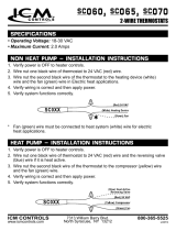
3.4.3 GuidelinesforHaywardHeaters
1. Remove heater service door.
2. Remove factory-installed wire nut between
two (2) red wires labeled "CONNECTION
FOR FIELD INSTALLED CONTROL
SWITCH" (see Figure 11).
3. Wire nut two (2) heater wires from
AquaLink RS P.C. Board to the two (2) red
wires of the heater (see Figure 12).
4. Set the thermostat selector switch to
ON, HIGH, or SPA, and set the heater
thermostat(s) to maximum.
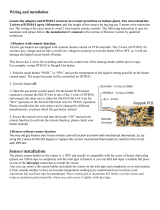
3.4.4 GuidelinesforPentairHeaters
1. Remove the heater service door.
2. Separate the black wires (common) from
each other (see Figure 13).
3. Connect the wires from the Power Center
PCB to the two black wires on the heater
(see Figure 14).
3.4.5 GuidelinesforRaypakHeaters
For the 2-wire/1 function configuration, connect
the orange/black and black/orange wires to one
contact and the yellow/black wire to the other
contact (see Figure 15).
Limit Switch
Factory
Installed
Wire Nut
R
Limit Switch
R
V
OFF ON
BL
Pressure Switch
Figure 11. Hayward Heater Wiring Before
Modification
ON
BL
Limit Switch Limit Switch
R
R
V
OFF
Pressure Switch
Wires to
Power Center
PCB
Figure 12. Hayward Heater Wiring with
AquaLink RS
Figure 13. Pentair Heater Wiring Before
Modification
VIO
BLK
BLK
RED
Figure 14. Pentair Heater Wiring with AquaLink RS
Wires from
Power Center
PCB
VIO
BLK
BLK
RED
Figure 15. Raypak Heater Wiring with AquaLink RS
P7
Terminal
To
AquaLink
RS System
4. Turn the heater toggle switch on, and the
heater thermostat(s) to max.
5. When connecting an AquaLink RS Control
to a Pentair Heater, Pentair requires that
you install the low voltage thermostat wires
in conduit separate from ANY line voltage
wires.

Page 17
3.4.6 GuidelinesforaGasHeaterandaJandy
AE Series Heat Pump/Chiller Installation
NOTE The following steps provide the procedure for
installing a Jandy AE Series Heat Pump.
1. Install a fixed resistor, with a value of 2.2K
Ohms, in the solar sensor terminals #3 and
#4 of the green, 10-pin terminal bar of the
AquaLink RS Power Center (see Figure
16).
2. To run the wires from the Heat Pump
control panel, remove the 5 screws that
attach the service/wiring cover panel to the
heat pump (see Figure 16).
NOTE One end of the wiring reserved for remote
control hook-up of the heat pump is connected
to terminals T5 and T6 on the control panel
printed circuit board (PCB), located on the back
of the control panel.
3. Run the wires from the Heat Pump control
panel through the wiring conduit located on
the outer right hand side of the Heat Pump.
4. Connect the Heat Pump to a standard
relay, then connect the relay to the solar
pump output on the PCB. Set the time to
11:59 PM; at 12:00 AM, the AquaLink
RS will auto-relabel Solar as Heat Pump.
Otherwise, the AquaLink RS will auto-
relabel Solar as Heat Pump within 24 hours.
5. The Solar Button will activate the heat
pump/chiller and the Pool and/or Spa
Heater Buttons will activate the gas heater.
In this manner the pool or spa can be heated
or chilled by the heat pump, the gas heater
or both.
NOTE To program the Heat Pump control panel, refer
to the Jandy AE Series Heat Pump Manual.
4 3 2 1 6 5 4 3 2 1
10 9 8 7 6 5 4 3 2 1
Battery
(9Volt)
®
JANDYAquaLink RS
FILTERPUMPOFF
AIR 79°
06/26/04 MON
6:00 PM
EQUIPMENT ON/OFF
ONETOUCH ON/OFF
MENU / HELP
Gas Heater
Heat Pump/Chiller #1
Note for All Button:
Green- Enabled
Red- On
Gas Heater Connections
Terminals 1 and 2
Fireman's
Switch
From Fusible
Link
To Pressure
Switch
Note for
OneTouch:
LED will not
come on for
Heat Pump
2.2K Ohms Resistor
in Solar Sensor
Terminals for Heat
Pump/Chiller
Heat Pump/Chiller #2
Figure 16. Heater and Heat Pump/Chiller Wiring
Service/Wiring
Cover Panel
Service/Wiring
Cover Panel
Port for Low
Voltage Wires
Standard High
Voltage Relay
Low Voltage Wiring
to Low Voltage Port
on Heat Pump
To Heat Pump #1
To Heat Pump #2
Wireless OneTouch
Transceiver J-box

Page 18
3.5 Temperature Sensors
1. Drill 3/8" hole in pipe between filter
pump and filter and install the Water
Temperature Sensor per instructions
(make certain the o-ring is in place).
2. Install
Air Temperature Sensor outside the
Power Center can, not in direct sunlight and
away from motors and other heat sources.
3. Install Solar Temperature Sensor
(optional) adjacent to solar panels.
NOTE If a solar sensor (or a 2.2K Ohms resistor) is not
installed, the solar button can be labeled and
used as an extra auxiliary.
4. Run the wire to the Power Center, through
the low voltage raceway. Cut off excess
wire. Strip the wire jacket back 6", then
strip each wire ¼". Connect sensor wires to
the green, 10-pin terminal bar (see Figure
17).
3.6 JandyValveActuators
NOTE Mount the JVA's according to the Jandy Valve
Actuator Installation and Operation Manual.
JVA cable is type SJW-A marked water resistant
class 3 cable and does not require conduit.
Knockouts and Heyco fittings are provided in the
Low Voltage Raceway.
1. Route the JVA wire to the Power Center.
Figure 17. Temperature Sensor Wiring for a Pool/Spa
Combination
Water
Temperature
Sensor
Freeze/Air
Temperature
Sensor
Solar
Temperature
Sensor
Green 10-Pin Terminal Bar
10 9 8 7 6 5 4 3 2 1
2. Run the wire through the low voltage
raceway and plug the JVA connectors into
their proper sockets (see Section 6. Power
Center Wiring Diagram). Verify that the
JVA on the suction plumbing is connected
to the Intake JVA Socket, and the discharge
plumbing is connected to the Return JVA
Socket.
NOTE Do not coil the JVA wires inside Power Center.
To shorten the wire, remove the JVA cover
and disconnect the wire. Shorten, strip, and
reconnect.
3. For alternate plumbing configurations the
JVA cam settings can be adjusted as needed.
See the Jandy Valve Actuator Installation
and Operation Manual, Cam Setting Chart
for proper settings.
3.7 Auxiliary Power Centers
AquaLink RS All Button models support one (1)
Auxiliary Power Center.
AquaLink RS OneTouch models support a
maximum of three (3) Auxiliary Power Centers.
1. The auxiliary power centers may be wired
"in series", starting from the Primary Power
Center (solid line) or wired "in parallel"
from the Primary Power Center (dashed
line). See Figure 18.
Primary
Power
Center
or
PureLink
Figure 18. Wiring Multiple Power Centers

Page 19
2. Run four conductor, 22 AWG or larger
cable between the red, 4-pin terminal bars
in each Power Center.
NOTE
• All temperature sensors, heater connections
and the main filter pump must be wired to the
Primary Power Center.
• Never put more than two (2) wires into each
of the pins of the red, 4-pin terminal bar (use
a Jandy Multiplex Board).
• If more than one Auxiliary Power Center is
installed, set the jumpers as shown in Figure
19.
Figure 19. Setting Jumpers for Multiple Auxiliary
Power Centers
Aux. PC #1
(AUX B1 to B8
for RS12, 16,
2/10, 2/14)
W1
W2
Aux. PC #2
(AUX C1 to
C8 for RS24,
2/22)
Aux. PC #3
(AUX D1 to D8 for
RS32, 2/30)
W1
W2
W1
W2
(No Jumpers on the Primary Power Center PCB)
3.8 All Button Control Panel Installation
3.8.1 SingleIndoorControlPanel
1. With the aid of the homeowner, find the
best location for the Control Panel.
2. Open the Indoor Control Panel Assembly by
pressing in on the tab located on the lower
end of the back of the control panel (see
Figure 20). Place the back of the control
panel against the wall. Level the back of
the control panel and mark the three (3)
mounting screw holes and the cable access
hole.
3. Drill ¼" holes at the three (3) mounting
screw marks and insert the plastic anchors.
Drill a 1¼" (min.) to 2" (max.) hole for
cable access.
4. Mount the back of the control panel housing
to the wall and secure in place.
5. Pull the 4-conductor, 22 AWG or larger
cable through the access hole and tie a loose
knot to prevent the cable from slipping back
through the access hole. Strip cable jacket
6", and each individual wire ¼".
6. Remove the red, 4-pin terminal bar from the
control panel PCB. Connect the 4 conductor
cable to the red, 4-pin terminal bar (see
Figure 21). Reconnect the red, 4-pin
terminal bar back to the Control Panel PCB.
Mounting
Screw Holes
4-Conductor Cable
Access Hole
Tab
Figure 20. All Button Control Panel - Back View
Figure 21. All Button Control Panel PCB
4 3 2 1
Red 4-Pin Connector
Green
Yellow
Black
Red
7. Hang the Control Panel front over the two
tabs at the top of the control panel back.
Swing the bottom of the Control Panel front
down and snap into place.

Page 20
3.8.2 MultipleAquaLinkRSAllButton
Control Panel Installation
The AquaLink RS allows each system to support
a maximum of 4 indoor control panels (see Figure
22). The control panels may be wired "in series"
starting from the first control panel (solid lines), or
wired "in parallel" from the AquaLink RS Power
Center (dotted lines), or any combination of the
two. In other words, any number of Indoor control
panels and/or Power Centers can be connected
by means of the red, 4-pin terminal bar in any
combination of "series" or "parallel" wiring.
NOTE Minimum wire size should be 22 AWG. If more
than one control panel is installed, or the length
of run is more than 300 feet, larger wire should
be used.
3.8.3. AquaLinkRSControlPanelJumper
Settings:
Move these jumpers only when installing more
than one control panel on a system (see
Figure 23). The jumpers are used to give each
control panel a unique system address. When
replacing an existing control panel, change the
jumper settings to match those on the one being
replaced.
NOTE If an AquaLink RS Personal Computer Interface
is installed, the AquaLink RS system will
recognize the interface as the fourth All Button
control panel.
3.9 OneTouch Control Panel Installation
3.9.1 Surface Mount OneTouch Installation
1. With the aid of the homeowner, find the
best location for the Control Panel.
2. Place Surface Mount Box in the location
chosen for the Control Panel. Mark the
holes for drilling. Drill 3/16" holes for the
sheet rock anchors and a 1¼" hole for the
4-conductor cable.
3. Run the 4-conductor cable from the Power
Center to the location of the Control Panel
(see Figure 24).
W2
W1
First Controller
Third Controller
W2
W1
Second Controller
W2
W1
Fourth Controller
W2
W1
Yellow
Green
Black
Red
W2
W1
Multiple Control Panels
Jumper
Location
Back of
All Button PCB
Figure 23. Jumper Settings for Multiple All Button
Control Panels
4. Pull the 4-conductor cable through the
hole in the wall and the hole in the Surface
Mount Box. Mount the box to the wall
using the screws provided.
Surface
Mount Box
OneTouch PCB
Faceplate
Sheetrock
Figure 24. OneTouch Surface Mount Installation
RS
TM
RS
TM
RS
TM
RS
TM
Figure 22. Installing Multiple All Button Control
Panels
22 AWG
Minimum
/