Page is loading ...

VC230-AL
In-Vehicle Box PC
User’s Manual
A-545-M-2023
Preliminary
Version
Preliminary
Version

2User's Manual | VC230-AL
Copyright
This publication contains information that is protected by copyright. No part of it may be repro-
duced in any form or by any means or used to make any transformation/adaptation without the
prior written permission from the copyright holders.
This publication is provided for informational purposes only. The manufacturer makes no
representations or warranties with respect to the contents or use of this manual and specifi-
cally disclaims any express or implied warranties of merchantability or fitness for any particular
purpose. The user will assume the entire risk of the use or the results of the use of this docu-
ment. Further, the manufacturer reserves the right to revise this publication and make changes
to its contents at any time, without obligation to notify any person or entity of such revisions or
changes.
Changes after the publication’s first release will be based on the product’s revision. The website
will always provide the most updated information.
© 2020. All Rights Reserved.
Trademarks
Product names or trademarks appearing in this manual are for identification purpose only and
are the properties of the respective owners.
FCC and DOC Statement on Class B
This equipment has been tested and found to comply with the limits for a Class B digital
device, pursuant to Part 15 of the FCC rules. These limits are designed to provide reason-
able protection against harmful interference when the equipment is operated in a residential
installation. This equipment generates, uses and can radiate radio frequency energy and, if not
installed and used in accordance with the instruction manual, may cause harmful interference
to radio communications. However, there is no guarantee that interference will not occur in a
particular installation. If this equipment does cause harmful interference to radio or television
reception, which can be determined by turning the equipment off and on, the user is encour-
aged to try to correct the interference by one or more of the following measures:
• Reorient or relocate the receiving antenna.
• Increase the separation between the equipment and the receiver.
• Connect the equipment into an outlet on a circuit different from that to which the re-
ceiver is connected.
• Consult the dealer or an experienced radio TV technician for help.
Notice:
1. The changes or modifications not expressly approved by the party responsible for com-
pliance could void the user’s authority to operate the equipment.
2. Shielded interface cables must be used in order to comply with the emission limits.

3User's Manual | VC230-AL
Table of Contents
Chapter 1 - Introduction................................................................................................................6
Specifications ......................................................................................................................... 6
Chapter 2 - Hardware Installation ................................................................................................7
Overview .................................................................................................................................. 7
Front Panel ....................................................................................................................... 7
Rear Panel ........................................................................................................................ 7
Top, Bottom, and Sides ................................................................................................... 7
Dimensions ...................................................................................................................... 7
Wall Mount ..............................................................................................................................8
Wall Mount Bracket Installation .....................................................................................8
Assembly ................................................................................................................................ 9
Overview ........................................................................................................................... 9
Bottom Cover ................................................................................................................... 9
Power Board ...................................................................................................................9
Top Cover ....................................................................................................................... 10
Front and Rear Panels ...................................................................................................11
Antenna ..........................................................................................................................12
Board Layout.........................................................................................................................13
System Board .................................................................................................................13
Power Board...................................................................................................................13
LEDs ......................................................................................................................................14
System Board .................................................................................................................14
Power Board...................................................................................................................14
System Memory ...................................................................................................................15
Installing the SO-DIMM Module ...................................................................................15
Jumper Settings (System Board) ........................................................................................16
Clear CMOS (JP3) .........................................................................................................16
Front Panel (JP2) ...........................................................................................................17
Jumper Settings (Power Board)..........................................................................................17
Host Bus Communication .............................................................................................17
SW1 .................................................................................................................................18
24V / 12V Select ............................................................................................................18
POWER ON Delay Switch ..............................................................................................18
POWER OFF Delay Switch .............................................................................................18
POWER ON Delay Time Select .....................................................................................19
POWER OFF Delay Time Select ....................................................................................19
Remote Switch High/Low Active (JP2) .......................................................................19
I/O Ports (System Board) ....................................................................................................20
Graphics Display ............................................................................................................20
USB Ports ....................................................................................................................... 20
RJ45 LAN Ports ............................................................................................................. 21
COM (Serial) Port ..........................................................................................................21
Speaker ...........................................................................................................................22
Front Audio .....................................................................................................................22
12V DC-In .......................................................................................................................23
SATA (Serial ATA) Connectors......................................................................................23
Battery ............................................................................................................................24
SMBus ............................................................................................................................24
Expansion Slots .............................................................................................................25
Installing the Mini PCIe Module ...................................................................................25
Installing Micro SIM Card .............................................................................................26
DIO (GPIO) ...................................................................................................................... 27
CAN Bus (Optional) .......................................................................................................27
GPS Antenna .................................................................................................................. 28
I/O Ports (Power Board) ...................................................................................................... 29
12V DC-Out .....................................................................................................................29
9V~36V In ......................................................................................................................29
MCU Connector .............................................................................................................30
MCU Debug ....................................................................................................................30
Remote Switch ...............................................................................................................31
Chapter 3 - BIOS Settings ...........................................................................................................32
Overview ...............................................................................................................................32
Main .......................................................................................................................................33
Advanced .............................................................................................................................33
CPU Configuration .........................................................................................................34
Video Configuration .......................................................................................................34
Audio Configuration.......................................................................................................35
SATA Configuration .......................................................................................................35
Super IO Configuration .................................................................................................. 36
Vehicle Configuration .................................................................................................... 36
PCI Express Configuration ............................................................................................ 37
Security .................................................................................................................................38
Boot .......................................................................................................................................38
Exit ......................................................................................................................................... 39
Updating the BIOS ................................................................................................................ 39
Notice: BIOS SPI ROM..........................................................................................................39

4User's Manual | VC230-AL
About this Manual
This manual can be downloaded from the website, or acquired as an electronic file included in
the optional CD/DVD. The manual is subject to change and update without notice, and may be
based on editions that do not resemble your actual products. Please visit our website or con-
tact our sales representatives for the latest editions.
Warranty
1. Warranty does not cover damages or failures that arised from misuse of the product,
inability to use the product, unauthorized replacement or alteration of components and
product specifications.
2. The warranty is void if the product has been subjected to physical abuse, improper in-
stallation, modification, accidents or unauthorized repair of the product.
3. Unless otherwise instructed in this user’s manual, the user may not, under any circum-
stances, attempt to perform service, adjustments or repairs on the product, whether in
or out of warranty. It must be returned to the purchase point, factory or authorized ser-
vice agency for all such work.
4. We will not be liable for any indirect, special, incidental or consequencial damages to
the product that has been modified or altered.
About the Package
The package contains the following items. If any of these items are missing or damaged,
please contact your dealer or sales representative for assistance.
• One VC230-AL System
• One Quick Installation Guide
The system and accessories in the package may not come similar to the information listed
above. This may differ in accordance with the sales region or models in which it was sold. For
more information about the standard package in your region, please contact your dealer or
sales representative.
Optional Items
• Wall Mount Kit
• Power Cord
• Internal Power Board for 9~36V power adaption
• CAN BUS Mini PCIe module (MPE-CAN2)
The system and accessories in the package may not come similar to the information listed
above. This may differ in accordance with the sales region or models in which it was sold. For
more information about the standard package in your region, please contact your dealer or
sales representative.

5User's Manual | VC230-AL
Static Electricity Precautions
It is quite easy to inadvertently damage your PC, system board, components or devices even
before installing them in your system unit. Static electrical discharge can damage computer
components without causing any signs of physical damage. You must take extra care in han-
dling them to ensure against electrostatic build-up.
1. To prevent electrostatic build-up, leave the system board in its anti-static bag until you
are ready to install it.
2. Wear an antistatic wrist strap.
3. Do all preparation work on a static-free surface.
4. Hold the device only by its edges. Be careful not to touch any of the components, con-
tacts or connections.
5. Avoid touching the pins or contacts on all modules and connectors. Hold modules or
connectors by their ends.
Safety Precautions
• Use the correct DC / AC input voltage range.
• Unplug the power cord before removing the system chassis cover for installation or
servicing. After installation or servicing, cover the system chassis before plugging in
the power cord.
• There is danger of explosion if battery incorrectly replaced.
• Replace only with the same or equivalent specifications of batteries recommend by
the manufacturer.
• Dispose of used batteries according to local ordinance.
• Keep this system away from humid environments.
• Make sure the system is placed or mounted correctly and stably to prevent the chance
of dropping or falling may cause damage.
• The openings on the system shall not be blocked and shall be kept in distance from
other objects to make sure of proper air ventilation to protect the system from over-
heating.
• Dress the cables, especially the power cord, so they will not be stepped on, in contact
with high temperature surfaces, or cause any tripping hazards.
• Do not place anything on top of the power cord. Use a power cord that has been ap-
proved for use with the system and is compliant with the voltage and current ranges
required by the system’s electrical specifications.
• If the system is to be unused or stored for a long time, disconnect it from the power
source to avoid damage by transient overvoltage.
• If one of the following occurs, consult a service personnel:
- The power cord or plug is damaged.
- Liquid has penetrated the system.
- The system has been exposed to moisture.
- The system is not working properly.
- The system is physically damaged.
• The unit uses a three-wire ground cable which is equipped with a third pin to ground
the unit and prevent electric shock. Do not defeat the purpose of this pin. If your outlet
does not support this kind of plug, contact your electrician to replace the outlet.
• Disconnect the system from the electricity outlet before cleaning. Use a damp cloth
for cleaning the surface. Do not use liquid or spray detergents for cleaning.
Important:
Electrostatic discharge (ESD) can damage your processor, disk drive and other
components. Perform the upgrade instruction procedures described at an ESD
workstation only. If such a station is not available, you can provide some ESD pro-
tection by wearing an antistatic wrist strap and attaching it to a metal part of the
system chassis. If a wrist strap is unavailable, establish and maintain contact with
the system chassis throughout any procedures requiring ESD protection.

6
Chapter 1
INTRODUCTION
User's Manual | VC230-AL
Chapter 1 - Introduction
X Specifications
The specifications listed here may be based on editions that do not
resemble your actual products. Please visit the download page at go.dfi.
com/VC230-AL, or via the QR code to the right for the latest datasheet.
SYSTEM Processor Intel Atom
®
Processor E3900 Series, BGA 1296
x7-E3950 Processor, Quad Core, 2M Cache, 1.6GHz (2.0GHz), 12W
x5-E3940 Processor, Quad Core, 2M Cache, 1.6GHz (1.8GHz), 9W
x5-E3930 Processor, Dual Core, 2M Cache, 1.3GHz (1.6GHz), 6.5W
Memory 1 SODIMM Memory Support up to 8GB
Single Channel DDR3L 1600/1866MHz
BIOS Insyde SPI 64Mbit
GRAPHICS Controller Intel
®
HD Graphics
Display 1 x HDMI
1 x DVI-I
HDMI: resolution up to 3840x2160 @ 60Hz
DVI-I: resolution up to 2560x1600 @ 60Hz
Dual
Displays
HDMI + DVI-I
STORAGE External/In-
ternal
4GB/8GB/16GB/32GB eMMC Onboard (available upon request)
EXPANSION Interface 1 x Full-size Mini PCIe (PCIe/USB/Daul micro SIM)
1 x Full-size Mini PCIe (PCIe/USB/micro SIM)
1 x Half-size mSATA
ETHERNET Controller 2 x Intel® I210AT PCIe (10/100/1000Mbps)
GPS GPS u-blox NEO-M8N onboard
NEO-M8U/L as option to support Dead Reckoning
LED Indicators 1 x Power LED
1 x Storage LED
FRONT I/O Display 1 x HDMI
1 x DVI-I
DIO 8-bit Isolated DIO up to 30V Input
4 x DI
4 x DO
CAN-Bus Supports dual canbus via x1 DB9 port
Buttons 1 x Reset Button
Audio 1 x Speaker Out with Dual 5w Amp
REAR I/O Ethernet 2 x GbE (RJ-45)
Serial 1 x RS-232/422/485 (DB-9)
USB 2 x USB 2.0 (type A)
2 x USB 3.0
Antennas 1 x SMA Antenna Hole
1 x FME Antenna Hole
WATCHDOG
TIMER
Output &
Interval
System Reset, Programmable via Software from 1 to 255 Seconds
POWER Type Wide Range 9~36V with Vehicle Control
Connector 3-pin Terminal Block (VCC/IGN/GND)
OS SUPPORT Windows 10 64-bit
Linux
CentOS 7
MECHANISM Construction Aluminum + SPGC Metal
Mounting Wall/VESA Mount
Dimensions 180mm x 50mm x 121.2mm (W x H x D)
ENVIRONMENT Operating Temperature: -40 to 70°C
Storage Temperature: -40 to 85°C
COMPLIANCE Shock MIL-STD-810G 516.6
Vibration MIL-STD 810G 514.6C-3
Certifications CE/FCC Class B/E-mark (E13)

7
Chapter 2
HARDWARE INSTALLATION
User's Manual | VC230-AL
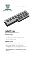
Chapter 2 - Hardware Installation
X Overview
Front Panel
Rear Panel
Top, Bottom, and Sides
Dimensions
SSD LED
HDMIDVI
CAN BUS
Power LED
& Reset
Speaker
GPIO
LAN 1USB 2.0
USB 3.0Remote
Switch
Antenna
Hole
COM 1GPS Antenna LAN 2
Vehicle Power
and Ignition
Top
Bottom

8
Chapter 2
HARDWARE INSTALLATION
User's Manual | VC230-AL
X Wall Mount
Wall Mount Bracket Installation
The wall mount kit containing two mount-
ing brackets — purchased as optional items
— can be attached to the bottom of the
system for mounting onto desired locations,
such as walls, stands, or shelves. Locate
the mounting holes on the bottom of the
system as shown in the photo. Screw on
the two brackets onto the system with four
screws as illustrated below.
The pre-drilled mounting holes on the brackets allow for different wall mount distances.
182.20
121.20
25.00
46.00
41.50
192.00
182.20
121.20
25.00
46.00
41.50
192.00
Bottom

9
Chapter 2
HARDWARE INSTALLATION
User's Manual | VC230-AL
X Assembly
Overview
The system is assembled in the following procedure. To disassemble, please carry out the pro-
cedure in the reversed order.
1. Attach the front and rear panels to the system board.
2. Attach the top cover to the assembly.
3. Attach power board brackets and power board.
4. Attach the bottom cover.
The power board sits parallel to the system board, and may hinder the installation of particular
internal I/O interfaces. Please remove the power board first to access the internal I/O.
Bottom Cover
The internal I/O of the system is mainly accessed via the bottom side. The bottom metal cover
is secured onto the chassis with 14 F3*5 zinc-coated screws located at both sides and on the
bottom. Use a Phillips screwdriver to unscrew them.
For particular models, there is a
memory heatsink attached to the
inside of the bottom cover. When
installing, orient the bottom cover
so that the heatsink sits right on top
of the memory.
x14
SideSide
Bottom
Memory
Power Board
The power board is secured in the chassis via two brackets installed onto the front and the rear
panel. The mounting screw holes are as shown in the photo. Locate and align the mounting
holes, and screw the brackets to the chassis tight. Please make sure the brackets are oriented
correctly as illustrated. The two brackets shall perfectly mirror each other. The handles shall be
closer to the SO-DIMM socket on the mother board.
Mounting Screw Holes
x4
Front Panel

10
Chapter 2
HARDWARE INSTALLATION
User's Manual | VC230-AL
Top Cover
The top cover is secured onto the system board's brass stand-offs at four corners.
x4
Front Panel
Rear Panel
Align the four mounting holes of the power board with those on the bracket as indexed. The
I/O interfaces of the power board shall be facing up and away from the motherboard. Place the
board onto the brackets and then screw in the four M3*6 spring screws tight as shown below.
Bottom Up
Bottom Up
handle
Front Panel
Bottom Up
Bottom Up
handle
Rear Panel
180°
A
B
A
B
A
B
B
A
A
B
A
B
The result shall resemble the photo below. Connect the cables to the power board as neces-
sary.
X Assembly
Front Panel
Front Panel
x4

11
Chapter 2
HARDWARE INSTALLATION
User's Manual | VC230-AL
To install the top cover, we suggest that the top cover be placed on a worksufrace with the
inside facing upward. The location of the stand-offs and the top cover screw holes are as illus-
trated below. Orient the assembly of system board and panels so that ...
After the top cover is correctly attached to
the system board and panels, screw on the
four F3*5 zinc-coated screws (A) at four
corners, and a M3*6 spring screw (B) for
making sure the CPU contacts the inter-
face metal.
X Assembly
1. the CPU on the system board sits right
on top of the interface metal on the
inside of the top cover;
2. the brass stand-offs on the system
board align with the screw holes on
the top cover;
3. the front and rear panels sink into the
indentations along the long edges of
the top cover.
Front Panel
Front Panel
Front and Rear Panels
The front and rear panels are secured onto the system board via the
I/O stand-offs and screws as shown below.
Front Panel
Rear Panel
A
A
A
A
B
x4 x1

12
Chapter 2
HARDWARE INSTALLATION
User's Manual | VC230-AL
Antenna
Besides the GPS antenna, there is an additional antenna hole reserved on the front panel and
by default covered by a metal bracket. Please remove the metal bracket by unscrewing the two
zinc-coated screw prior to installing an antenna.
Before installing the antenna, please make sure that the following safety cautions are well-
attended.
1. Make sure the PC and all other peripheral devices connected to it has been powered
down.
2. Disconnect all power cords and cables.
Connect the internal cable to the board's antenna connector, screw the antenna connector
through the antenna hole on the front panel with washers and nuts, and screw on the antenna
as illustrated below.
FME Antenna hole
with bracket
GPS Antenna
(SMA)
Front Panel
x2
Antenna ConnectorCableBoard Connector NutWasher
Chassis Wall
Antenna
X Assembly

13
Chapter 2
HARDWARE INSTALLATION
User's Manual | VC230-AL
Important:
Electrostatic discharge (ESD) can damage your board, processor,
disk drives, add-in boards, and other components. Perform instal-
lation procedures at an ESD workstation only. If such a station is
not available, you can provide some ESD protection by wearing an
antistatic wrist strap and attaching it to a metal part of the system
chassis. If a wrist strap is unavailable, establish and maintain con-
tact with the system chassis throughout any procedures requiring
ESD protection.
X Board Layout
1
1
1
1
6
5
2
1
10
1
210
1
2
1
1
1
1
2
9
10
DDR3L_ SODIMM
1
2
3
4
5
6
7
8
9
10
11
12
13
14
17
20
23
24
25
26
27
28
29
30
31
32 33
21 22
15
18
19
16
System Board Power Board
DIO (GPIO)
Reset Button
LED1
LED3
12V DC In
VGA/DVI-I
HDMI
LED2
Speaker
Front Audio
COM1
USB 7 (USB 2.0)
USB 6 (USB 2.0)
Micro SIM (via Mini PCIe 1)
Micro SIM (via Mini PCIe 1)
Micro SIM (via Mini PCIe 2)
USB 1/2 (USB 3.0)
SPI Flash BIOS
SMBus
LAN1
USB 1/2 (USB 2.0)
USB 3/4 (USB 2.0)
LAN2
Antenna
Mini PCIe 2
ST-Link / SWD
MCU Debug
Remote Switch
JP2
12V DC Out
9V~36V In
JP4
JP3
SW1
LED1
LED2
1
2
3
4
5
6
7
8
9
10
11
12
13
14
15
16
17
18
19
20
21
22
23
24
25
1
2
3
4
5
6
7
8
9
10
11
Buzzer
JP3
SATA
SATA Power
Battery
JP2
Mini PCIe 1
mSATA
26
27
28
29
30
31
32
33
1
ON
2 3 4 5 6 7 8
1
2
3
4
9
5
6
7 8
1011
11
1
1
1
1

14
Chapter 2
HARDWARE INSTALLATION
User's Manual | VC230-AL
1
1
1
1
6
5
2
1
10
1
210
1
2
1
1
1
1
2
9
10
DDR3L_ SODIMM
Important:
When the Standby Power LED lights up, it indicates that there is power on the
system board. Power-off the PC then unplug the power cord prior to installing any
devices. Failure to do so will cause severe damage to the motherboard and com-
ponents.
X LEDs
Power LED
Standby Power LED
Power LED SSD LED
SSD LED
Rear Panel
System Board Power Board
1
ON
2 3 4 5 6 7 8
11
1
1
1
1
1
ON
2 3 4 5 6 7 8
11
1
1
1
1
LED2 LED1
LED2 (Green): R/W LED
LED1 (Red): Debug LED for the MCU

15
Chapter 2
HARDWARE INSTALLATION
User's Manual | VC230-AL
1
1
1
1
6
5
2
1
10
1
210
1
2
1
1
1
1
2
9
10
DDR3L_ SODIMM
• One SO-DIMM Memory up to 8GB
• Single Channel DDR3L 1600/1866MHz
X System Memory
Features
DDR3L
The system board supports the following memory interface.
Single Channel (SC)
Data will be accessed in chunks of 64 bits from the memory channels.
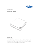
Installing the SO-DIMM Module
Before installing the memory module, please make sure that the following safety cautions are
well-attended.
1. Make sure the PC and all other peripheral devices connected to it has been powered
down.
2. Disconnect all power cords and cables.
3. Locate the SO-DIMM socket on the system board
4. Make sure the notch on memory card is aligned to the key on the socket.
Notch
Retention Notch
Key
Socket Top View
DDR3 SO-DIMM
Retention Clip
45°
Step 1
Step 2
Step 3

16
Chapter 2
HARDWARE INSTALLATION
User's Manual | VC230-AL
Please follow the steps below to install the memory card into the socket.
Step 1:
Insert the memory card into the
slot while making sure 1) the
notch and the key are aligned,
and 2) the non-connector end
rises approximately 45 degrees
horizontally. Press the card firmly
into the socket while applying and
maintaining even pressure on both
ends.
Step 2:
Press the end of the card far from
the socket down while making
sure the retention notch and the
clip align as indicated by the dot-
ted line in the illustration. If the
retention notch and the clip do not
align, please remove the card and
re-insert it. Press the card all the
way down.
Step 3:
The clips snap automatically and
abruptly to the retention notches
of the card sounding a distinctive
click, and lock the card in place.
Inspect that the clip sits in the
notch. If not, please pull the clips
outward, release and remove the
card, and mount it again.
Notch
Retention Notch
Key
Socket Top View
DDR3 SO-DIMM
Retention Clip
45°
Step 1
Step 2
Step 3
X System Memory
X Jumper Settings (System Board)
Clear CMOS (JP3)
If any anomaly of the followings is encountered —
a) CMOS data is corrupted;
b) you forgot the supervisor or user password;
c) failure to start the system due to BIOS mis-configuration
— it is suggested that the system be reconfigured with default values stored in the ROM BIOS.
To load the default values stored in the ROM BIOS, please follow the steps below.
1. Power-off the system and unplug the power cord.
2. Put a jumper cap on JP3’s pin 2 and pin 3. Wait for a few seconds and set JP3 back to
its default setting, i.e. jumper cap on pin 1 and pin 2.
3. Plug the power cord and power-on the system.
2-3 On: Clear CMOS 1-2 On: Normal (default)
1
1
1
1
6
5
2
1
10
1
210
1
2
1
1
1
1
2
9
10
DDR3L_ SODIMM
1
1
1
1
6
5
2
1
10
1
210
1
2
1
1
1
1
2
9
10
DDR3L_ SODIMM
3
1
2
3
1
2
JP3

17
Chapter 2
HARDWARE INSTALLATION
User's Manual | VC230-AL
Front Panel (JP2)
1
1
1
1
6
5
2
1
10
1
210
1
2
1
1
1
1
2
9
10
DDR3L_ SODIMM
1
1
1
1
6
5
2
1
10
1
210
1
2
1
1
1
1
2
9
10
DDR3L_ SODIMM
Pin Assignment
1 Power Button
2 GND
3 N.C.
Front Panel Pin Assignment
JP2
Power Switch
This jumper is used to power on or off the system.
X Jumper Settings (Power Board)
1
ON
2 3 4 5 6 7 8
11
1
1
1
1
1
ON
2 3 4 5 6 7 8
11
1
1
1
1
JP4 JP3
Host Bus Communication
The two jumpers are for selecting the signals for the bus used for the system to monitor the
power board. Both JP4 and JP3 shall be set to the same settings, either 1-2 On or 2-3 On as
illustrated below.
2-3 On: TX/RX UART (default) 1-2 On: Reserved
3
1
2
3
1
2
X Jumper Settings (System Board)

18
Chapter 2
HARDWARE INSTALLATION
User's Manual | VC230-AL
SW1 24V / 12V Select
The eight switches are for configuring power related setups detailed in the following sections.
X Jumper Settings (Power Board)
Important:
Power-off the system and then unplug the power cord prior to setting the switch-
es. Failure to do so will cause severe damage to the system and components.
1
ON
2 3 4 5 6 7 8
11
1
1
1
1
1
ON
2 3 4 5 6 7 8
11
1
1
1
1
1
ON
2 3 4 5 6 7 8
11
1
1
1
1
1
ON
2 3 4 5 6 7 8
11
1
1
1
1
1
ON
2 3 4 5 6 7 8
11
1
1
1
1
1 Output Voltage
On 12V (default)
Off 24V
2 Delay On/Off
On On, delay duration defined by 4 and 5
Off Off, delay = 3 seconds by default
3 Delay On/Off
On On, delay duration defined by 6, 7, and 8
Off Off, delay = 0 second by default
POWER ON Delay Switch
POWER OFF Delay Switch

19
Chapter 2
HARDWARE INSTALLATION
User's Manual | VC230-AL
X Jumper Settings (Power Board)
X SW1
POWER ON Delay Time Select
POWER OFF Delay Time Select
1
ON
2 3 4 5 6 7 8
11
1
1
1
1
1
ON
2 3 4 5 6 7 8
11
1
1
1
1
5 4 Delay Duration
On On 10 seconds
On Off 30 seconds
Off On 1 miniute
Off Off 5 minutes
8 7 6 Delay Duration
On On On 30 seconds
On On Off 1 minute
On Off On 3 minutes
On Off Off 5 minutes
Off On On 10 minutes
Off On Off 15 minutes
Off Off On 30 minutes
Off Off Off 1 hour
1
ON
2 3 4 5 6 7 8
11
1
1
1
1
1
ON
2 3 4 5 6 7 8
11
1
1
1
1
JP2
Remote Switch High/Low Active (JP2)
JP2 is for selecting the remote switch signal using high or low level voltage.
2-3 On: Low Active 1-2 On: High Active (default)
3
1
2
3
1
2
X Jumper Settings (Power Board)

20
Chapter 2
HARDWARE INSTALLATION
User's Manual | VC230-AL
X I/O Ports (System Board)
Graphics Display
HDMI
The HDMI port which carries both digital audio and video signals is used to connect a LCD
monitor or digital TV that has the HDMI port.
DVI-I Port
The DVI-I port is used to connect a LCD monitor. This port supports DVI-D signal only. Connect
the display device’s cable connector to the DVI-I port. After plugging the cable connector into
the port, gently tighten the cable screws to hold the connector in place.
VGA (Optional)
The VGA port is used for connecting a VGA monitor. Connect the monitor’s 15-pin D-shell cable
connector to the VGA port. After you plug the monitor’s cable connector into the VGA port, gen-
tly tighten the cable screws to hold the connector in place.
Driver Installation
Install the graphics driver. Please refer to Chapter 4 for more information.
HDMI
HDMI
VGA / DVI
VGA / DVI
USB Ports
USB allows data exchange between your computer and a wide range of simultaneously acces-
sible external Plug and Play peripherals. The system board is equipped with multiple USB Type
A ports at the front panel — two USB 3.0 and two USB 2.0 ports — along with four internal USB
2.0 pin-header ports.
Wake-On-USB Keyboard/Mouse
The Wake-On-USB Keyboard/Mouse function allows you to use a USB keyboard or USB mouse
to wake up a system from the S3 (STR - Suspend To RAM) state.
BIOS Setting
Configure USB devices in the Advanced menu (“USB Configuration” submenu) of the BIOS. Re-
fer to Chapter 7 for more information.
USB 2 (USB 3.0)
USB 1 (USB 3.0)
Rear Panel
Front Panel
1
1
1
1
6
5
2
1
10
1
210
1
2
1
1
1
1
2
9
10
DDR3L_ SODIMM
1
1
1
1
6
5
2
1
10
1
210
1
2
1
1
1
1
2
9
10
DDR3L_ SODIMM
USB 6 (USB 2.0)
USB 7 (USB 2.0)
1
1
1
1
6
5
2
1
10
1
210
1
2
1
1
1
1
2
9
10
DDR3L_ SODIMM
USB 1/2
(USB 2.0)
USB 3/4
VCC
-Data
+Data
GND
Key
VCC
-Data
+Data
GND
N.C.
2 10
1
/