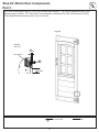
KidKraft Kingsbridge Wooden Swing Set / Playset Assembly Instruction
- Type
- Assembly Instruction

INSTALLATION AND OPERATING INSTRUCTIONS
KINGSBRIDGE – F25010
9405010
Table of Contents
Warnings and Safe Play Instructions .....pg. 2
Protective Surfacing Guidelines .........pg. 3
Instructions for Proper Maintenance ...... pg. 4
About Our Wood – Limited Warranty .....pg. 5
Keys to Assembly Success .............pg. 6
Part ID ...........................pg. 8-18
Step-By-Step Instructions ..........pg. 19-112
Installation of I.D./Warning Plaque ..... pg. 113
Registration .................... Last Page
To reduce the risk of serious injury or death, you must read and
follow these instrucons. Keep and refer to these instrucons
oen and give them to any future owner of this play set.
Manufacturer contact informaon provided below.
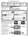
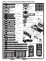
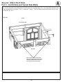
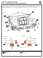
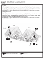
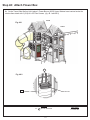
OBSTACLE FREE SAFETY ZONE -30’ 6” x 29’8” area requires Protecve Surfacing. See page 3.
MAXIMUM VERTICAL FALL HEIGHT - 6’ 7”
CAPACITY - 14 Users Maximum, Ages 3 to 10; Weight Limit 110 lbs. (49.9 kg) per child.
RESIDENTIAL HOME USE ONLY. Not intended for public areas such as mul-unit residences, schools, churches,
nurseries, day cares or parks.
Warning. Only for domesc use.
WARNING
18-24 Hrs*
Two person
assembly
17'-8"
29'-8"
30'-6"
18'-6"
*Actual assembly time may vary
Rev 07/08/2019
KidKraft, Inc.
4630 Olin Road
Dallas, Texas 75244 USA
1.800.933.0771
972.385.0100
For online parts replacement visit
https://parts.kidkraft.com/
KidKraft Netherlands BV
Olympisch Stadion 29
1076DE Amsterdam
The Netherlands
+31 20 305 8620 M-F from 09:00 to 17:30
(GMT+1)
For online parts replacement visit
https://parts.kidkraft.eu/

2
Warnings and Safe Play Instructions
CONTINUOUS ADULT SUPERVISION REQUIRED. Most serious injuries and deaths on playground equipment have occurred
while children were unsupervised! Our products are designed to meet mandatory and voluntary safety standards. Complying
with all warnings and recommendations in these instructions will reduce the risk of serious or fatal injury to children using
this play system. Go over the warnings and safe play instructions regularly with your children and make certain that they
understand and follow them. Remember on-site adult supervision is required for children of all ages.
SERIOUS HEAD INJURY HAZARD
Installation over concrete, asphalt, dirt, grass, carpet
and other hard surface creates a risk of serious injury
or death from falls to the ground. Install and maintain
shock absorbing material under and around play-set as
recommended on page 3 of these instructions.
COLLISION HAZARD
Place play-set on level ground at least 2m from any
obstruction such as a garage or house, fences, poles,
trees, sidewalks, walls, landscape timbers, rocks,
pavement, planters, garden borders, overhanging
branches, laundry lines, and electrical wires. (See
OBSTAC
LE FREE SAFETY ZONE on cover)
CHOKING HAZARD/SHARP EDGES & POINTS
Adult assembly required. This product contains small
parts and parts with sharp edges and points. Keep parts
away from children until fully assembled.
WARNING LABEL
Owners shall be responsible for maintaining the legibility
of the warning labels.
STRANGULATION HAZARD
,seni lsehtolc ,sepor ht iw yalp ot nerdl ihc wol la REVEN •
pet leashes, cables, chains or cord-like items when using
this play-set or to attach these items to play-set.
ponchos, hoods, scarves, capes, necklaces, items with
draw-strings, cords or ties when using this play-set.
ste mleh trops ro ekib raew ot nerdl ihc wol la REVEN •
when using this play-set.
Failure to prohibit these items, even helmets with chin
straps, increases the risk of serious injury and death to
children from entanglement and strangulation.
TIP OVER HAZARD
Choose a level location for the equipment. This can reduce
the likelihood of the play set tipping over and loose-fill
surfacing materials washing away during heavy rains.
DO NOT allow children to play on the play-set until the
assembly is complete and the unit is properly anchored.
Never add extra length to chain or rope. The chains or ropes
provided are the maximum length designed for the swinging
element(s).
WARNING
eeS . t es-ya l p ruoy fo sno i t a t imi l y t i capac evresbO
front cover.
gn i so l cne t oo f l l u f dna gn i t t fi l l ew h t iw ne r d l i hc sse rD
footwear.
retnec eht ni thgiew l luf r i eht ht iw t is ot nerdl ihc hcaeT
of the swing seat to prevent erratic swing motion or
falling off.
, gn i ss im ; doo w dekcarc ro nekorb , dere t n i l ps rof kcehC
loose, or sharp edged hardware. Replace, tighten and or
sand smooth as required prior to playing.
n i ahc , s r edda l epor , sepor gn i bmi l c dednepsus t ah t y f i r eV
or cable are secured at both ends and cannot be looped
back on itself as to create an entanglement hazard.
r eh t o dna ed i l s eh t kcehc , syad t oh ro dna ynnus nO
plastic rides to assure that they are not very hot as to
cause burns. Cool hot slide and rides with water and wipe
dry prior to using.
r aewt oo f l eeh ro eo t nepo r aew o t ne rd l i hc wo l l a t on oD
like sandals, flip–flops or clogs.
dniheb ,neewteb , tnorf ni ,klaw ot nerdl ihc wol la ton oD
or close to moving rides.
pool ro sepor ro sniahc gniws tsiwt nerdl ihc tel ton oD
them over the top support bar. This may reduce the
strength of the chain or rope and cause premature failure.
.noi tom ni era yeht el ihw sedi r f fo teg nerdl ihc tel ton oD
. t ew s i t i nehw t nemp i uqe no gn i bmi l c t imr ep t on oD
a n i t nem p i uqe f o esu r o ya l p hguo r t imr ep t on oD
manner for which it was not intended. Standing on or
jumping from the roof, elevated platforms, swings,
climbers, ladders or slide can be dangerous.
.staes ro sedi r ytp m e gniws ot nerdl ihc wol la ton oD
ro tsrfi daeh ed i l s nwod og o t ne rd l i hc wo l l a t on oD
run up slide.
WARNING
– Safe Play Instructions
Orientate slide such that it gets the least amount of exposure
to the sun.

3
One of the most important things you can do to reduce the likelihood of serious head injuries is to install shock-absorbing
protective surfacing under and around your play equipment. The protective surfacing should be applied to a depth that is suitable
for the equipment height in accordance with ASTM F1292. There are different types of surfacing to choose from; whichever
product you select, follow these guidelines:
Loose-Fill Materials
• Maintain a minimum depth of 9 inches of loose-fill materials such as wood mulch/chips, engineered wood fiber (EWF), or
shredded/recycled rubber mulch for equipment up to 8 feet high; and 9 inches of sand or pea gravel for equipment up to 5 feet
high. NOTE: An initial fill level of 12 inches will compress to about a 9-inch depth of surfacing over time. The surfacing will also
compact, displace, and settle, and should be periodically raked and refilled to maintain at least a 9-inch depth.
• Use a minimum of 6 inches of protective surfacing for play equipment less than 4 feet in height. If maintained properly, this
should be adequate. (At depths less than 6 inches, the protective material is too easily displaced or compacted.)
NOTE: Do not install home playground equipment over concrete, asphalt, or any other hard surface. A fall onto a hard surface
can result in serious injury to the equipment user. Grass and dirt are not considered protective surfacing because wear and
environmental factors can reduce their shock absorbing effectiveness. Carpeting and thin mats are not adequate protective
surfacing. Ground level equipment -- such as a sandbox, activity wall, playhouse or other equipment that has no elevated play
surface -- does not need any protective surfacing.
• Use containment, such as digging out around the perimeter and/or lining the perimeter with landscape edging. Don’t forget to
account for water drainage.
• Periodically rake, check and maintain the depth of the loose-fill surfacing material. Marking the correct depth on the play
equipment support posts will help you to see when the material has settled and needs to be raked and or replenished. Be sure to
rake and evenly redistribute the surfacing in heavily used areas.
• Do not install loose fill surfacing over hard surfaces such as concrete or asphalt.
Poured-In-Place Surfaces or Pre-Manufactured Rubber Tiles
You may be interested in using surfacing other than loose-fill materials - like rubber tiles or poured-in-place surfaces.
• Installations of these surfaces generally require a professional and are not “do-it yourself” projects.
• Review surface specifications before purchasing this type of surfacing. Ask the installer/manufacturer for a report showing that
the product has been tested to the following safety standard: ASTM F1292 Standard Specification for Impact Attenuation of
Surfacing Materials within the Use Zone of Playground Equipment. This report should show the specific height for which the
surface is intended to protect against serious head injury. This height should be equal to or greater than the fall height - vertical
distance between a designated play surface (elevated surface for standing, sitting, or climbing) and the protective surfacing
below - of your play equipment.
• Check the protective surfacing frequently for wear.
Placement
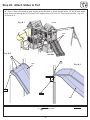
Proper placement and maintenance of protective surfacing is essential. Refer to diagram on front cover. Be sure to;
• Extend surfacing at least 2m from the equipment in all directions.
• For to-fro swings, extend protective surfacing in front of and behind the swing to a distance equal to twice the height of the top bar
from which the swing is suspended.
• For tire swings, extend surfacing in a circle whose radius is equal to the height of the suspending chain or rope, plus 6 feet in all
directions.
From the CPSC Outdoor Home Playground Safety Handbook. At http://www.playgroundregs.com/resources/CPSC%20324.pdf
Protective Surfacing - Reducing Risk of Serious Head Injury From Falls.
2H 2H
H
Denotes Use Zone with Protective Surfacing
Use Zone for Single-Axis Swings
6 ft.
6 ft.
6 ft.
6 ft.
Denotes Use Zone with Protective Surfacing
Use Zone for Multi-Axis Swings
6 ft. 6 ft.
6 ft.
L

4
Instructions for Proper Maintenance
HARDWARE:
Check metal parts for rust. If found,
sand and repaint using a non-lead
paint complying with 16 CFR 1303.
Inspect and tighten all hardware. On
wood assemblies DO NOT OVER-
TIGHTEN as to cause crushing and
splintering of wood.
Check for sharp edges or protruding screw threads, add
washers if required.
SHOCK ABSORBING SURFACING:
Check for foreign objects. Rake and check depth of loose
fill protective surfacing materials to prevent compaction
and maintain appropriate depth. Replace as necessary.
(See Protective Surfacing, page 3)
GROUND STAKES (ANCHORS):
Check for looseness, damage or deterioration. Should
firmly anchor unit to ground during use. Re-secure and
or replace, if necessary.
SWING HANGERS:
Check that bolts are secure and tight. Quick clips should
be completely closed and threaded clips screwed tight.
If squeaking occurs lubricate bushings with oil or WD-40®.
SWINGS, ROPES AND RIDES:
Reinstall if removed during cold season. Check all
moving parts including swing seats, ropes, chains and
attachments for wear, rust and other deterioration.
Replace as needed.
Check that ropes are tight, secure at both ends and
cannot loop back as to create an entrapment.
WOOD PARTS:
Check all wood members for deterioration, structural
damage and splintering. Sand down splinters and replace
deteriorated wood members. As with all wood, some
checking and small cracks in grain is normal.
Unprotected, they will appear weathered over time.
Periodic application of an exterior water repellent or stain
(water-based) will help improve appearance and life.
Your KidKraft Play System is designed and constructed of quality materials with your child’s safety in mind. As with all outdoor
products used by children, it will weather and wear. To maximize the enjoyment, safety and life of your Play Set, it is important
that you, the owner, properly maintain it.
Check the following at the beginning of the play season:
HARDWARE:
Inspect for tightness. Must be firmly against, but not
crushing the wood. DO NOT OVER-TIGHTEN.
This will cause splintering of wood.
Check for sharp edges or protruding screw threads.
Add washers if required.
SHOCK ABSORBING SURFACING:
Rake and check depth of loose fill protective surfacing
materials to prevent compaction and maintain appropriate
depth. Replace as necessary.
(See Protective Surfacing, page 3)
Check twice a month during play season:
SWING HANGERS:
Check that they are secure and orientated correctly. Hook
should rotate freely and perpendicular to support beam.
If squeaking occurs lubricate bushings with oil or WD-40®.
SWINGS AND RIDES:
Check swing seats, all ropes, chains and attachments for
fraying, wear, excessive corrosion or damage.
Replace if structurally damaged or deteriorated.
Check once a month during play season:
SWINGS AND RIDES:
To prolong their life, remove swings and store inside
when outside temperature is below 32°F/0°C. Below
freezing, plastic parts may become more brittle.
SHOCK ABSORBING SURFACING:
Rake and check depth of loose fill protective surfacing
materials to prevent compaction and maintain appropriate
depth. Replace as necessary.
(See Protective Surfacing, page 3)
Check at the end of the play season:
If you dispose of your play set: Please disassemble and dispose of your unit so that it does not create any unreasonable hazards
at the time it is discarded. Be sure to follow your local waste ordinances.
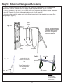
Use an extra
Flat Washer
If Bolt protrudes
beyond T-Nut

5
About Our Wood
KidKraft Premium Play Systems uses only premium playset lumber, ensuring the safest product for your children’s use. Although we
take great care in selecting the best quality lumber available, wood is still a product of nature and susceptible
to weathering which can change the appearance of your set.
What causes weathering? Does it affect the strength of my Play System?
One of the main reasons for weathering is the effects of water (moisture); the moisture content of the wood at the surface is
different than the interior of the wood. As the climate changes, moisture moves in or out of the wood, causing tension which can
result in checking and or warping. You can expect the following due to weathering. These changes will not affect the strength of
the product:
1. Checking is surface cracks in the wood along the grain. A post (4” x 4”) will experience more checking than a board (1” x 4”)
because the surface and interior moisture content will vary more widely than in thinner wood.
2. Warping results from any distortion (twisting, cupping) from the original plane of the board and often happens from rapid
wetting and drying of the wood.
3. Fading happens as a natural change in the wood color as it is exposed to sun-light and will turn a grey over time.
How can I reduce the amount of weathering to my Play System?
At the factory we have coated the wood with a water repellent or stain. This coating decreases the amount of water absorption
during rain or snow thus decreasing the tension in the wood. Sunlight will break down the coating, so we recommend applying a
water repellent or stain on a yearly basis (see your local stain and paint supplier for a recommended product).
Most weathering is just the normal result of nature and will not affect safe play and enjoyment for your child. However if you are
concerned that a part has experienced a severe weathering problem please call our consumer relations department for further assistance.
Complete and mail registration card to receive important product notifications and assure prompt
warranty service.
5 Year Limited Warranty
KidKraft warrants that this product is free from defect in materials and workmanship for a period of one
year from the original date of purchase. In addition, lumber is warranted for 5 years against structural
failure due to rot and insect damage. All other parts, such as hardware, swings, rides, accessories, and
slides carry a one-year warranty only.
This warranty applies to the original owner and registrant and is non-transferable.
Regular maintenance is required to assure the integrity of your Play System. This warranty does not
cover any inspection cost.
This Limited Warranty does not cover:
• Labor for replacement of any defective item(s);
•Incidental or consequential damages;
• Cosmetic defects which do not affect performance or integrity;
•Vandalism; improper use or installation; acts of nature;
•
Minor twisting, warping, checking, or any other natural occurring properties of wood that do not
affect performance or integrity.
KidKraft products have been designed for safety and quality. Any modifications made to the original
product could damage the structural integrity of the unit leading to failure and possible injury.
Kidkraft cannot assume any responsibility for modified products. Furthermore, modification voids
any and all warranties.
This product is warranted for RESIDENTIAL USE ONLY. Under no circumstance should a
KidKraft Play System be used in public settings such as schools, churches, playgrounds, parks, day
cares and the like. Such use may lead to product failure and potential injury. Any and all public use
will void this warranty.
KidKraft disclaims all other representations and warranties of any kind, express or implied.
This Warranty gives you specific legal rights. You may have other rights as well which vary from state to state or
province to province. This warranty excludes all consequential damages, however, some states do not allow the
limitation or exclusion of consequential damages, and therefore this limitation may not apply to you.

6
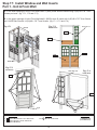
Part Identication Key
On each page, you will nd the parts
and quantities required to complete
the assembly step illustrated on that
page. Here is a sample.
Key Number: The rst two digits
represent the step number. The third
digit represents the piece. Note that if
the part is used in multiple steps then
the number only reects the rst step
it is used in.
Symbols
Throughout these instructions symbols are provided as important reminders for proper and safe assembly.
Proper Hardware Assembly
Lag screws require drilling pilot
holes to avoid splitting wood. Only a
at washer is required. For ease of
installation liquid soap can be used
on all lag-type screws.
For bolts, tap T-Nut into hole with
hammer. Insert the hex bolt through
lock washer rst then at washer
then hole. Because the assemblies
need to be squared do not completely
tighten until instructed. Pay close
attention to diameter of the bolts.
5/16” is slightly larger than 1/4”.
Note: Wafer head bolts with blue lock
tight or a bolt with a Ny-Lok nut do
NOT require a lock washer.
Once the assembly is tightened, watch for exposed
threads. If a thread protrudes from the T-Nut, remove
the bolt and add washers to eliminate this condition.
Extra washers have been provided for this purpose.
This identies information that requires
special attention. Improper assembly could
lead to an unsafe or dangerous condition.
Where this is shown, 2 or 3
people are required to safely
complete the step. To avoid
injury or damage to the
assembly make sure to
get help!
Check that assembly is square
before tightening bolts.
Use a measuring tape to
assure proper location.
Check that set or assembly is properly level
before proceeding.
Pre-drill a pilot hole
before fastening screw
or lag to prevent
splitting of wood.
This indicates time to tighten bolts, but
not too tight! Do not crush the wood.
This may create splinters and cause
structural damage.
Use
Help
Use
Help
Measure
Distance
Square
Assembly
Use
Level
Pre-drill 1/8” & 3/16” Bit
Tighten
Bolts
No Yes
CAUTION – Protrusion Hazard
Keys to Assembly Success
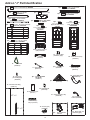
Tools Required
• Tape Measure
• Carpenters Level
• Carpenters Square
• Claw Hammer
• Standard or Cordless Drill
• #1, #2 & #3 Phillips
or Robertson Bits
or Screwdriver
• Ratchet with extension
(1/2” & 9/16” sockets)
• Open End Wrench
(7/16”, 1/2” & 9/16”)
• Adjustable Wrench
• 1/8” & 3/16” Drill Bits
• Pencil
• 3/16” Hex Key
• 8’ Step Ladder
• Safety Glasses
• Adult Helpers
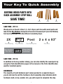
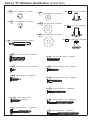
Quantity Key Number Part Description,
Part Size
2X 012 Post 2 x 4 x 83”
Use an extra
Flat W asher
If Bolt protrudes
beyond T-Nut
Lag Screw
Flat Washer
Lag Assembly
Before mounting Lag Screw,
use factory drilled holes as
guides to drill 1/8” pilot holes
Hex Bolt
Bolt Assembly
T-Nut
(Hammer into place)
Do not crush wood!
Lock
Washer
Flat
Washer

7
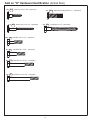
Key Number: The rst two digits represent the step
number. The third digit represents the order in which
the part is listed in the step.
Note that if the part is used in multiple steps then
the key number only reects the rst step it is used in.
Part Quantity Key Number
Order Listed
(The order the part is
listed in step 1)
Part Description Part Size
2X 012 Post 2 x 4 x 83”
00
Your Key To Quick Assembly
SAVE TIME - TIP #1:
Wood parts are found in Box 2, 3, 4 & 5. Open each box with wood parts and
look for the Key Number stamped on the end of the wood part (see chart below).
Sort each wood part into the different assembly steps.
SAVE TIME - TIP #2:
In addition to the key number stamp, you can also identify the wood parts by
using the Parts Identication pages in the manual or the Parts Identication
weather resistant poster.
HARDWARE:
The majority of each hardware part comes packed in a separate bag so
you do not need to sort the hardware. Each assembly step indicates which
hardware (bolt, screw, washer etc.) you will require to complete the step.
SORTING WOOD PARTS INTO
EACH ASSEMBLY STEP WILL
SAVE TIME!
Step Step Step
01 2
Step Number
(This is Step 1)

8
2pc.
-
2768
-
1-1/4 x 3 x 42" Panel Floor
3632768
8pc.
-
2609
- 1 x 5 x 40-5/8" - Floor Board
3632609
1pc.
-
2757
LT Post Assembly
1-1/4 x 2-1/2 x 87"
37632757
1pc.
-
2648
-
1 x 4 x 40-5/8 - Floor Board
3632648
5pc.
-
2769
-
1-1/4 x 3 x 42" Panel BT Frame
3632769
Part Identification (Next Generation E)
3pc.
-
2770
-
1-1/4 x 2-1/2 x 87" End Post Left
3632770
1pc.
-
2758
RT Post Assembly
1-1/4 x 2-1/2 x 87"
37632758
2pc.
-
2779
-
1 x 6 x 19" Access Board
3632779
1pc.
-
2608
-
1-1/4 x 3 x 40-3/4" - Floor Joist
3632608
2pc.
-
2776
-
1-1/4 x 2-1/2 x 51" Rock Rail
3632776
3pc.
-
2781
-
1 x 6 x 19" RK Board B
3632781
2pc.
-
2780
-
1 x 6 x 19" RK Board A
3632780
2pc.
-
2778
-
5/4 x 4 x 14¼"
SW Ground MOD
3632778
1pc.
-
2630
-
1-1/4 x 5-1/2 x 42" SW Top
39632630
2pc.
-
2777
-
2 x 2 x 40-1/4" Side Joist MOD
3632777
3pc.
-
2771
-
1-1/4 x 2-1/2 x 87" End Post
3632771
2pc.
-
2772
-
1-1/4 x 3 x 42" Panel Floor Support
3632772
2pc.
-
2774
-
1-1/4 x 3 x 42" Upright
3632774
1pc.
-
2614
-
4 x 6 x 88" Engineered Beam
3632614
1pc.
-
2615
- 4 x 4 x 50-15/16" SW Upright
3632615
2pc. - 2775 -
1-1/4 x 3 x 42" Panel Cross Support
3632775
2pc.
-
2613
-
2 x 3 x 86-11/16" Heavy SW Post
3632613
1pc.
-
2616
-
5/4 x 4 x 46-1/2" SW Support
3632616
2pc.
-
2607
-
1-1/4 x 3 x 22" Diagonal
3632607

9
2pc.
-
2751
-
MOD Roof Bottom 1-3/16 x 16-13/16 x 44"
37632751
2pc.
-
2761
-
Roof Sleeper C ¾ x 2 x 35" -
3632761
1pc.
-
2752
-
MOD Roof Front 1¼ x 20-7/16 x 44"
37632752
1pc.
-
2753
- MOD Roof Back 1-1/4 x 20-3/16 x 44"
37632753
2x
- Narrow Angle Bracket
Set (2 Pk)
(3200632)
10pc.
S0
- Truss Screw
#8 x 7/8"
(52933505)
2pc.
S4
- Wood Screw
#8 x 3" (52043530)
4pc.
LW1
- 1/4" Lock Washer
(51303200)
30pc.
S11
- Wood Screw
#8 x 2"
(52043520)
4pc.
H3
- Hex Bolt 1/4 x 2-1/2" - (53703222)
8pc.
S3
- Wood Screw
#8 x 2-1/2" (52043522)
4pc.
FW1
- 1/4" Flat Washer
(51103200)
35pc.
S20
- Wood Screw
#8 x 1-3/8"
- (52043516)
Add On "G" Part Identification (Quantities per box) (2 Boxes)
4pc.
-
2759
Roof End
1-1/4 x 3 x 10" -
3632759
4pc.
-
2760
-
Roof Support 1¼ x 2¼ x 37½" -
3632760
2pc.
-
9080
MOD Sunburst A
1 x 4 x 11-1/2"
3639080
4pc.
-
9081
MOD Sunburst B
1 x 4 x 7-1/4" -
3639081
2pc.
-
8305
Starburst Centre
5/4 x 6 x 12" -
3638305
2pc.
-
9082
MOD Sunburst Bottom
1 x 4 x 30" -
3639082
1pc.
-
8074
Dormer Burst
1 x 4 x 5-1/2" -
3638074
1pc.
-
8069
Dormer Cleat
2 x 4 x 10" -
3638069
2pc.
-
8072
Dormer Side Burst
1 x 3 x 6-3/4" -
3638072
1pc.
-
8071
Dormer Centre
1 x 3 x 10-3/4" -
3638071
2pc.
-
8070
Dormer Side
1 x 3 x 13-5/8" -
3638070
1pc.
-
8068
-
Dormer Roof Set
(Right/Left Dormer)
3638068
1pc.
-
8073
Dormer Bottom
1 x 2 x 22" -
3638073
1pc.
D4
- 2x2 Robertson Driver Bit
(9200014)
14pc.
S30
- Wood Screw
#8 x 1-1/16"
(52043517)
4pc.
TN1
- 1/4" T-Nut
(54503200)
(4) 9450
Roof Tie - 1-1/4 x 2 x 7-9/16"
(31.8 x 50.8 x 192mm) 3639450

10
2pc.
-
5536
- 5/8 x 2 x 6-3/4"
Counter Side -
38045536
2pc.
-
6136
- 1 x 2 x 12-9/16"
Counter Brace - 38046136
1pc.
-
2804
- 5/4 x 3 x 39" - Wall Top
- 3632804
1pc.
-
2686
- 5/8 x 2-3/4 x 40-5/8" - Counter Front
- 3632686
2pc.
-
2774
- 1-1/4 x 3 x 42 - Upright
- 3632774
3pc.
-
2771
- 1-1/4 x 2-1/2 x 87" - End Post
- 3632771
2pc.
-
2772
- 1-1/4 x 3 x 42" - Panel Floor Support
- 3632772
5pc.
-
2769
- 1-1/4 x 3 x 42" - Panel BT Frame
- 3632769
1pc.
-
2630
- 1-1/4 x 5-1/2 x 42" - SW Top
- 39632630
1pc.
-
2687
- 1 x 4 x 40-5/8" - Counter Back
- 3632687
1x
- Corner Bracket Set
(2 Pk) - (3206571)
1pc.
-
2757
- 1-1/4 x 2-1/2 x 87" - LT Post Assembly
- 37632757
3pc.
-
2770
- 1-1/4 x 2-1/2 x 87" - End Post Left
- 3632770
4x - 2649
1.27 x 18.8 x 41.91"
Lower Window Insert
(37632649)
1pc.
-
2758
- 1-1/4 x 2-1/2 x 87" - RT Post Assembly
- 37632758
2pc.
-
2776
- 1-1/4 x 2-1/2 x 51" - Rock Rail
- 3632776
1x - 2655 - 1.27 x 18.8 x 35.86"
Upper Window Insert
(37632655)
2pc.
-
2716
- 1 x 4 x 17-5/8" - Counter Mid Top
- 3632716
2pc.
-
2778
- 5/4 x 4 x 14-1/4"
SW Ground MOD
3632778
1x -
2665
- 1.4 x 20-1/4 x 38.8"
Half Wall Insert - (37632665)
2x -
2756
- 1-1/4 x 19-15/16 x 39-3/16"
Siding Assembly - (37632756)
2pc.
-
2607
-
1-1/4 x 3 x 22" - Diagonal
3632607
2pc.
-
2601
-
1-1/4 x 3 x 41-15/16"
-
Lower Jamb
- 3632601
3x
- Jamb Mount
(2 Pk)
(3206301)
1pc.
-
2658
-
2-13/32 x 6-3/4 x 34"
Folding Bench -
37632658
1pc.
-
2602
- 1-1/4 x 3 x 35-15/16" - Upper Jamb
- 3632602
Add on "H" Part Identification (Reduced Part Size)
Nominal Size Actual Size
5/4 x 5 15/16 x 4-1/4
5/4 x 6 15/16 x 5-1/4
2 x 2 1-1/2 x 1-1/2
1 x 4 5/8 x 3-3/8
1 x 6 5/8 x 5-3/8
1-1/4 x 2-1/4 1-1/4 x 2-1/4
1-1/4 x 3 1-1/4 x 3
4 x 4 3 x 3
4 x 6 3 x 5-1/4
- 1 x 2 x 8-1/4"
- 38045736
Counter Joist
4pc.
-
5736
1
x
U
t
e
n
s
ils
S
h
e
l
f
(
9
3
2
0
7
9
1
)
2pc.
-
2777
-
2 x 2 x 40-1/4" - Side Joist MOD
- 3632777
1pc.
-
9083
-
1-1/4 x 3 x 19-1/4" - Steering Wheel Block
- 3639083
2pc.
-
2768
- 1-1/4 x 3 x 42" - Panel Floor
- 3632768
2pc.
-
2775
- 1-1/4 x 3 x 42" - Panel Cross Support
- 3632775
1pc.
-
2685
- 1 x 4 x 40-5/8" - Counter Top
- 3632685
-
#
6
x
1
0
m
m
B
lu
n
t
(
5
2
4
0
2
9
0
2
)
1
0
x
(
9
3
2
0
8
8
9
)
-
P
o
t
P
a
n
S
p
a
t
u
la
1
x
1
x
(
3
3
2
0
7
8
4
)
-
S
t
o
v
e
P
o
in
t
P
a
n
S
c
r
e
w
1
x
-
F
a
u
c
e
t
(
9
3
2
0
8
8
1
)
1
x
-
S
in
k
K
n
o
b
(
R
e
d
)
(
9
3
2
0
3
8
2
)
1
x
-
S
in
k
K
n
o
b
(
B
lu
e
)
(
9
3
2
0
4
8
2
)
1
x
-
D
e
e
p
S
in
k
(
9
3
2
0
9
6
9
)
8
x
-
M
o
u
n
t
C
lip
s
(
9
3
2
0
0
8
8
)
1
x
-
D
e
l
u
x
e
K
i
t
c
h
e
n
S
e
t
(
3
3
20
9
6
9
)
1x
- Hand Grip
(9320240)
1x
- Steering Wheel
(3320255)
1
x
-
M
o
d
3
P
a
n
e
T
r
a
n
s
o
m
-
(
9
3
2
0
1
3
8
)
1pc.
-
2608
-
1-1/4 x 3 x 40-3/4" - Floor Joist
- 3632608
2x
- Rebar Ground Stake
(9290318)
1x
- Rocks (5pk)
(3320386)
2pc.
-
2779
-
1 x 6 x 19" - Access Board
3632779
2pc.
-
2780
-
1 x 6 x 19" - RK Board A
3632780
3pc.
-
2781
-
1 x 6 x 19" - RK Board B
3632781
-
8pc. 2609
- 1 x 5 x 40-5/8" - Floor Board
- 3632609
1pc.
-
2648
-
1 x 4 x 40-5/8 - Floor Board
- 3632648

11
(10) S13
- Pan Screw
#6 x 5/8" - (52413908)
(22) TS
- Trim Screw
#6 x 30mm - (52953911)
(70)
S30
- Wood Screw
#8 x 1-1/16" - (52043517)
(1)
D4
- 2 x 2 Robertson Driver Bit - (9200014)
(16)
S3
- Wood Screw
#8 x 2-1/2"
- (52043522)
(6)
S4
- Wood Screw
#8 x 3" - (52043530)
(90)
S20
- Wood Screw
#8 x 1-3/8" - (52043516)
(4)
S7
- Pan Screw
#12 x 2" - (52433620)
(10) S11
- Wood Screw
#8 x 2" - (52043520)
(5)
S10
- Pan Screw
#8 x 1" - (52433510)
Add on "H" Hardware Identification (Actual Size)
(6) FW2
- 5/16" Flat Washer - (51103300)
(5) BN1
- 1/4" Barrel Nut
- (54803200)
(36) TN1
- 1/4" T - Nut
-
(54503200)
(41) LW1
- 1/4" Lock Washer - (51303200)
(5)
PB2
- Pan Bolt
1/4 x 1-1/4"
- (53433212)
(44)
FW1
- 1/4" Flat Washer - (51103200)
(5)
FW0
- 3/16" Flat Washer - (51103100)
(2)
TN2
- 5/16" T- Nut
- (54503300)
(2)
LW2
- 5/16" Lock Washer - (51303300)
(100)
S0
- Truss Screw
#8 x 7/8"
(52933505)

12
2pc. WB1
-
Wafer Bolt w/ Nylok 5/16 x 1"
- (53613310)
2pc.
WL3
- Wafer Lag
1/4 x 1-3/8" - (52613216)
2pc.
LS3
- Lag
Screw 1/4 x 3"
- (52213230)
4pc.
H1
-
Hex Bolt 1/4 x 1-1/2"
- (53703212)
24pc.
H9
-
Hex Bolt 1/4 x 1-1/4"
- (53703211)
4pc.
H11
-
Hex Bolt 1/4 x 2-3/4"
- (53703223)
4pc. H10
-
Hex Bolt 1/4 x 2-1/4"
- (53703221)
(17)
WL5
- Wafer Lag
1/4 x 2-1/2"
- (52613222)
Add on "H" Hardware Identification (Actual Size)

13
1pc.
-
2804
- 5/4 x 3 x 39" Wall Top
3632804
1pc.
-
2709
1-1/4 x 15-3/4 x 40-3/4"
Door Window Panel
37602709B
(3200170)
1x
- Welded Chain Bag
25" x 2
1pc.
- Door Hardware
3201710
3pc.
-
649A
1.27 x 18.8 x 20-15/16"
Short Half Wall
37632649A
1pc.
-
2665
- 1.4 x 20-1/4 x 38.8"
Half Wall Insert
37632665
1pc. - Gable Clock Assembly
(3320164)
1pc. - Corner Bracket
Set (2 Pk)
(3206571)
3x
- Jamb Mount (2 Pk)
(3206301)
1x
- Beam Brkt. Set
(3200143) (2pk)
1x
- Rocks (5pk)
(3320386)
1x
- Swing Hanger (6 Pk)
(3206106)
1x
- Rebar Ground
Stake (6 Pk)
(3200318)
1x
- L Beam Brkt.
(3200145) (2pk)
Add on "J" Part Identification
54" x 4
2pc.
-
2756
- 1-1/4 x 19-15/16 x 39-3/16"
Siding Assembly
37632756
1pc.
-
2602
- 1-1/4 x 3 x 35-15/16"
Upper Jamb
3632602
2pc.
-
2601
- 1-1/4 x 3 x 41-15/16"
Lower Jamb
3632601
1x
- Hand Grip
Yellow (9320240)
1pc.
-
2611
-
5/4 x 5 x 39-5/8"
Table Top
3632611
1pc.
-
2612
-
2 x 2 x 39-5/8"
Table Support
3632612
1pc.
-
2717
-
3/4 x 1-3/4 x 9-3/4"
Clock Block
3632717
1pc.
MOD 3 Pane Transom
(2Pk) 3320138
2pc.
-
2655
1.27 x 18.8 x 35.86"
Upper Window Insert
37632655
2x
- Swing Belt Seat
(9320130)
1x - Steel Acro Bar
(9200131)
2x
- Acro Handle
(9200133)
1x
- Quick Link
(Threaded)(6pk)
(3206020)
3pc. -
MOD Arch
(9333603)
1pc. -
Flower Box
(9320401)
1pc. -
Cedar Summit Plaque
(9320358)
1pc.
-
2715
-
5/4 x 3 x 10"
Door Stop
3632715
(1)
KidKraft
ID Plaque
(9320370)
- Door Bumper
(9331632)
1x
ZL 102 Aluminum Alloy
Acro Handle
FR
n/a
0
DRAWING
5
4
3
2
1
DO NOT SCALE
Mount Forest, Ontario N0G 2L1
375 Sligo Road West, Box 10
Scale
Rev.
whole without permission of Solowave is prohibited.
Inc. Any transmission or reproduction in part or as a
A
Part #
Part Name
Material
Process
Weight
Finish/Color
SIZE
1 of 4
Drn.
Chkd.
Date
A
B
C
D
Sheet
REV
contained herein is the sole property of S olowave Design
This drawing is proprietary and confidential. All information
(Refer to Solowave Design General Material Specs)
3 RD ANGLE ORTHOGRAPHIC
PROJECTION
Dimensions in inches [mm]. Drawing for reference. Please refer to 3D CAD model for actual geometry
11/10/2015
APP
Apvd.
DRN
DATE
0.1
DESCRIPTION
GEN. TOLERANCES:
FRACTIONAL
1/64"
ANGULAR: MACH BEND
MM 0.4
ONE PLACE DECIMAL
Green PMS 343C Plastisol Coating
High Pressure Die Cast
0.29 Kg
16.5
.65
.65
R.65
16.5
16.5
.50
12.7
189.2
7.45
.50
12.7
146.1
31.8
R1.25
5.75
25.4
1.00R
6.75
171.5
1x KidKraft ID Plaque
(9320374)
1x KidKraft Logo
Plaque (3320353)

14
10pc. S3
- Wood Screw
#8 x 2-1/2" - (52043522)
4pc.
S4
- Wood Screw
#8 x 3"
- (52043530)
18pc.
S7
- Pan Screw
#12 x 2" - (52433620)
8pc.
S10
- Pan Screw
#8 x 1"
(52433510)
Add on "J" Hardware (Actual Size)
38pc. LW1
- 1/4" Lock Washer -
(51303200)
32pc.
TN1
- 1/4" T - Nut
(54503200)
5pc. BN1
- 1/4" Barrel Nut
(54803200)
10pc.
TN2
- 5/16" T- Nut
(54503300)
23pc.
LN2
5/16" Lock Nut
(54303300)
5pc.
LW2
- 5/16" Lock Washer -
(51303300)
101pc.
S0
- Truss Screw
#8 x 7/8"
- (52933505)
32pc.
S13
- Pan Screw
#6 x 5/8"
- (52413908)
60pc.
FW2
- 5/16" Flat Washer -
(51103300)
40pc.
FW1
- 1/4" Flat Washer -
(51103200)
5pc.
FW0
- 3/16" Flat Washer -
(51103100)
1pc.
D4
2 x 2 Robertson Driver Bit
(9200014)
1pc.
S5
- Pan Screw
#8 x 1/2"
(52433502)
65pc.
S30
- Wood Screw
#8 x 1-1/16" - (52043517)
78pc.
S20
- Wood Screw
#8 x 1-3/8" - (52043516)
8pc.
S18
- Wood Screw
#6 x 1" - (52013910)
28pc.
S11
- Wood Screw
#8 x 2" - (52043520)

15
4pc. G8
- Hex Bolt 5
/16 x 2" (53703320)
7pc. G21
- Hex Bolt 5
/16 x 3-3/4" (53703333)
3pc.
G4
- Hex Bolt 5
/16 x 4" (53703340)
14pc.
G7
- Hex Bolt 5
/16 x 5-1/2"
(53703352)
Add on "J" Hardware (Actual Size)
2pc. LS3
- Lag Screw
1/4 x 3" - (52213230)
2pc. WL3
- Wafer Lag
1/4 x 1-3/8"
(52613216)
16pc. WL5
- Wafer Lag
1/4 x 2-1/2"
(52613222)
2pc.
WB1
- Wafer Bolt w/ Nylok
5/16 x 1"
(53613310)
5pc.
PB2
- Pan Bolt
1/4 x 1-1/4"
(53433212)
3pc.
WB7
- Wafer Bolt w/ Nylok
5/16 x 3" (53613330)
4pc.
H11
- Hex Bolt
1/4 x 2-3/4"
(53703223)
4pc.
H10
- Hex Bolt
1/4 x 2-1/4"
(53703221)
24pc.
H9
- Hex Bolt
1/4 x 1-1/4" (53703211)

16
2pc.
-
9084
Lower Tunnel Insert
1.27 x 8 x 18.8" - 37639084
2pc.
-
9089
Upper Tunnel Insert
1.27 x 8-1/4 x 18-51/64" - 37639089
2pc.
-
9088
Tunnel Side Joist 1-1/4 x 3 x 36" - 3639088
2pc.
-
9086
Tunnel Top 1-1/4 x 3 x 14-7/16" - 3639086
7pc.
-
9092
Floor Board 1 x 5 x 16-7/8" - 3639092
1pc.
-
9087
Floor Board 1 x 4 x 16-7/8" - 3639087
1
pc
.
- M
O
D
T
u
n
n
e
l
Pa
n
e
l
S
e
t
(
4
P
k
) (
3
3
3
0
1
0
1
)
1pc.
-
9086
Swing Bracket Set (4 Pk)
( 3201532)
4pc.
FW2
- 5/16" Flat Washer
(51103300)
4pc.
WL3
- 1/4 x 1-3/8" Wafer Lag
(52613216)
10pc.
MB1
- #12 x 1/2" Pan Bolt
(53433602)
4pc.
WB2
- 5/16 x 1-3/8" Wafer Head Bolt w/ Nylok -(53613316)
10pc.
LN4
- #12 Lock Nut - (54303600)
4pc.
TN2
- 5/16" T-Nut - (54503300)
2pc.
- 48" High Rail Slide
(7310248)
36pc.
S10
- #8 x 1 Pan Screw
(52433510)
16pc.
S4
- Wood Screw
#8 x 3" (52043530)
32pc.
S20
- Wood Screw
#8 x 1-3/8"
- (52043516)
Part Identification (Add On "T")
24pc. S0
- Truss Screw
#8 x 7/8"
(52933505)
4pc.
FW1
- 1/4" Flat Washer
(51103200)

17
1pc. TN1
- 1/4" T - Nut
(54503200)
4pc.
FW1
- 1/4" Flat Washer - (51103200)
19pc. S6
- Pan Screw
#12 x 1"
- (52433610)
Part Identification (Actual Part Size)
Part Identification (Reduced Part Size)
1pc. S4
- Wood Screw
#8 x 3"
- (52043530)
1pc.
LW1
- 1/4" Lock Washer - (51303200)
1/4 x 4¼" - (53703241)
H8
1pc.
- Hex Bolt
1x D1
- Quadrex
Driver Bit (9200015)
18pc.
S0
- Truss Screw
#8 x 7/8"
- (52933505)
37638935
8935
(1) Lower SL Insert 1.36 x 8-1/8 x 26¼"
(1) TNR Upright 1¼ x 3 x 20¼"
8965
3638965
3638934
8934
(1) SL Gusset 1¼ x 3 x 15¾"
3638963
8963
(1) TNR Ground Brace 1¼ x 3 x 32¼"
5pc. S7
- Pan Screw
#12 x 2"
- (52433620)
94pc.
PB1
- Pan Bolt
1/4 x 3/4"
- (53453203)
3pc. S11
- Wood Screw
#8 x 2"
- (52043520)
1pc.
PB2
- Pan Bolt
1/4 x 1-1/4"
- (53433212)
8pc.
FW6
- #12 Screw Bezel - (9299500)
94pc.
LN1
-
1/4 Lock Nut - (54303200)
1pc. PB6
- Pan Bolt
1/4 x 1"
- (53413210)
WL5
(1) Wafer Lag Screw 1/4 x 2-1/2"
(52613222)

18
1x
- MOD Side Lite
(9320516)
1x
- TNR 3 Tube Support
(9203601)
1x
- TNR 3 Post
Mount
(9203602)
1x
- TNR3 Short Exit
(3310232)
1x
- TNR3 Extend Flange Rt
(3310231)
1x
- TNR3 Extend Flange Lt
(3310230)
1x
- TNR 2 Slide Exit Top
(3310224)
1x
- TNR 2 Slide Clamp Ring
(10Pk)
(9300220)
9x
- TNR 2 Slide Elbow
(3310221)
(1) Rebar Ground Stake
(9290318)
Part Identification (Reduced Part Size)
10x - TNR 2 Clamp Ring
(9300220) (Yellow)
10pcs number 3300220

19
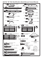
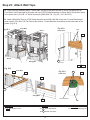
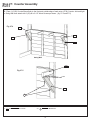
B. If there are any missing or damaged pieces or you need assistance with
assembly please contact the consumer relations department directly. Call us
before going back to the store.
STOP STOPSTOP STOP
Key Number: The rst two digits represent the step
number. The third digit represents the piece. Note
that if the part is used in multiple steps then the
number only reects the rst step it is used in.
Quantity Key Number Part Description,
Part Size
2X 012 Post 2 x 4 x 83”
C. Read the assembly manual completely, paying special attention to ANSI warnings;
notes; and safety/maintenance information on pages 1 - 6.
D. Before you discard your cartons ll out the form below.
• The carton I.D. stamp is located on the end of each carton. The tracking number is
located on the KidKraft ID Plaque (9320374).
• Please retain this information for future reference. You will need this information if you
contact the Consumer Relations Department.
• Please refer to Page 6 for proper hardware assembly.
• Each step indicates which bolts and/or screws you will need for assembly, as well as
any at washers, lock washers, t-nuts or lock nuts.
A.
This is the time for you to inventory all your hardware, wood and accessories,
referencing the parts identication sheets. This will assist you with your assembly.
• The wood pieces will have the key number stamped on the ends of the boards.
Organize the wood pieces by step, as per the key numbering system below.
+31 20 305 8620
For online parts replacement visit
https://parts.kidkraft.eu/
1.800.933.0771 or 972.385.0100
For online parts replacement visit
https://parts.kidkraft.com/
First Step: Inventory Parts - Read This Before Starting Assembly
CARTON I.D. STAMP: __ __ __ __ __ 14459 ___ (Box 4)
CARTON I.D. STAMP: __ __ __ __ __ 14459 ___ (Box 5)
CARTON I.D. STAMP: __ __ __ __ __ 14459 ___ (Box 6)
CARTON I.D. STAMP: __ __ __ __ __ 14459 ___ (Box 1)
CARTON I.D. STAMP: __ __ __ __ __ 14459 ___ (Box 2)
CARTON I.D. STAMP: __ __ __ __ __ 14459 ___ (Box 3)
MODEL NUMBER: F25010
TRACKING NUMBER (from ID Plaque):

20
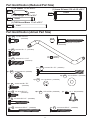
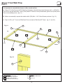
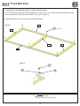
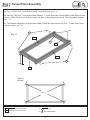
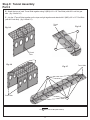
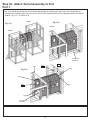
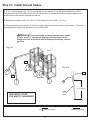
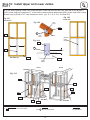
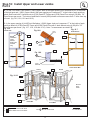
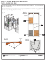
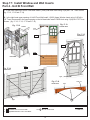
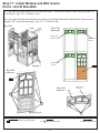
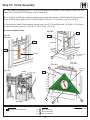
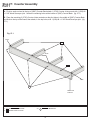
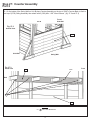
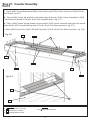
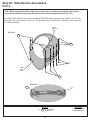
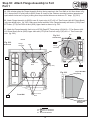
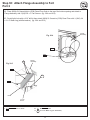
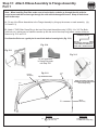
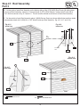
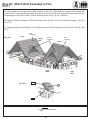
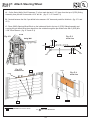
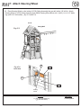
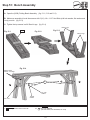
It is important to assemble the frame on a at, smooth surface.
A: Place (2771) End Post and (2770) End Post Left side by side with the grooves facing up and in. Put (2770)
End Post Left on the right hand side. Place (2775) Panel Cross Support in the top grooves, (2772) Panel Floor
Support in the middle grooves and (2769) Panel BT Frame in the bottom grooves. (g. 1.1)
B: Make sure assembly is square then attach with 4 (S30) #8 x 1-1/16” Wood Screws per board. (g. 1.1)
C: Tap 3 (TN1) 1/4” T-nuts in (2775) Panel Cross Support and (2772) Panel Floor Support and 2 in (2769) Panel
BT Frame. (g. 1.1 and 1.2)
48 x #8 x 1-1/16” Wood Screw
32 x 1/4” T-nut
4 x End Post 1-1/4 x 2-1/2 x 87”
4 x End Post Left 1-1/4 x 2-1/2 x 87”
4 x Panel Cross Support 1-1/4 x 3 x 42”
4 x Panel Floor Support 1-1/4 x 3 x 42”
4 x Panel BT Frame 1-1/4 x 3 x 42”
S30
2775
Wood Parts
Hardware
2772
2771
2770
2769
Fig. 1.2
Fig. 1.1
Bottom
Top
2772
2775
2770
2771
2769
S30
S30
x 3
x 3
x 2
x 4
x 4 per
board
Flush
Flush
Step 1: Side Wall Prep
Part 1
TN1
TN1
TN1
TN1
TN1
Page is loading ...
Page is loading ...
Page is loading ...
Page is loading ...
Page is loading ...
Page is loading ...
Page is loading ...
Page is loading ...
Page is loading ...
Page is loading ...
Page is loading ...
Page is loading ...
Page is loading ...
Page is loading ...
Page is loading ...
Page is loading ...
Page is loading ...
Page is loading ...
Page is loading ...
Page is loading ...
Page is loading ...
Page is loading ...
Page is loading ...
Page is loading ...
Page is loading ...
Page is loading ...
Page is loading ...
Page is loading ...
Page is loading ...
Page is loading ...
Page is loading ...
Page is loading ...
Page is loading ...
Page is loading ...
Page is loading ...
Page is loading ...
Page is loading ...
Page is loading ...
Page is loading ...
Page is loading ...
Page is loading ...
Page is loading ...
Page is loading ...
Page is loading ...
Page is loading ...
Page is loading ...
Page is loading ...
Page is loading ...
Page is loading ...
Page is loading ...
Page is loading ...
Page is loading ...
Page is loading ...
Page is loading ...
Page is loading ...
Page is loading ...
Page is loading ...
Page is loading ...
Page is loading ...
Page is loading ...
Page is loading ...
Page is loading ...
Page is loading ...
Page is loading ...
Page is loading ...
Page is loading ...
Page is loading ...
Page is loading ...
Page is loading ...
Page is loading ...
Page is loading ...
Page is loading ...
Page is loading ...
Page is loading ...
Page is loading ...
Page is loading ...
Page is loading ...
Page is loading ...
Page is loading ...
Page is loading ...
Page is loading ...
Page is loading ...
Page is loading ...
Page is loading ...
Page is loading ...
Page is loading ...
Page is loading ...
Page is loading ...
Page is loading ...
Page is loading ...
Page is loading ...
Page is loading ...
Page is loading ...
Page is loading ...
Page is loading ...
Page is loading ...
Page is loading ...
Page is loading ...
Page is loading ...
Page is loading ...
-
 1
1
-
 2
2
-
 3
3
-
 4
4
-
 5
5
-
 6
6
-
 7
7
-
 8
8
-
 9
9
-
 10
10
-
 11
11
-
 12
12
-
 13
13
-
 14
14
-
 15
15
-
 16
16
-
 17
17
-
 18
18
-
 19
19
-
 20
20
-
 21
21
-
 22
22
-
 23
23
-
 24
24
-
 25
25
-
 26
26
-
 27
27
-
 28
28
-
 29
29
-
 30
30
-
 31
31
-
 32
32
-
 33
33
-
 34
34
-
 35
35
-
 36
36
-
 37
37
-
 38
38
-
 39
39
-
 40
40
-
 41
41
-
 42
42
-
 43
43
-
 44
44
-
 45
45
-
 46
46
-
 47
47
-
 48
48
-
 49
49
-
 50
50
-
 51
51
-
 52
52
-
 53
53
-
 54
54
-
 55
55
-
 56
56
-
 57
57
-
 58
58
-
 59
59
-
 60
60
-
 61
61
-
 62
62
-
 63
63
-
 64
64
-
 65
65
-
 66
66
-
 67
67
-
 68
68
-
 69
69
-
 70
70
-
 71
71
-
 72
72
-
 73
73
-
 74
74
-
 75
75
-
 76
76
-
 77
77
-
 78
78
-
 79
79
-
 80
80
-
 81
81
-
 82
82
-
 83
83
-
 84
84
-
 85
85
-
 86
86
-
 87
87
-
 88
88
-
 89
89
-
 90
90
-
 91
91
-
 92
92
-
 93
93
-
 94
94
-
 95
95
-
 96
96
-
 97
97
-
 98
98
-
 99
99
-
 100
100
-
 101
101
-
 102
102
-
 103
103
-
 104
104
-
 105
105
-
 106
106
-
 107
107
-
 108
108
-
 109
109
-
 110
110
-
 111
111
-
 112
112
-
 113
113
-
 114
114
-
 115
115
-
 116
116
-
 117
117
-
 118
118
-
 119
119
-
 120
120


KidKraft Kingsbridge Wooden Swing Set / Playset Assembly Instruction
- Type
- Assembly Instruction
Ask a question and I''ll find the answer in the document
Finding information in a document is now easier with AI
Related papers
-
KidKraft Abbeydale Clubhouse Wooden Playset Assembly Instruction
-
-
KidKraft Forest Hill Retreat Wooden Swing Set / Playset Assembly Instruction
-
-
-
-
-
-
-
Other documents
-
 Baxton Studio 28862-5308-HD Operating instructions
-
 Lyfco W20164 Operating instructions
-
ROOMS TO GO 23181908 Assembly Instructions
-
-
-
Home Decorators Collection 0795600960 Installation guide
-
 Usl SK19089ABR1-GY Installation guide
-
 Usl SK18795A-BB Operating instructions
-
Hooker 5474-75500 Assembly Instructions
-


