Page is loading ...

©20ĂĀƫCyber Power Systems, Inc. All rights reserve. K01-0000754-0Ă
SAVE THESE INSTRUCTIONS
Please read this manual and follow the instructions for installation and operation.
INSTALLATION AND OPERATION MANUAL
SMART APP ONLINE
UPS SYSTEM
OL6KRT | OL8KRT | OL10KRT

II
©20ĂĀ Cyber Power Systems (USA), Inc. All rights reserved. All other trademarks are the property of their respective owners.
SAFETY INSTRUCTIONS
SAVE THESE INSTRUCTIONS
This manual contains important instructions that should be followed during installation and maintenance of
the UPS and batteries.
The Smart App Online 6-10kVA UPS models that are covered in this manual are intended for installation in
an environment within 32°F to 104°F (0°C to 40°C), free of conductive contaminants.
SPECIAL SYMBOLS
Warning: High voltage – Risk of Electric Shock
Caution - Important Instructions: must always be followed.
Do Not Discard: the UPS or UPS batteries in trash. The batteries
contain lead acid. For more information, contact your local recycling
or hazardous waste facility.
Information, advice, help
See applicable user manual

III
įĂĀĂĀƫ5!.ƫ+3!.ƫ5/0!)/ƫĨĩČƫ*ċƫ((ƫ.%#$0/ƫ.!/!.2! ċƫ((ƫ+0$!.ƫ0. !).'/ƫ.!ƫ0$!ƫ,.+,!.05ƫ+"ƫ0$!%.ƫ.!/,!0%2!ƫ+3*!./ċƫ
SAFETY INSTRUCTIONS CONT.
PERSONAL SAFETY
CAUTION
To reduce the risk of fire, connect the UPS to a branch circuit with 40 amperes
(6,000 VA)/50 amperes (8,000 VA)/70 amperes (10,000 VA) maximum over-current
protection in accordance with the National Electric Code, ANSI/NFPA 70.
The AC electrical service where the UPS is connected should be close to the unit and
easily accessible.
Please use only UL-marked mains cable, (e.g. the mains cable of your equipment), to
connect the UPS to the AC outlet.
Please use only UL-marked power cables to connect any equipment to the UPS.
When installing the equipment, ensure that the sum of the leakage current of the UPS
and the connected equipment does not exceed 3.5mA.
Do not unplug the unit from AC power during operation, as this will disconnect the
protective ground insulation.
Do not use an improper size power cord as it may cause damage to your equipment
and cause fire hazards.
Make sure everything is turned o and disconnected completely before conducting
any maintenance, repairs or shipment.
DO NOT INSTALL THE UPS WHERE IT WOULD BE EXPOSED TO DIRECT SUNLIGHT
OR NEAR A STRONG HEAT SOURCE!
DO NOT BLOCK OFF VENTILATION OPENINGS AROUND THE HOUSING!
DO NOT CONNECT DOMESTIC APPLIANCES SUCH AS HAIR DRYERS TO UPS
OUTPUT SOCKETS!
SERVICING OF BATTERIES SHOULD BE PERFORMED OR SUPERVISED BY
PERSONNEL KNOWLEDGE OF BATTERIES AND THE REQUIRED PRECAUTIONS.
KEEP UNAUTHORIZED PERSONNEL AWAY FROM BATTERIES!
FOR PERMANENTLY CONNECTED EQUIPMENT, A READILY ACCESSIBLE
DISCONNECT DEVICE SHALL BE INCORPORATED IN THE BUILDING
INSTALLATION WIRING.
RISK OF ELECTRIC SHOCK
A battery can present a risk of electric shock and high short circuit current. The
following precaution should be observed when working on batteries:
Remove watches, rings or other metal objects. Use tools with insulated handles.
The UPS must be connected to a grounded AC power outlet with fuse or circuit
breaker protection. DO NOT plug the UPS into an outlet that is not grounded. If you
need to power-drain this equipment, turn o and unplug the unit.

IV
įĂĀĂĀƫ5!.ƫ+3!.ƫ5/0!)/ƫĨĩČƫ*ċƫ((ƫ.%#$0/ƫ.!/!.2! ċƫ((ƫ+0$!.ƫ0. !).'/ƫ.!ƫ0$!ƫ,.+,!.05ƫ+"ƫ0$!%.ƫ.!/,!0%2!ƫ+3*!./ċƫ
RISK OF ELECTRIC SHOCK CONT.
(No User Serviceable Parts): Risk of electric shock, do not remove cover. No user
serviceable parts inside. Refer servicing to qualified service personnel.
To prevent the risk of fire or electric shock, install in a temperature and humidity
controlled indoor area, free of conductive contaminants. (Please see specifications for
acceptable temperature and humidity range).
To avoid electric shock, turn o and unplug the unit before installing the input/output
power cord with a ground wire. Connect the ground wire prior to connecting the line
wires!
Connect the Protection Earth (PE) safety conductor before any other cables are
connected. (Fuses): To reduce the risk of fire, replace only with the same type and
rating of fuse.
SAFETY INSTRUCTIONS CONT.
PERSONAL SAFETY CONT.
RISK OF ELECTRIC SHOCK
The battery can power hazardous components inside the unit, even when the AC input
power is disconnected.
The UPS should be placed near the connected equipment and easily accessible.
(Non-Isolated Battery Supply): Risk of electric shock, battery circuit is not isolated
from AC power source; hazardous voltage may exist between battery terminals and
ground. Test before touching.
All UPS models covered in this document are permanently-connected equipment and
only qualified maintenance personnel may carry out installations.
Wiring must be done by qualified personnel.
DO NOT USE FOR MEDICAL OR LIFE SUPPORT EQUIPMENT! Under no circumstances
should this unit be used for medical applications involving life support equipment
and/ or patient care.
DO NOT USE WITH OR NEAR AQUARIUMS! To reduce the risk of fire, do not use with
or near aquariums. Condensation from the aquarium can come in contact with metal
electrical contacts and cause equipment to short out.
The unit has a dangerous amount of voltage. When the UPS indicators is on, the units
may continue to supply power thus the unit’s outlets may have a dangerous amount of
voltage even when it’s not plugged in to the wall outlet.
PRODUCT SAFETY

V
įĂĀĂĀƫ5!.ƫ+3!.ƫ5/0!)/ƫĨĩČƫ*ċƫ((ƫ.%#$0/ƫ.!/!.2! ċƫ((ƫ+0$!.ƫ0. !).'/ƫ.!ƫ0$!ƫ,.+,!.05ƫ+"ƫ0$!%.ƫ.!/,!0%2!ƫ+3*!./ċƫ
BATTERY
Do not dispose of batteries in fire as the battery may explode.
Do not open or mutilate the battery, released electrolyte is harmful to the
skin and eyes.
SAFETY INSTRUCTIONS CONT.
PRODUCT SAFETY CONT.

VI
įĂĀĂĀƫ5!.ƫ+3!.ƫ5/0!)/ƫĨĩČƫ*ċƫ((ƫ.%#$0/ƫ.!/!.2! ċƫ((ƫ+0$!.ƫ0. !).'/ƫ.!ƫ0$!ƫ,.+,!.05ƫ+"ƫ0$!%.ƫ.!/,!0%2!ƫ+3*!./ċƫ
TABLE OF CONTENTS
SAFETY INSTRUCTIONS.................................................................................................................................II
Special Symbols............................................................................................................................................................................II
Personal Safety............................................................................................................................................................................III
Product Safety ............................................................................................................................................................................IV
INTRODUCTION..............................................................................................................................................1
Smart App Online UPS Systems................................................................................................................................................1
UPS Extended Battery Modules................................................................................................................................................1
Step-Down Transformer..............................................................................................................................................................1
Unpacking Procedures...............................................................................................................................................................2
Whats In The Box.........................................................................................................................................................................3
OVERVIEW..........................................................................................................................................4
Power Module...............................................................................................................................................................................4
INSTALLING YOUR UPS SYSTEM....................................................................................................................6
System Block Diagram...............................................................................................................................................................6
Hardware Installation Guide......................................................................................................................................................6
HARDWARE INSTALLATION ..........................................................................................................................8
Rackmount Installation ..............................................................................................................................................................8
Vertical/Tower Installation........................................................................................................................................................10
ELECTRICAL INSTALLATION........................................................................................................................11
Input/Output Configuration....................................................................................................................................................11
Backfeed Protection Operation..............................................................................................................................................12
Without Backfeed Protection Configuration......................................................................................................................13
With Backfeed Protection Configuration.............................................................................................................................14
EXTENDED BATTERY MODULE INSTALLATION...........................................................................................14
Rear Panel Description..............................................................................................................................................................14
Connection With Power Module...........................................................................................................................................14
OPTIONAL LCD CONTROL PANEL INSTALLATION......................................................................................17
Remote Control...........................................................................................................................................................................17
Wall-mounting Instructions......................................................................................................................................................17
UPS SYSTEM STARTUP..................................................................................................................................18
USING THE UPS SYSTEM..............................................................................................................................19
LCD Module................................................................................................................................................................................19
LCD M e n u Tre e ............................................................................................................................................................................20
MAINTENANCE.............................................................................................................................................29
Battery Replacement ................................................................................................................................................................30
TECHNICAL SPECIFICATIONS......................................................................................................................31
TROUBLESHOOTING...........................................................................................................................................34
PRODUCT REGISTRATION...........................................................................................................................35
LIMITED WARRANTY AND CONNECTED EQUIPMENT GUARANTEE..........................................................36
CONFORMANCE APPROVAL........................................................................................................................40

įĂĀĂĀƫ5!.ƫ+3!.ƫ5/0!)/ƫĨĩČƫ*ċƫ((ƫ.%#$0/ƫ.!/!.2! ċƫ((ƫ+0$!.ƫ0. !).'/ƫ.!ƫ0$!ƫ,.+,!.05ƫ+"ƫ0$!%.ƫ.!/,!0%2!ƫ+3*!./ċƫ
1
INTRODUCTION
CyberPower Smart App Online rack/tower UPS systems, with double-conversion topology, provide sine
wave output to mission-critical applications and equipment requiring seamless power correction. These
units oer generator compatibility and deliver clean AC power with zero transfer time.
They oer Smart Battery Management (SBM), which helps extend overall battery life, and Fast Charge
Technology, which helps keep charge times to less than five hours, regardless of the number of Extended
Battery Modules (EBMs). Features include a rotatable LCD control panel, energy-saving GreenPower UPS™
ECO Mode technology, and PowerPanel® Business Edition software for monitoring and managing the UPS.
Smart App Online 6-10kVA UPS systems come with a three-year warranty and a $300,000 Connected
Equipment Guarantee.
UPS EXTENDED BATTERY MODULES
Extended Battery Modules (EBMs) from CyberPower increase battery runtimes during power outages. Each
rack/tower convertible EBM uses 3U of rack space, depending upon the model, and can be installed in a
tower form factor to match the UPS installation. The DC plug-and-play power connectors allow to daisy-
chain additional EBMs to a UPS system. EBMs compatible with Smart App Online UPS systems also have
a built-in battery charger, providing Fast Charge Technology to quickly restore the backup power supply.
Every CyberPower EBM has a three-year warranty.
STEP-DOWN TRANSFORMER
CyberPower Step-Down and Isolation Transformers (OL6KSTF/OL10KSTF) are designed for a variety of
CyberPower UPS systems. When combined with the UPS systems, the Step-down transformer converts
voltage from 200-240V down to 100-120V.

įĂĀĂĀƫ5!.ƫ+3!.ƫ5/0!)/ƫĨĩČƫ*ċƫ((ƫ.%#$0/ƫ.!/!.2! ċƫ((ƫ+0$!.ƫ0. !).'/ƫ.!ƫ0$!ƫ,.+,!.05ƫ+"ƫ0$!%.ƫ.!/,!0%2!ƫ+3*!./ċƫ
2
1 2 3
4 5 6
INTRODUCTION CONT.
UNPACKING PROCEDURES
The UPS system is very heavy, please handle with care. Wear safety shoes and use a hydraulic equipment
lift if one is available. At least two people are required for all handling operations, including unpacking,
lifting, and installation in a rack system. Do not use the lifting straps to carry the unit around; they are
provided to manually unpack the unit only.
USE LIFTING STRAPS TO REMOVE UNIT FROM THE BOX.
Information, advice, help

įĂĀĂĀƫ5!.ƫ+3!.ƫ5/0!)/ƫĨĩČƫ*ċƫ((ƫ.%#$0/ƫ.!/!.2! ċƫ((ƫ+0$!.ƫ0. !).'/ƫ.!ƫ0$!ƫ,.+,!.05ƫ+"ƫ0$!%.ƫ.!/,!0%2!ƫ+3*!./ċƫ
3
INTRODUCTION CONT.
WHATS IN THE BOX
ITEM CONTENT
QTY
1 Power Module 1
2 Extended Battery Module (EBM) 1
3 Left & Right Rackmount Rails 2
4 Left & Right Hanging Brackets 2
5 Phone Cable 1
6 USB Communication Cable 1
7
Input/Output Terminal Block Cover
(Included with OL8KRT and OL10KRT models)
1
8 Serial Interface Cable (RS-232) 1
9 NEMA L6-30P to IEC-320-C13 Power Cord 1
10 Quick Start Guide 1
11 Installation and Operation Manual 1
ITEM CONTENT QTY
12 Registration Warranty card 1
13
PowerPanel Management Software Download
Card
1
14 Rackmount Ears 4
15 Tie Plate 1
16 Black M5X7L Flat Head Screws 16
17 Black M5X12L Pan Head Screws 24
18 Silver M5X6L Pan Head Screws 12
19 Plastic Washers 16
20 Screw Hole Dust Covers 28
21 Rubber Pads 24
12
13 14
16 17 18 19 20 21
15
1
4
2
3
75 6 9 10 118

įĂĀĂĀƫ5!.ƫ+3!.ƫ5/0!)/ƫĨĩČƫ*ċƫ((ƫ.%#$0/ƫ.!/!.2! ċƫ((ƫ+0$!.ƫ0. !).'/ƫ.!ƫ0$!ƫ,.+,!.05ƫ+"ƫ0$!%.ƫ.!/,!0%2!ƫ+3*!./ċƫ
4
,1387%5($.(5
$9a
$&,1387
287387%5($.(5
$9a
121&5,7,&$/
/2$'
&5,7,&$/
/2$'
287387%5($.(5
$9a
287387%5($.(5
$9a
121&5,7,&$/
/2$'
&5,7,&$//2$'
,1387%5($.(5
$9a
OVERVIEW
POWER MODULE
1. Power Button/Power on Indicator
Master ON/OFF switch for the UPS. Indicates that the UPS is on and supplying power.
2. UPS Status/Fault/Replace Battery LED Indicator
Indicates the status of the UPS, displaying whether it is operating in On-Line, Battery or Bypass Mode,
if it has an internal fault or if the battery needs to be replaced.
3. Multifunction LCD Readout
Shows UPS status, information, settings and events.
4. Function Buttons
Scroll up, scroll down, Enter, and Escape.
5. Input Circuit Breaker
Provides input current overload and fault protection.
6. Power Cord (OL6KPM) OR Input/Output Terminal Block (OL8KPM/OL10KPM)
Connect to utility power/equipment load.
7. Output Circuit Breaker
Provides output current overload and fault protection.
FRONT: OL6KPM/OL8KPM/OL10KPM
BACK: OL6KPM BACK: OL8KPM/OL10KPM
%$77(5<
)$8/7%<3$6621/,1(
%$77(5<
5(3/$&(
21
(17(5
(6&
4
14 1415 1516 16
1
10 106
3
5 58 87 79 911 1112 1213 13
2
6

įĂĀĂĀƫ5!.ƫ+3!.ƫ5/0!)/ƫĨĩČƫ*ċƫ((ƫ.%#$0/ƫ.!/!.2! ċƫ((ƫ+0$!.ƫ0. !).'/ƫ.!ƫ0$!ƫ,.+,!.05ƫ+"ƫ0$!%.ƫ.!/,!0%2!ƫ+3*!./ċƫ
5
OVERVIEW CONT.
POWER MODULE CONT.
8. Battery Backup & Surge Protected Outlets
Provides battery backup and surge protection. They ensure power is provided to connected equipment
over a period of time during a power failure.
Critical/Noncritical Load
Allows the creation of load priorities to ensure that battery power reserves are transferred to specified
outlets during a power outage. The unit can be programmed to provide additional runtime for equipment
connected to the “CRITICAL” outlets, while stopping the power supply to equipment connected to
“NONCRITICAL” outlets after a designated period of time.
9. Serial Port
Serial port provides RS-232 communication between the UPS and a computer. The UPS can trigger a
computer with PowerPanel® Business Edition software installed to shut down during a power outage
through the connection while the computer can monitor the UPS and change its various programmable
settings.
10. USB Port
USB port provides communication between the UPS and a computer. The UPS can trigger a computer
with PowerPanel® Business Edition software installed to shut down during a power outage through the
connection while the computer can monitor the UPS and change its various programmable settings.
11. RJ-45/RJ-11 Surge Protected Communication Ports
These ports are used to protect standard RJ-45/RJ-11 based products (ADSL, LAN, telephone/modem
lines) and cabling systems from surges.
12. Relay Output Connector
Convert UPS signals into real potential-free dry contacts for industrial controls.
13. Expansion Slot
A network remote management card is pre-installed in the expansion slot.
14. Extended Battery Module Connector
Connection for additional CyberPower Extended Battery Modules (EBM).
15. EPO (Emergency Power O) Connector
Enables an emergency UPS power-o from a remote location.
16. Backfeed Protection Connector
Prevents power to feedback from the inverter to input power in case of a power failure and a fault in the
bypass circuit.

įĂĀĂĀƫ5!.ƫ+3!.ƫ5/0!)/ƫĨĩČƫ*ċƫ((ƫ.%#$0/ƫ.!/!.2! ċƫ((ƫ+0$!.ƫ0. !).'/ƫ.!ƫ0$!ƫ,.+,!.05ƫ+"ƫ0$!%.ƫ.!/,!0%2!ƫ+3*!./ċƫ
6
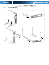
INSTALLING YOUR UPS SYSTEM
SYSTEM BLOCK DIAGRAM
HARDWARE INSTALLATION GUIDE
1. Battery charge loss may occur during shipping and storage. Before using the UPS, it’s strongly
recommended to charge batteries for four hours to ensure the batteries’ maximum charge capacity. To
recharge the batteries, simply connect the UPS to its designated AC electrical service.
2. When using PowerPanel® Business Edition software, connect either the serial or the USB cable between
the computer and the corresponding port on the UPS. Note: If the USB port is used, the serial port will
be disabled. They cannot be used simultaneously. After connecting to either the USB port or the serial
port on the UPS, a computer with PowerPanel® Business Edition Agent software installed can control
the operating schedule, battery test, outlets, as well as obtain UPS status information. However, other
computers with PowerPanel® Business Edition Client software can only obtain UPS status information
via LAN connection.
3. Connect your computer, monitor, and any externally-powered data storage device (Hard drive, Tape
drive, etc.) into the outlets only when the UPS is o and unplugged. DO NOT plug a laser printer, copier,
space heater, vacuum, paper shredder or other large electrical device into the UPS. The power demands
of these devices will overload and possibly damage the unit.
4. To protect a fax machine, telephone, modem line or network cable, connect the telephone or network
cable from the wall jack outlet to the jack marked “IN” on the UPS and connect a telephone cable
or network cable from the jack marked “OUT” on the UPS to the modem, computer, telephone, fax
machine, or network device.
5. Press the ON/OFF switch to turn the UPS on. The Power-On indicator LED will turn on when activated.
If an overload is detected, an audible alarm will sound and the UPS will continuously emit two beeps
per second. For resetting the unit, unplug some equipment from the outlets. Make sure your equipment
carries a load current within the unit’s safe range, (refer to the technical specifications).
6. This UPS is equipped with an auto-charge feature. When the UPS is connected to AC electrical service
the battery will automatically charge, even when the unit is switched o.
Output
Input
Filter
PFC
AC/DC
BUS
Inverter
DC/AC
STS
Charger
AC/DC
Bypass
Battery
Output
Filter
Input
Line Mode
Battery Mode
Bypass Mode
Control
&
Monitoring
LCD Module
USB & DB9
SNMP Slot

įĂĀĂĀƫ5!.ƫ+3!.ƫ5/0!)/ƫĨĩČƫ*ċƫ((ƫ.%#$0/ƫ.!/!.2! ċƫ((ƫ+0$!.ƫ0. !).'/ƫ.!ƫ0$!ƫ,.+,!.05ƫ+"ƫ0$!%.ƫ.!/,!0%2!ƫ+3*!./ċƫ
7
INSTALLING YOUR UPS SYSTEM CONT.
HARDWARE INSTALLATION GUIDE CONT.
7. To maintain an optimal battery charge, leave the UPS connected to AC electrical service at all times.
8. Before storing the UPS for an extended period of time, turn the unit OFF. Then cover it and store it with
the batteries fully charged. Recharge the batteries every three months to ensure good battery capacity
and long battery life. Maintaining a good battery charge will help prevent possible damage to the unit
from battery leakage.
9. The UPS has one USB port (default) and one serial port that allows connection and communication
between the UPS and any attached computer running PowerPanel® Business Edition Agent software.
The UPS can control the computer’s shutdown during a power outage through the connection while
the computer can monitor the UPS and alter various programmable parameters. Note: Only one
communication port can be used at a time. The port not in use will automatically become disabled or
the serial port will be disabled if both ports are attached.
10. EPO (Emergency Power O) Port: EPO ports allow administrators the capability to connect the UPS
unit to customer-supplied EPO switches. These installations give operators a single access point to
immediately power-o all equipment connected to the UPS during an emergency.
11. To avoid electric shock, turn the unit OFF and disconnect the unit from utility power before hardwiring
the UPS (in/out power cord). The in/out power cord MUST be grounded.
12. Please note the internal UPS temperature will increase when fans are not in operation or ventilation is
obstructed. When the high temperature sensor activates protection, the UPS generates an alarm and
shuts down to avoid unexpected equipment damage. When the over temperature occurs, please check
the Troubleshooting section. If the condition persists, please contact CyberPower for technical support.

įĂĀĂĀƫ5!.ƫ+3!.ƫ5/0!)/ƫĨĩČƫ*ċƫ((ƫ.%#$0/ƫ.!/!.2! ċƫ((ƫ+0$!.ƫ0. !).'/ƫ.!ƫ0$!ƫ,.+,!.05ƫ+"ƫ0$!%.ƫ.!/,!0%2!ƫ+3*!./ċƫ
8
HARDWARE INSTALLATION
CyberPower UPS systems can be installed in a rackmount or vertical/tower orientation. This versatility
is especially important to growing organizations with changing needs that value having the option to
position a UPS on the floor or in a rackmount system. Note that the included rack mounting hardware is
only compatible with square hole racks. Please follow the instructions below for the respective mounting
methods.
RACKMOUNT INSTALLATION
To prevent the risk of fire or electric shock, only use the supplied hardware to attach the mounting brackets.
Step 1: Remove the dust covers
Remove ten dust covers from the screw holes as shown below.
Step 2: Rackmount ear & hanging bracket installation
Attach two rackmount ears to the UPS using eight black M5X7L flat head screws and tighten two hanging
brackets using six silver M5X6L pan head screws.
Step 3: Rackmount rail Installation
The mounting depth of the included rackmount rails can adjust from 20.5 in to 36 in (52 cm to 91.5 cm).
Select the proper holes in the rack for positioning the UPS in the rack. The UPS takes up 3 rack units: rack
hole positions 1 through 9.
Position the guide screws on the back of the rackmount rails into the rear rack square holes to temporarily
support the rails in place.
Step 4: Adjust rackmount rails to fit your rack
Adjust the rail depth to match your rack depth. Attach each rackmount rail to your rack with two black
M5X6L pan head screws and two plastic washers at the front of the rack (square holes 4 and 8 as shown
below). Secure each rail to the rear of the rack with two black M5X6L pan head screws and two plastic
washers.
1 2
Caution: Important Instructions

įĂĀĂĀƫ5!.ƫ+3!.ƫ5/0!)/ƫĨĩČƫ*ċƫ((ƫ.%#$0/ƫ.!/!.2! ċƫ((ƫ+0$!.ƫ0. !).'/ƫ.!ƫ0$!ƫ,.+,!.05ƫ+"ƫ0$!%.ƫ.!/,!0%2!ƫ+3*!./ċƫ
9
1
2
3
4
5
6
7
8
9
2U
3U
4U
1U
HARDWARE INSTALLATION CONT.
RACKMOUNT INSTALLATION: RACKMOUNT EARS INSTALLATION CONT.
Step 5: Place and secure the UPS on the rails
Slide the hanging brackets on the UPS on to the rails mounted in the rack with the front of the unit facing
toward you. Secure the UPS to your rack with four black M5X12L pan head screws at the front of the rack
(square holes 5 and 7 as shown above).
Once completed, perform the same steps for the Battery module. Remove the internal battery trays from
the Battery module before installing it. (See Battery Replacement section) The Battery module must be
installed below the Power module. Place the internal battery trays back into the Battery module after
installation. (See Battery Replacement section)
NOTE: To slide the UPS out from the rack
The UPS will be secured by a safety locking mechanism midway of pulling it out of the rack. Use both hands
to hold the UPS and press the safety locking tab to pull the UPS out.
3 4
5
Rackmount ear
Rackmount rail
SRVLWLRQ
SRVLWLRQ
SRVLWLRQ
SRVLWLRQ
SRVLWLRQ
SRVLWLRQ

įĂĀĂĀƫ5!.ƫ+3!.ƫ5/0!)/ƫĨĩČƫ*ċƫ((ƫ.%#$0/ƫ.!/!.2! ċƫ((ƫ+0$!.ƫ0. !).'/ƫ.!ƫ0$!ƫ,.+,!.05ƫ+"ƫ0$!%.ƫ.!/,!0%2!ƫ+3*!./ċƫ
10
VERTICAL/TOWER INSTALLATION
Step 1: Adhere rubber pads
Adhere the protective rubber pads to the left hand side of the UPS power module and extended battery
module.
Step 2: Attach the base stands and attach the dust covers
Stand the UPS power module and extended battery module on its side. Secure the tie bracket on top of the
power module and extended battery module with four black M5X7L flat head screws. Insert dust covers
into the screw holes that are not being used. Optionally, use the rack mount ears as tower stands. Screw
them onto the power module and extended battery module with four black M5X6L pan head screws for
adding stability.
Step 3: Rotate the Multifunction LCD Control Panel
Unscrew the upper panel of the UPS. Separate the upper panel from the UPS. Gently lift the LCD control
panel out. Rotate it to the tower orientation. Reinstall it for a tower configuration.
HARDWARE INSTALLATION CONT.
3
1
2

įĂĀĂĀƫ5!.ƫ+3!.ƫ5/0!)/ƫĨĩČƫ*ċƫ((ƫ.%#$0/ƫ.!/!.2! ċƫ((ƫ+0$!.ƫ0. !).'/ƫ.!ƫ0$!ƫ,.+,!.05ƫ+"ƫ0$!%.ƫ.!/,!0%2!ƫ+3*!./ċƫ
11
Verify branch circuit breaker rating and wiring dimensions with the following table for hardwired input
UPS models.
INPUT/OUTPUT CONFIGURATION
Hardwire the input/output terminals as shown in the following diagram.
Input and Output circuit breakers must be “OFF” during the installation process.
An additional two pole disconnect device is necessary during the installation process.
Disconnected EPO will immediately shut down the logic circuit output of the UPS. Wiring the EPO port is
optional.
Local safety rules may require a separate, external EPO to turn o output circuit breakers. Refer to local
wiring rules, the EPO should use approved components.
OL6KRT Electrical Connection
Connect the NEMA L6-30P input power cord on the UPS to a properly wired NEMA L6-30R outlet. See the
Extended Battery Module Installation section for instruction on connecting the battery module to the UPS.
UPS CAPACITY
BRANCH CIRCUIT
BREAKER
WIRING AWG WIRING mm
2
6K VA 40A 10 AWG 5.5 mm
2
8KVA 50A 8 AWG 8.0 mm
2
10KVA 70A 6 AWG 14.0 mm
2
Caution: Important Instructions
ELECTRICAL INSTALLATION
UPS
PFC
AC/DC
Inverter
DC/AC
STS
L1 L2 PE
Input
Circuit Breaker
Wiring
AWG
Wiring
AWG
L1 L2 PE
External
EPO
OutputMains
Battery
L2
L1
PE
L2
L1
PE

įĂĀĂĀƫ5!.ƫ+3!.ƫ5/0!)/ƫĨĩČƫ*ċƫ((ƫ.%#$0/ƫ.!/!.2! ċƫ((ƫ+0$!.ƫ0. !).'/ƫ.!ƫ0$!ƫ,.+,!.05ƫ+"ƫ0$!%.ƫ.!/,!0%2!ƫ+3*!./ċƫ
12
INPUT/OUTPUT CONFIGURATION CONT.
OL8KRT and OL10KRT Electrical Connection
Step 1: Separate the terminal block cover
Loosen the two screws joining the top and bottom terminal block covers to separate them.
Step 2: Secure the bottom cover on to the UPS
Tighten the two screws to secure the bottom cover on to the UPS terminal block.
Step 3: Input configuration
Insert the input cable through the appropriate cable gland (not included) and connect the three wires to
the input terminal block.
Step 4: Output configuration
Insert the output cable through the appropriate cable gland (not included) and connect the three wires to
the output terminal block.
Step 5: Secure the top cover
Use four screws to secure the top terminal block cover on to the UPS.
BACKFEED PROTECTION OPERATION
1. If the Bypass circuit is shorted and the UPS is running in Line Mode or Battery Mode, backfeed
protection will be active and the external isolation device (Magnetic Contactor) will open.
2. Save your data and perform a controlled shutdown.
3. Contact CyberPower for repair.
4 5
ELECTRICAL INSTALLATION CONT.
1
2 3
Warning!
A CyberPower Step-Down Transformer is required for supplying 120V output to connected equipment. To
prevent damage to connected equipment, do not attempt to separate the output voltage, from the hardwire
block or outlets, into two 120V outputs on this UPS. If you attempt to supply two separate 120V outputs to
your equipment, that equipment can be damaged when the UPS switches to battery mode.
L2
L1
AC INPUT AC OUTPUT
L2
L1
Input/Output Terminal
Block Diagram

įĂĀĂĀƫ5!.ƫ+3!.ƫ5/0!)/ƫĨĩČƫ*ċƫ((ƫ.%#$0/ƫ.!/!.2! ċƫ((ƫ+0$!.ƫ0. !).'/ƫ.!ƫ0$!ƫ,.+,!.05ƫ+"ƫ0$!%.ƫ.!/,!0%2!ƫ+3*!./ċƫ
13
WITHOUT BACKFEED PROTECTION CONFIGURATION
1. Hardwire the input terminals as shown in the following diagram.
2. Do not remove the interconnection wires (Jumper1 / Jumper2) on “Backfeed Protection Connector”.
WITH BACKFEED PROTECTION CONFIGURATION
1. Connect a user supplied external isolation device (Magnetic Contactor) upstream and outside the UPS
and capable of supporting the UPS input current.
2. Remove the interconnection wires (Jumper1 / Jumper2) on “Backfeed Protection Connector”.
3. Hardwire the input terminals and “Backfeed Protection Connector” as shown in the following diagram.
4. The external isolation device must be installed in the Mains path.
UPS
L1
L2
PSDR
AC-L1
AC-L2
IP-L1
IP-L2
Backfeed
1
2
4
5
3
L1
L2
I/P
EMI
L1
L2
L1 L2 PE
Mains
PE
Jumper2
Jumper1
UPS
L1
L2
PSDR
AC-L1
AC-L2
IP-L1
IP-L2
Backfeed
1
2
3
4
5
MC
L1
L2
L1
L2
A1
A2
I/P
EMI
L1
L2
L1
L2
L1 L2 PE
Mains
PE
2A Fuse
(Slow Blow)
ELECTRICAL INSTALLATION CONT.

įĂĀĂĀƫ5!.ƫ+3!.ƫ5/0!)/ƫĨĩČƫ*ċƫ((ƫ.%#$0/ƫ.!/!.2! ċƫ((ƫ+0$!.ƫ0. !).'/ƫ.!ƫ0$!ƫ,.+,!.05ƫ+"ƫ0$!%.ƫ.!/,!0%2!ƫ+3*!./ċƫ
14
EXTENDED BATTERY MODULE INSTALLATION
REAR PANEL DESCRIPTION
1. On-board Replaceable Fuse Cover
Replaceable fuse is accessible from the rear panel. Service to be performed by qualified personnel only.
2. AC Circuit Breaker
Provides overload and fault protection.
3. AC Output Outlet (IEC320 C13)
Use this outlet to connect to the AC Input Inlet of a downstream Battery module.
4. AC Input Inlet (IEC320 C14, Charge Only)
Connection for separate AC power source for Fast Charge Technology feature. NOT to be connected to
UPS output as source of power.
5. Battery DC Input Connector
Use this input connector to daisy chain the next Extended Battery Module. Remove the connector cover
for access.
6. Battery DC Output Cable
Use this output cable to connect the Extended Battery Module to the Power module or to the next
Extended Battery Module.
7. Use the DC breaker to disconnect battery output.
CONNECTION WITH POWER MODULE
Scenario #1: Power module with one Extended Battery
Module (EBM)
)86(
$
9a
&KDUJH2QO\
$&,1387
$&287387
9
%$77(5<,1387
%$77(5<287387
9
3 6 72 51 4
BP240VL3U01 / BP240VL3U02
PLUG INTO A
WALL
RECEPTACLE
RELAY
OUTPUT
OUT
IN
USB
RS232
BACK-FEED PROTECTION
CONNECTOR
BATTERY INPUT : 240V
EPO
INTERFACE
FUSE
250V~
10A
AC INPUT
(Charge Only)
AC OUTPUT
240V
BATTERY OUTPUT
BATTERY INPUT
240V
1
OUTPUT BREAKER
30A/250V~
OUTPUT BREAKER
30A/250V~
NONCRITICAL
LOAD
2
1
CRITICAL LOAD
4
3
INPUT BREAKER
63A / 250V~
/