DeWalt DW7440RS User manual

Category
Circular saws
Type
User manual

This manual is also suitable for

DW7440RS
Heavy-Duty Rolling Table Saw Stand
Socle mobile robuste pour table de scie
Base rodante para sierra banco, para trabajo pesado
INSTRUCTIVO DE OPERACIƓN, CENTROS DE SERVICIO Y PƓLIZA
DE GARANTƍA. ADVERTENCIA: LƉASE ESTE INSTRUCTIVO
ANTES DE USAR EL PRODUCTO.
INSTRUCTION MANUAL
GUIDE D'UTILISATION
MANUAL DE INSTRUCCIONES
If you have questions or comments, contact us.
Pour toute question ou tout commentaire, nous contacter.
Si tiene dudas o comentarios, contƔctenos.
1-800-4-DEWALT ā€¢ www.dewalt.com
1
English
A. Axle
B. Leg supports
C. Wheels
D. Saw mounting bracket
E. Bracket release levers
F. Leg release levers
G. Locking pins
H. Legs
I. Beams
J. Locator clip
K. Handle
L. Handle lock
M. Rubber bumpers
N. Kickstand
O. Tube plugs
DW7440RS
Heavy-Duty Rolling Table Saw Stand
F
I
H
K
G
D
J
L
M
E
E
D
O
N
A
B
C
D
D
E
K
I
E
H
B
N
2
English
IF YOU HAVE ANY QUESTIONS OR COMMENTS ABOUT THIS
OR ANY D
EWALT TOOL, CALL US TOLL FREE AT:
1-800-4-D
EWALT (1-800-433-9258)
DW7440RS Rolling Table Saw Stand
with Folding Legs
WARNING: For your own safety, read the table saw instruction
manual before using any accessory. Failure to heed these warnings
may result in personal injury and serious damage to the table saw
and the accessory. When servicing this tool, use only identical
replacement parts.
This stand is designed for use with table saws only. The DW7440RS
is approved for use with the DW744, DW744X and the DW745 table
saws. If you experience a problem with your D
EWALT purchase,
please call 1-800-4-D
EWALT (1-800-433-9258).
Tools Required
Phillips screwdriver
Socket or wrench set
Contents
Stand Carriage head bolts (2)
Mounting brackets (2) M8 lock nuts (4)
Wheels (2) Rear axle
Rubber bumpers (2) M4 screws (2)
Washers (4) M4 lock nuts (2)
Kickstand assembly M6 screws (4)
Tube plugs (2) M4 hex wrench
Saw mounting hardware: hex head bolts (4), washers (8),
nuts (4), lock washers (4)
General Safety Instructions for Table
Saw Accessories
WARNING: To reduce the risk of personal injury:
ā€¢ ALWAYS use eye protection. All users and bystanders must
wear eye protection that conforms to ANSI Z87.1.
ā€¢ Ensure all stand fasteners are securely fastened and that all
stand mechanisms are in proper working order before operating
the table saw.
ā€¢ DO NOT exceed the weight this stand can hold. The DW7440RS
table saw stand is designed to support 150 lbs. (68 kgs.) safely
in a work environment. It is unsafe to climb, sit or stand on the
stand.
Definitions: Safety Guidelines
The definitions below describe the level of severity for each
signal word. Please read the manual and pay attention to
these symbols.
DANGER: Indicates an imminently hazardous situation
which, if not avoided, will result in death or serious injury.
WARNING: Indicates a potentially hazardous situation
which, if not avoided, could result in death or serious
injury.
CAUTION: Indicates a potentially hazardous situation
which, if not avoided, may result in minor or moderate
injury.
CAUTION: Used without the safety alert symbol indicates
a potentially hazardous situation which, if not avoided, may
result in property damage.
3
English
ā€¢ Follow the mounting instructions carefully. Fasten the tool to the
saw mounting brackets securely as instructed.
ā€¢ DO NOT modify or use stand for operations for which it is
unintended.
ā€¢ DO NOT use the stand on uneven surfaces. DO NOT use the
stand with the legs folded and stand sitting on the ground. The
stand is designed to be used on a flat, stable surface.
ASSEMBLY
Attaching the Wheels and Axle
1. Attach the axle (A) to
B
A
the leg support (B) by
aligning the pre-drilled
holes. Ensure the long end
of the axle is to the rear of
the stand as shown. Secure
axle to leg support using
two carriage bolts, washers
and lock nuts provided.
2. Place the wheels (C) on
the axle and secure with
washers and lock nuts as
shown. Tighten wheel and
axle nuts securely.
Attaching the
Kickstand
Insert the tube plugs (O) into the end of the kickstand tube (N). The
groove in the tube plug should be facing down as shown. Be sure
that the holes (P) in the tube plugs are in line with the holes (Q) in
the kickstand tube before inserting the tube plugs.
Insert the kickstand tube (N) through
O
N
Q
P
the holes in the leg support (B) on
the wheel-axle side of the stand.
Be sure the kickstand is pointing
up when the stand is an upright
position. Secure the kickstand to
the beams (I) with the four M6
screws provided as shown (below,
left).
The hex wrench may be stored in the end of the tube plug as shown
for future use.
B
N
Attaching the
M
Rubber Bumpers
Attach the two rubber
bumpers (M) to the
handle side leg support as
shown using the M4 screws
and lock nuts provided.
4
English
Table Saw Bracket Mounting
WARNING: To reduce the risk of injury, turn unit off,
disconnect machine from power source before assembling
the table saw to the table saw stand. An accidental start-up can
cause injury.
WARNING: For your own safety, read and understand the table
saw instruction manual before using. Failure to heed these warnings
may result in personal injury and serious damage to the table saw
and the accessory.
WARNING: The saw mounting brackets provided with this stand
are equipped with lever locks. To reduce the risk of injury, DO NOT
modify the mounting bracket lever locks.
1. Unfold the legs by depressing
G
H
F
R
the leg release levers (F).
Rotate the legs until the
locking pin (G) clicks into its
detent (R).
2. Turn the stand upright. The
stand should be stable and
should not rock.
WARNING: Be sure that
the locking pins have
engaged and the legs
J
E
are firmly held in place.
3. The locator clip (J)
keeps the saw from sliding
left or right during cutting
operations and during
transport. Install the mounting
brackets on to the beam as
shown by engaging the
concave front lip of the
mounting bracket with the
E
D
rounded front edge of the
beam. One of the brackets
must engage the locator
clip (J). The mounting
bracket release levers
(E) must be positioned to
the rear of the stand as
shown.
4. Measure the distance
between the mounting
holes of the table saw.
Position the second
mounting bracket onto
the beam at this distance
from the first mounting
bracket.
5. Align the holes in the table
saw base with the slots in the
saw mounting brackets (D).
6. Feed a hex head bolt with flat
washer installed through each
of the four holes in the table saw
base and mounting brackets.
Secure each location with a flat
washer, lock washer and nut
provided.
WARNING: To reduce the risk of personal injury, be sure the table
saw is fully anchored on the stand.
WARNING: The table saw must be positioned on the tool mount
so that all four corners can be bolted to the mounting brackets. If the
saw is mounted properly, the mounting brackets will be positioned
perpendicular to the stand rail when the saw is placed on the stand.
5
English
Please call DEWALT customer support at 1-800-4-DEWALT if you
need assistance.
To Detach the Saw from the Stand
WARNING: To reduce the
E
risk of injury, turn unit off,
disconnect machine from
power source before detaching
the table saw from the table
saw stand. An accidental start-
up can cause injury.
The saw mounting brackets
included with the DW7440RS
stand are equipped with rubber
feet that can support the saw
when cutting on a work area
without a stand.
TO REMOVE THE SAW FOR
CARRYING OR FOR USE
E
K
L
WITHOUT THE STAND
1. Reach around the sides
of the saw and grasp the
release levers (E).
2. Pull up slightly to clear
the beam and tilt the saw
toward you to carry.
TO REATTACH THE SAW
AND SAW MOUNTING
BRACKETS TO THE STAND
1. Grip the table saw table
as shown while facing the
front of the saw.
2. Position the left-hand side mounting bracket into the locator clip.
3. When the front concave lip of both mounting brackets are
engaged with the front round edge of the beam, pivot the
saw back and down allowing the release levers (E) to click
into place on the rear beam. Rock the saw gently to verify the
mounting brackets are locked onto the beams.
4. If the handle (K) has been extended, pull the handle lock (L)
down to release the handle and then slide the handle in for
storage or saw usage.
TO ATTACH D
EWALT DW745 TABLE SAW TO THE SAW
MOUNTING BRACKETS
1. Remove the front feet bolts and the front rubber feet from the
DW745 table saw.
2. Remove the rear feet from the rear frame bar of the saw.
3. Retain these components for future use.
4. Feed a hex head bolt with flat washer installed through each of
the four holes in the frame bars where the removed front and
rear feet were previously installed. Secure each location with a
flat washer, lock washer and nut provided.
WARNING: To reduce the risk of personal injury, NEVER use the
table saw with the handle extended. An extended handle creates an
unsafe work area.
WARNING: To reduce the risk of personal injury, do not hang
objects from the handle. The stand may tip when downward force
is applied.
Transporting the Saw on the Stand
COLLAPSING THE STAND FOR TRANSPORT
1. Place one hand under the leg support and hold the legs slightly
off the ground.
6
English
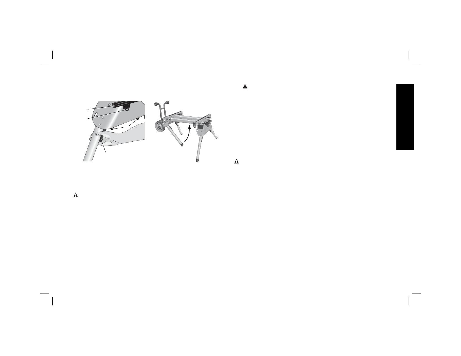
2. Depress the leg release lever (F) with the other hand then push
the leg under the beam on the stand. Repeat the operation on
the second leg of the stand and rest the stand on wheels.
M
K
L
F
3. Repeat with the other end of the stand.
4. Pull the extendable handle (K) out of the side of the stand. The
spring-loaded handle lock (L) will lock the handle into position for
transporting the saw on the stand. Pull the handle lock down to
release the handle and then slide the handle in for storage.
WARNING: To reduce the risk of personal injury, DO NOT operate
the table saw mounted to the stand with the legs folded and the
stand sitting on the ground.
To Raise Stand from Collapsed Position
Roll the stand to the workspace. Be sure the area is flat and stable
before attempting to set up the saw and stand.
1. Tilt up the stand until the saw is at a 45 degree angle.
2. Depress the leg release levers one at a time to release the
locking pins and pull the front legs out until each locking pin
clicks into the detent.
WARNING: Be sure that the locking pins have engaged and
the legs are firmly held in place.
3. Rest the stand on the legs.
4. Depress the handle lock to release the handle. Slide the handle
into the leg support for storage as you work.
5. Go to the opposite side of the stand and grasp the saw under the
rear axle. Lift the saw and stand.
6. Reach under the stand and, one at a time, depress the leg
release levers to release the locking pins. Pull out the remaining
two legs. Be sure that the locking pins have engaged and the
legs are firmly held in place. Rest the stand on the ground.
Accessories
WARNING: Since accessories, other than those offered by
D
EWALT, have not been tested with this product, use of such
accessories with this tool could be hazardous. To reduce the risk of
serious injury, place stand on flat, stable surface. DO NOT create
unstable conditions.
Recommended accessories for use with your tool are available at
extra cost from your local dealer or authorized service center. If you
need assistance in locating any accessory, please contact D
EWALT
Industrial Tool Co., 701 East Joppa Road, Baltimore, MD 21286,
call 1-800-4-D
EWALT (1-800-433-9258) or visit our website www.
dewalt.com.
Repairs
To assure product SAFETY and RELIABILITY, repairs, maintenance
and adjustments should be performed by a D
EWALT factory service
center, a D
EWALT authorized service center or other qualified
service personnel. Always use identical replacement parts.
7
English
Three Year Limited Warranty
DEWALT will repair, without charge, any defects due to faulty
materials or workmanship for three years from the date of purchase.
This warranty does not cover part failure due to normal wear or
tool abuse. For further detail of warranty coverage and warranty
repair information, visit www.dewalt.com or call 1-800-4-D
EWALT
(1-800-433-9258). This warranty does not apply to accessories or
damage caused where repairs have been made or attempted by
others. This warranty gives you specific legal rights and you may
have other rights which vary in certain states or provinces.
In addition to the warranty, D
EWALT tools are covered by our:
1 YEAR FREE SERVICE
D
EWALT will maintain the tool and replace worn parts caused by
normal use, for free, any time during the first year after purchase.
90 DAY MONEY BACK GUARANTEE
If you are not completely satisfied with the performance of your
D
EWALT Power Tool, Laser, or Nailer for any reason, you can return
it within 90 days from the date of purchase with a receipt for a full
refund ā€“ no questions asked.
LATIN AMERICA: This warranty does not apply to products sold
in Latin America. For products sold in Latin America, see country
specific warranty information contained either in the packaging, call
the local company or see website for warranty information.
FREE WARNING LABEL REPLACEMENT: If your warning labels
become illegible or are missing, call 1-800-4-D
EWALT for a free
replacement.
DEWALT Industrial Tool Co., 701 East Joppa Road, Baltimore, MD 21286 (FEB08) Part No. 648674-00 DW7440RS
Copyright Ā© 2007, 2008 D
EWALT
The following are trademarks for one or more D
EWALT power tools: the yellow and black color scheme; the ā€œDā€ shaped air intake grill; the
array of pyramids on the handgrip; the kit box configuration; and the array of lozenge-shaped humps on the surface of the tool.
  • Page 1 1
  • Page 2 2
  • Page 3 3
  • Page 4 4
  • Page 5 5
  • Page 6 6
  • Page 7 7
  • Page 8 8
  • Page 9 9
  • Page 10 10
  • Page 11 11
  • Page 12 12
  • Page 13 13
  • Page 14 14
  • Page 15 15
  • Page 16 16
  • Page 17 17
  • Page 18 18
  • Page 19 19
  • Page 20 20
  • Page 21 21
  • Page 22 22
  • Page 23 23
  • Page 24 24

DeWalt DW7440RS User manual

Category
Circular saws
Type
User manual
This manual is also suitable for

Ask a question and I''ll find the answer in the document

Finding information in a document is now easier with AI