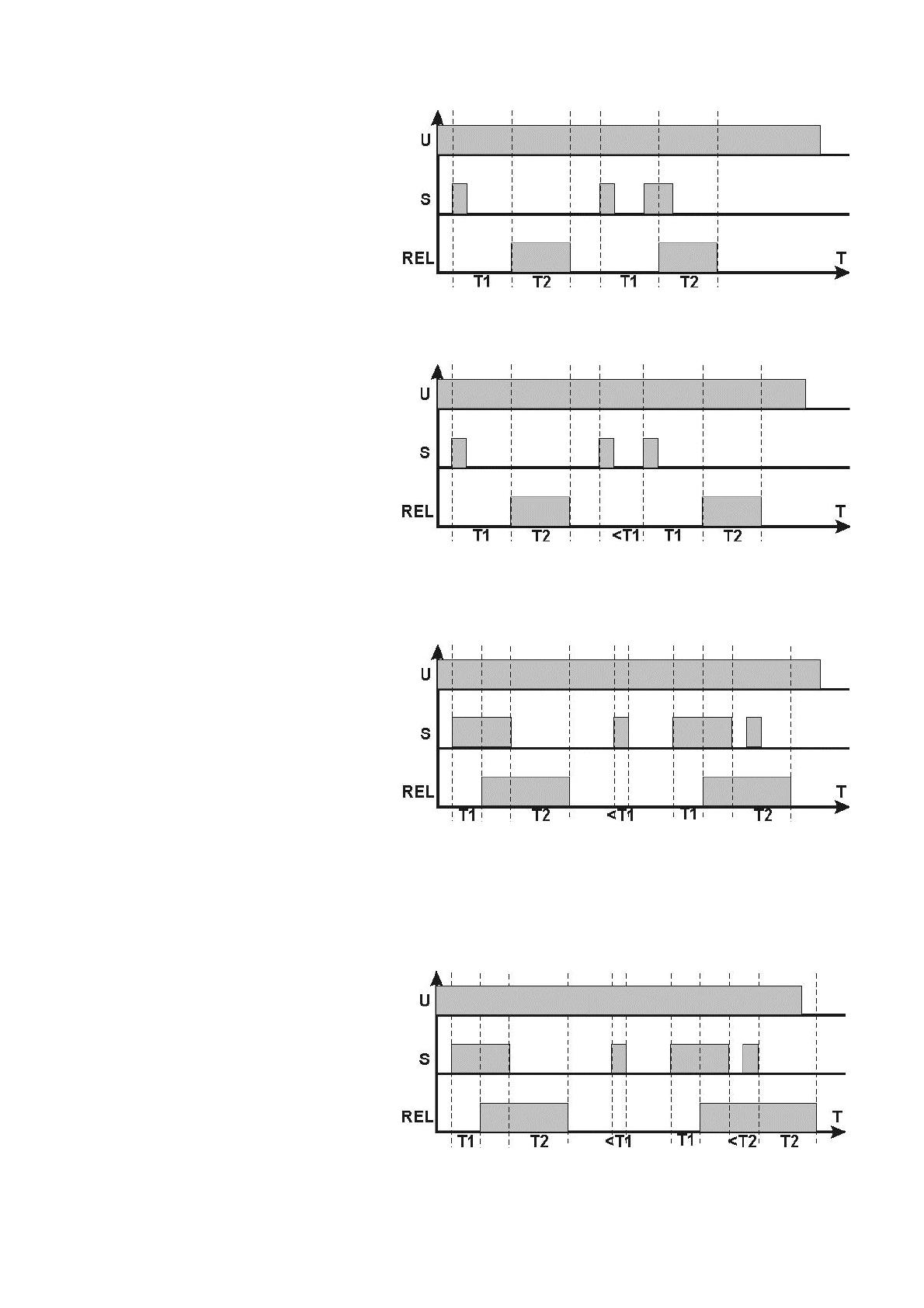
Pulsar AWZ516 - v2.1 User manual

Type
User manual

This manual is also suitable for

1
AWZ516
v.2.1
PC1
Time relay module.
Edition: 5 from 01.03.2018 EN*
Supersedes the edition: 4 from 15.01.2015
Features:
10 ÷ 16V DC power supply
18 time-logic programs
The range of measured times: up to 100 hours
High precision time measurements
High load capacity of relay contacts
LED display
Three function buttons
Activated by plus "S +" or mass "S-"
Reset input activated by mass "R-"
Optical indication of power supply and relay output status
The possibility of implementing additional time-logic programs
Warranty - 2 year from the production date
TABLE OF CONTENTS.
1. General description. ....................................................................................................................................... 1
2. Components arrangement. ............................................................................................................................ 2
3. Programming the time module. ..................................................................................................................... 3
4. Preview - the parameters of currently set program. .................................................................................... 4
5. Previewing the status. .................................................................................................................................... 4
6. Timer programs. .............................................................................................................................................. 5
7. Programming example. ................................................................................................................................ 10
The time module is factory set to PR0 program mode with active REL relay.
1. General description.
The PC1 time module is a transceiver allowing execution of time-logic programs. The device is
characterized by versatility, high accuracy of the measured time based on the crystal oscillator and the possibility
of its precise and repeatable adjustment. The relay can be used to extend short control impulses, e.g. controlling
the operation locks, electromagnetic jumpers, bistable control, etc. The relay is used in automation and control
circuits and access control projects, with logical dependencies on the state of: the controller, door opening sensor
(reed switch), exit button, etc.
2
2. Components arrangement.
The figure below shows the arrangement of the most important components and connectors of the relay
module.
Fig. 1. The module’s view.
Table 1. The description of components and connectors of the module.
Number
[Fig. 1]
Description
Connector:
+12V- - the module’s power supply, DC voltage
S+ - control input supplied by the positive power supply
S- - control input activated by negative power supply (ground)
R- - reset input activated by negative power supply (ground)
LEDs optical indication
red supply voltage
REL ON, relay on
PR blinking programming mode, ON previewing the current mode
T1 time indication T1
T2 time indication T2
h hours indication (0-99h)
m minutes indication (0-59m)
s seconds indication (0-59s)
LED display.
Relay
Buttons
- Decreasing the parameter, move down one level in the menu
- Increasing the parameter, move up one level in the menu
OK. - Confirm the settings
The REL relay connector
CAUTION! Connector pin-out in the figure 1 shows the potential-free status of the relay.
3
3. Programming the time module.
If there is no action for more than 30 seconds when changing the parameters settings, the module
automatically exits the programming mode without saving the changes.
1) Press the and buttons simultaneously for 5 seconds to enter
the programming mode.
The „PR” LED will blink and the number of currently saved
program will be displayed.
2) Use the or buttons to select the desired program number.
Confirm by pressing "OK.” button.
3) Use the or buttons to set the „T1” time (hours).
(when required).
The „T1” and „h” LEDs are ON.
Confirm by pressing OK.” button.
4) Use the or buttons to set the „T1” time (minutes).
The „T1” and „m” LEDs are ON.
Confirm by pressing „OK.” button.
5) Use the or buttons to set the „T1” time (seconds).
The „T1” and „s” LEDs are ON.
Confirm by pressing „OK.” button.
6) Use the or buttons to set the „T2” time (hours)
(when required).
The „T2” and „h” LEDs are ON.
Confirm by pressing „OK.” button.
7) Use the or buttons to set the „T2” time (minutes).
The „T2” and „m” LEDs are ON.
Confirm by pressing „OK.” button.
8) Use the or buttons to set the „T2” time (seconds).
The „T2” and „s” LEDs are ON.
Confirm by pressing „OK.” button.
9) The scrolling message „ready” - indicating readiness for operation
of the module according to the selected mode and preset times
will be displayed
4
4. Preview - the parameters of currently set program.
The program number and time module parameters can be checked by pressing the OK button for 3
seconds. The "PR" LED will light up and the number of the currently set program will be displayed.
Use the or buttons. The information about the current time parameters of the program -
according to the diagram in Chapter 3: "Programming the time module” will be displayed.
The Preview Mode is disabled once the OK button is pressed again or after 5 seconds of inactivity.
5. Previewing the status.
During normal operation, it is possible to preview the time module operating status. Press the or
button; the following information is displayed as follows:
Countdown timer - hours
The “h” and “T1” or “T2” LED is ON
Countdown timer - minutes
The “m” and “T1” or “T2” LED is ON
Countdown timer - seconds
The “s” and “T1” or “T2” LED is ON
Preview of the status of R and S inputs
A blinking dot indicates the time measurement
of operating module
5
6. Timer programs.
PR0 - Permanent on or off.
In this mode, press the
"OK" button to permanently
switch on or off the relay.
The relay state is
remembered when power is
disconnected and it is
immediately restored when
switched on.
PR1 - T1 time activation delay with locking option single cycle.
The countdown of the T1 time takes
place automatically after switching on
the power. Then, the "REL" relay is
activated. This mode is maintained until
the power is disconnected.
In the case of the S triggering
signal (rising edge) during the
countdown of the T1 time, the module
will lock and the relay will not be
activated.
PR2 - T1 time deactivation delay with locking option single cycle.
The "REL" relay is activated
automatically after switching on the
power for the T1 time period. Once the
countdown of the T1 time is finished, the
"REL" relay is disconnected. This mode
is maintained until the power is
disconnected.
In case of theS” triggering signal
(rising edge) during the countdown of
the T1 time, the module will lock and the
relay will not be deactivated.
PR3 - T1 to T2 time activation delay with resetting T1 time single cycle.
The countdown of the T1 time takes
place automatically after switching on
the power. Then, the "REL" relay is
activated for the T2 time period. Once
the countdown of the T2 time is finished,
the "REL" relay is disconnected. This
mode is maintained until the power is
disconnected.
The S” triggering signal (rising
edge) during the countdown of the T1
time resets and restarts the T1
countdown process.
6
PR4 - T1 to T2 time deactivation delay with resetting T1 time single cycle.
The "REL" relay is activated
automatically after switching on the
power for the T1 time period. Then, the
"REL" relay is deactivated for the T2
time period. Once the countdown of the
T2 time is finished, the "REL" relay is
activated again. This mode is
maintained until the power is
disconnected.
The „S triggering signal (rising
edge) during the countdown of the T1
time resets and restarts the T1 countdown process.
PR5 - Activation delay with increasing T2 activation time with Ts time cyclic.
The countdown of the T1 time takes
place automatically after switching on
the power. Then, the "REL" relay is
activated for the T2 time period. This
mode is repeated cyclically.
In case of the S” signal (level)
during the countdown of the T2 time,
the countdown is extended by the
duration of the S signal.
The countdown is extended only
during the countdown of the T2 time.
PR6 - Deactivation delay with increasing T2 deactivation time with Ts time cyclic.
The countdown of the T1 time takes
place automatically after switching on
the power. Then, the "REL" relay is
deactivated for the T2 time period. This
mode is repeated cyclically.
In case of the „S signal (level)
during the countdown of the T2 time, the
countdown is extended by the duration
of the S” signal.
The countdown is extended only
during the countdown of the T2 time.
PR7 Bistable mode.
In case of theS” triggering signal
(rising edge), the REL relay is
immediately switched into opposite
state.
7
PR8 Increasing the impulse to T1 time from rising edge.
The S triggering signal (rising
edge) immediately activates the "REL"
relay for the T1 time period. Once the
countdown of the T1 time is finished,
the "REL" relay is deactivated.
Another S” triggering signal during
the countdown of the T1 time will not
affect the countdown until activation of
the REL” relay.
PR9 - Increasing the impulse to T1 time from rising edge with resetting T1 time.
The S” triggering signal (rising
edge) immediately activates the "REL"
relay for the T1 time period. Once the
countdown of the T1 time is finished, the
"REL" relay is deactivated.
Another „S” triggering signal during
the countdown of the T1 time (rising
edge) resets and restarts the T1
countdown process.
PR10 - Increasing the impulse to T1 time from falling edge.
The S” triggering signal (rising
edge) immediately activates the "REL"
relay. After a loss of the S signal
(falling edge), the REL relay stays
activated for the T1 time.
Another S triggering signal during
the countdown of the T1 time will not
affect the countdown until activation of
theREL relay.
PR11 - Increasing the impulse to T1 time from falling edge with resetting T1 time.
The S triggering signal (rising
edge) immediately activates the "REL"
relay. After a loss of the S signal
(falling edge), the REL relay stays
activated for the T1 time.
Another „S triggering signal during
the countdown of the T1 time (rising
edge) resets and restarts the T1
countdown process after a loss of the
S” signal.
8
PR12 Delaying the impulse - the T1 to T2 time.
The S triggering signal (rising
edge) activates the countdown of the T1
time, followed by the activation of the
"REL" relay for the T2 time period.
Another S” triggering signal during
the countdown of the T1 or T2 time will
not affect the operation in this cycle.
Every next cycle can begin only
after the completion of the T2
countdown.
PR13 - Delaying the impulse - the T1 to T2 time with resetting the T1 time.
The S” triggering signal (rising
edge) activates the countdown of the T1
time, followed by the activation of the
"REL" relay for the T2 time period.
Another „S triggering signal during the
countdown of the T1 time (rising edge)
resets and restarts the T1 countdown
process.
Another „S triggering signal during
the countdown of the T2 time will not
affect the countdown until activation of theREL” relay.
Every next cycle can begin only after the completion of the T2 countdown.
PR14 - T1 time activation delay and T2 time deactivation delay.
The S triggering signal (rising
edge) activates the countdown of the T1
time, followed by the activation of the
"REL" relay if the S” signal is still on.
The relay stays activated for the entire
duration of the S” signal. A loss of the
S” signal (falling edge) activates the
countdown of the T2 time, followed by
deactivation of the "REL" relay.
If the triggering signal is shorter
than the T1 time, then the REL relay is not activated.
Another S triggering signal during the countdown of the T2 time will not affect the operation in this
cycle.
Every next cycle can begin only after the completion of the T2 countdown.
PR15 - T1 time activation delay and T2 time deactivation delay with resetting the T2 time.
The S” triggering signal (rising
edge) activates the countdown of the T1
time, followed by the activation of the
"REL" relay if the „S signal is still on.
The relay stays activated for the entire
duration of the S” signal. A loss of the
S” signal (falling edge) activates the
countdown of the T2 time, followed by
the deactivation of the "REL" relay.
If the triggering signal is shorter
than the T1 time, then the REL relay is not activated.
9
Another S” triggering signal during the countdown of the T2 time resets and restarts the T2
countdown process.
Every next cycle can begin only after the completion of the T2 countdown.
PR16 - Random switching to T1 and T2
The "REL" relay is activated
automatically for a randomly selected
period in the T1 ÷ T2 range. Once the
countdown is finished, the "REL" relay is
disconnected for another randomly
selected period in the T1 ÷ T2 range.
This mode is repeated cyclically.
When the REL relay is deactivated,
the S” triggering signal (rising edge) will
activate the relay for another randomly
selected period in the T1 ÷ T2 range.
When the relay is activated, the Striggering signal does not affect its operation .
PR17 Switching to T1 after detecting the rising edge and to T2 after detecting the falling edge.
The S” triggering signal (rising
edge) activates the countdown of the T1
time. Once the countdown of the T1
time is finished, the "REL" relay is
deactivated.
A loss of theS” signal (falling edge)
activates the countdown of the T2 time,
followed by deactivation of the "REL"
relay.
If the triggering signal is shorter than
the T1 time, then the T1 countdown is followed by the T2 countdown and only then the REL relay is
deactivated.
In the case of the S triggering signal during the countdown of the T2 time, the T2 countdown is
followed by the T1 countdown, followed by the deactivation of the REL relay.
PR18 Cyclic mode
The S triggering signal (rising
edge) immediately activates the "REL"
relay for the T1 time period. Once the
countdown of the T1 time is finished, the
"REL" relay is deactivated for the T2
time period. This mode is repeated
cyclically.
10
7. Programming example.
This example shows how to program the time module to indicate whenever the doors in an air-
conditioned room are left open. The following assumptions are made:
- Allowable time for door opening: T1 = 1min 30s
- The minimum alarm time: T2 = 5s
The used program is PR14 T1time activation delay and T2 time deactivation delay”.
1) Press the and buttons simultaneously for 5 seconds to enter
the programming mode.
The „PR” LED will blink and the number of currently saved
program will be displayed.
2) Use the for buttons to select the 14 mode.
Confirm by pressing the „OK.” button.
3) The „T1” and „h” LEDs are ON (time setting mode „T1”).
Press the OK button again to leave the zero value of the
number of hours.
4) The „T1” and „mLEDs are ON.
Use the for buttons to set the „1.
Confirm by pressing the „OK.” button.
5) The „T1” and „s” LEDs are ON.
Use the for buttons to set the „30”.
Confirm by pressing the „OK.” button”
6) The „T2” and „h” LEDs are ON (time setting mode „T2”).
Press the OK button again to leave the zero value of the
number of hours.
7) The „T2” and „m” LEDs are ON.
Press the OK button again to leave the zero value of the
number of hours.
8) The „T2” and „s” LEDs are ON.
Use the for buttons to set the „5.
Confirm by pressing the „OK.” button.
9) The scrolling message „ready” - indicating readiness for operation
of the module according to the PR14 mode and preset times
will be displayed.
11
Table 2. Technical parameters.
10÷16V DC
20 mA/65 mA (inactive/ active relay) (±5%)
10÷16V DC control
0V (GND) control
0V (GND) control
18
(The possibility of implementing additional time-logic programs on
demand)
0,1s ÷ 100h (stored in the EEPROM memory)
1
250V AC /30V DC
10 A
<100 mOhm
- LEDs
- 7-segment, double LED display
II environmental class,
-10°C ÷ 40°C, relative humidity 20%...90% no condensation
L=120, W=43, H=22 [mm, +/-2]
mounting tape or mounting screws x2 (holes 3mm)
Ф0,51mm÷2,05mm (AWG 24-12)
0,060 /0,11 [kg]
12
WEEE LABEL
According to the European Union WEEE Directive, waste electrical and electronic equipment should be disposed of
separately from normal household waste. Waste electrical and electronic equipment must not be disposed of with normal
household waste.
Pulsar
Siedlec 150, 32-744 Łapczyca, Poland
Tel. (+48) 14-610-19-40, Fax. (+48) 14-610-19-50
http:// www.pulsar.pl, www.zasilacze.pl
  • Page 1 1
  • Page 2 2
  • Page 3 3
  • Page 4 4
  • Page 5 5
  • Page 6 6
  • Page 7 7
  • Page 8 8
  • Page 9 9
  • Page 10 10
  • Page 11 11
  • Page 12 12

Pulsar AWZ516 - v2.1 User manual

Type
User manual
This manual is also suitable for

Ask a question and I''ll find the answer in the document

Finding information in a document is now easier with AI