Page is loading ...

AWZ516
v.2.0
PC1
Time Relay Module
Edition: 3 from 22.06.2012
Replaces edition: 2 from 28.11.2010 EN*
1. General description and application.
The PC1 time relay enables realization of one of the 8 time-logic programs. The device is characterized by
its versatility, high accuracy of the measured time based on the crystal oscillator and the possibility of precise and
repetitive adjustment. The relay can be used to extend short control pulses, controlling the operation of bolts,
electromagnetic jumpers, bistable control, etc. The relay can be used to make the shift in access control projects,
depending on the status of the controller, door opening sensor (reed), exit button, etc.
2. Technical description.
Table 1. The description of components and connectors of the module.
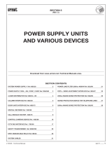
Fig.1. The view of the module.
No.
[Fig.1]
Description
1
Connector.
12V The module’s power supply, DC voltage
GND Power supply mass
S- Control input, reacts on the connected ground, its operation is dependent on the selected
program
S+ Control input, reacts on adding the „+”, its operation is dependent on the selected program
R- The input resetting the relay, reacts on the connected ground
2 TIME/MODE 10-position ON / OFF switch, change of the parameters during programming
3
LED (green): time configuration indication (T1/T2):
hh - tens of hours (10-90 h)
h - hours (0-9h)
mm - tens of minutes (10-50 min)
m - minutes (0-9min)
ss - tens of seconds (10-50s)
s - seconds (0-9s)
4 SET/RST The button for changing the status of the relay or parameter selection during programming
5 PROGRAM programming mode jumper
6 Red PROG LED - confirmation in programming mode
7 Red REL LED - indication of relay status (ON = active)
8 Relay
9 Relay connector.
NO Opened contact of the output relay
C Common contact of the relay
NC Shorted contact of the output relay

2
Description of jumpers and switches.
PROGRAM jumper – when the jumper is on during the module operation, it starts the operating
mode selection and programming times.
SET/RST button – enables / disables the REL relay during normal operation; when
programming, it approves the selected parameter and proceeds to edit the next one.
TIME/MODE switch - in the programming mode it allows selecting the operation mode and setting
the time.
CAUTION! Only one switch can be in ON position at the same time, no switch in ON position or the no.
10 switch in ON position are recognized as 0.
Optical indication.
Normal operation:
The S LED flashes with 0.5 Hz frequency indicating correct operation of the module and the timer; in
programming mode, it indicates the entered seconds digits.
The REL LED indicates the REL relay activation.
Programming mode:
hh, h, mm, m, ss, s LEDs indicate the time configuration (T1/T2).
The number of flashes of the PROG LED indicates the value of the selected time unit or other
parameter.
Table 2. Specifications.
3. Relay programs – operation modes.
Description of signals on the timing diagrams.
U – supply voltage
S – activation signal, control signal (S- or S+ clamp)
R – resetting signal (R- clamp)
REL – the actuation relay status
Fig. 2. The scheme of connecting the PC1 module (example).
Supply voltage 10 V÷ 14 V DC
Power consumption 9 mA/51 mA (inactive/active relay) (-5%/+5%)
S+ input 10,0/14,0V control (±5%)
S- input 0V (GND) control
R- input 0V (GND) control
Time range 1s ÷ 99h:59min:59s (stored in EEPROM memory )
The number of relays 1
Maximum connection voltage 50V AC /24V DC
Maximum connection current 7 A
Relay’s contacts NO/C/NC
Maximum contact resistance <100 mOhm
Optical indication of operation LED light: programming mode, relay status
Operation parameters
I environmental class, 5°C - 40°C, relative humidity Rh=75%max. No
condensation.
Printed Circuit Board
dimensions
100 x 43 x 23 (WxLxH)
Mounting
mounting tape or dowel pins x2 (holes3mm)
Connectors Ф0,41÷1,63 (AWG 26-14)
Net/gross weight 0,045 /0,085 [kg]

3
T
U
T1T1
S
R
REL
Tryb monostabilny
T
U
S
R
REL
Tryb bistabilny
T
U
S
R
REL
Tryb zatrzask
T
U
S
R
REL
T1 T1
Tryb opóźnione zadziałanie
2. Bistable mode:
Adding the S signal activates the REL;
the next S control signal turns off the
REL. Adding the R signal disables the
REL.
4. Delayed actuation:
Adding the S signal starts the T1
countdown; once the countdown is finished,
the REL is activated until disabled by the R
signal. The R signal does not affect the
countdown time - disabling is only possible
after the countdown. If the R signal was on
during/before the countdown, disabling is
only possible when the R signal is
disconnected and reconnected to the
module's input.
3. Latch mode:
Adding the S signal activates the REL, the
next S signal does not cause a reaction,
adding the R signal disables the REL.
1. Monostable mode:
Adding the S control signal is followed by
switching the REL for the T1 time. Once
the set time has elapsed, the REL is
turned off; during the countdown, the S
signal does not extend the time of the
REL activation; adding the R signal
resets the REL.
Monostable mod
Bistable mode
Latch mode
Delayed actuation

4
T
U
S
R
REL
T1
T1
Tryb opóźnione wyłączanie
T
U
S
R
REL
T1
T1 T1
Tryb odwołanie wyłączenia
T
U
S
R
REL
T1
T2
T1
Regulowane opóźnienie zadziałania z
regulowanym czasem załączenia REL
T
U
S
R
T1 T2
T1+Ts
Ts
T2
T2
Praca cykliczna z regulacją czasów
wyłączenia T1 i załączenia T2
5.
D
elayed
shutdown
mode
:
Adding the S signal activates the REL
immediately; once the S signal
disappears, the T1 countdown is started;
once the countdown is finished, the REL
relay is turned off.
7.
Adjustable delay time
and
REL
activation:
Adding the S signal starts the T1
countdown; once the countdown is
finished and the S is still active, the REL
is activated for the T1 time. Adding the R
disables the REL and starts waiting to
receive the S signal again.
.
8.
Cyclic operation with adjustable
turn
off T1 and turn on T2 time:
With the power on, the REL relay is active
for the T1 time; next, the T2 break
countdown is started, once the countdown
is finished, the T1 is activated again. The
break/activation countdown can be stopped
by adding the S signal (level control).
Adding the R disables the REL and starts
the countdown again.
6.
Disabling the
shutdown
:
With the power on, the REL relay is
active for the T1 time; if a signal is added
to the S input, the REL remains active, if
a signal is not added, the REL will be
disconnected. Adding the R disables the
REL.
Delayed shutdown mode
Disabling the shutdown
Adjustable delay time and REL activation
Cyclic operation with adjustable
turn off
T1 and turn on T2 time

5
4. Programming the parameters.
1. Set the PROGRAM jumper, which will be confirmed with 10 short flashes of the PROG diode.
2. Selection of the relay program: select the required program (1-8) by switching ON the corresponding TIME
/ MODE dip switch. The number of selected program will be indicated by blinking of the PROG diode.
3. Press the SET/RESET button, the diode will confirm the selected program with fast flashes. Depending on
the selected program, the module switches to T1 or T2 time configuration or the programming will be finished
(programs no. 2 and 3).
4. Setting the T1/T2 activation time:
a) the hh diode flashes, entering tens of hours, the PROG LED indicates the selected value
b) press the SET/RESET button
c) the h diode turns on, entering hours digits, the PROG diode indicates the selected value
d) press the SET/RESET button
e) the mm diode flashes, entering tens of minutes, the PROG diode indicates the selected value
f) press the SET/RESET button
g) the m diode flashes, entering minutes digits, the PROG diode indicates the selected value
h) Press the SET/RESET button
i) the ss diode flashes, entering tens of seconds, the PROG diode indicates the selected value
j) Press the SET/RESET button
k) the s diode flashes, entering seconds digits, the PROG diode indicates the selected value
5. Setting the time of the T2 activation. The procedure is the same as in the section 4.
6. Programming completion is indicated with 10 short flashes of the PROG diode.
7. Remove the PROGRAM jumper.
Caution. The relay stores the program and time settings after disconnecting.

6
4.1 Examples of programming
Example no. 1.
Programming in „latch mode”– program number 3.
1. Turn the power on
- The green S LED should be blinking (about once every two seconds)
2. Set the PROGRAM jumper.
- The S LED turns off and the red PROG LED flashes a few times to confirm the start of the
programming.
3. Select the appropriate program, in this case - No. 3. Set the switch no. 3 ON (the other in the
OFF position).
- The PROG LED should start blinking according to the sequence: 3 blinks - pause,
indicating the value set on the switch. If the LED is not flashing, it may indicate that more than one
switch is in the ON position.
4. Confirm your selection by pressing the SET/RESET button
- The PROG LED will blink several times to indicate saving of the selected program. Next, the
S LED will start blinking at a frequency of 0.5 Hz - the module is ready for operation.
5. Remove the PROGRAM jumper
Example no. 2.
Programming in ,, delayed shutdown mode“– program number 5. Delay time - 1min. 5 sec.
1. Turn the power ON
- The green S LED should be blinking (approximately once every two seconds)
2. Set the PROGRAM jumper
- The S LED turns off and the red PROG LED flashes a few times to confirm the start of the
programming (if the jumper was ON before switching on the power supply, it is necessary to remove
it and set once again, without disconnecting the power).
3. Select the appropriate program, in this case - No. 5. Set the switch no. 5 ON.
- The PROG LED should start blinking according to the sequence: 5 blinks - pause,
indicating the value set on the switch. If the LED is not flashing, it may indicate that more than one
switch is in the ON position
4. Confirm your selection by pressing the SET/RESET button
- The PROG LED will blink several times to indicate saving of the selected program. Next,
the LED HH (tens of hours) will turn on.
5. Setting the turn-off delay time:
a) In this case the set time is: 00h 01m 05s. Enter a “0” in the “tens of hours” field
b) Switch the Timer/Mode switch no. 5 OFF - the PROG LED stops flashing, signaling the “0” set.
Press the SET/RESET button – the LED H (hours digits) turns on. Press the SET/RESET button
again two times to proceed to minutes digits.
c) Set the Timer/Mode switch no. 1 ON to enter the minutes digits. The LED PROG starts flashing.
d) Press the SET/RESET button: Once the settings are saved, the SS LED will light up.
Set the Timer/Mode switch no. 1 OFF and press the TIME/MODE button. The ,,0’’ is saved , the S
LED (seconds digits) turns on.
e) Set the Timer/Mode switch no. 5 ON and press the SET/RESET button.
The PROG LED flashes a few times, then the S LED flashes signaling the correct operation of the
module.
6. Remove the PROGRAM jumper
Factory settings:
- - monostable mode of operation (program 1).
- - relay hold time T1=5s.
Pu
lsar K.Bogusz Sp.j.
Siedlec 150, 32-744 Łapczyca, Poland
Phone (+48) 14-610-19-40, Fax (+48) 14-610-19-50
E-mail: biuro@pulsar.pl, sales@pulsar.pl
http:// www.pulsar.pl, www.zasilacze.pl
WARRANTY
Pulsar K. Bogusz Sp.j. (the manufacturer) grants a two-year
warranty for the equipment, counted from the device’s production
date.
WEEE
LABEL
According to the European Union WEEE Directive, waste electrical and electronic equipment should be disposed of separately from
normal household waste. Waste electrical and electronic equipment must not be disposed of with normal household waste.
/