Page is loading ...

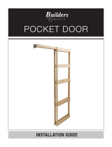
9850HD SDH Pocket Door Kit
Installation Instructions
I-SD00432
Rev 1, Rev Date: 02/04/21
Always visit www.hagerco.com for the latest Installation Instructions
HAGER COMPANIES 139 Victor Street, St. Louis, MO 63104 • (800) 325-9995
Page 1 of 6
1 Prepare the Rough Opening
Opening Dimensions from Door Heights (Table 1)
Part Number
Door Height (H)
Rough Opening Height
from Finished Floor
Bracket Fastener Height
from Finished Floor
9850HD-96
8’-0” Door
100-1/2”
96-3/4”
9850HD-102
8’-6” Door
106-1/2”
102-3/4”
Custom
H + 4-1/2”
H + 3/4”
Opening Dimensions from Door Widths (Table 2)
Door Width (W)
Rough Opening Width
Header Length
Nailing Board Length
4’-0”
97”
96-5/8”
48-7/8”
3’-10”
93”
92-5/8”
46-7/8”
3’-8”
89”
88-5/8”
44-7/8”
3’-6”
85”
84-5/8”
42-7/8”
3’-4”
81”
80-5/8”
40-7/8”
3’-2”
77”
76-5/8”
38-7/8”
3’-0”
73”
72-5/8”
36-7/8”
Custom
(2 x W) + 1”
(2 x W) + 5/8”
W + 7/8”
Contents:
Qty:
1. Header and Track Assembly
2. Pocket End Bracket
3. Doorway End Bracket
4. Floor Plates (For 1-3/8” Thick Doors)
5. Split Stud
6. 250lb 4-wheel Roller for 9850HD
7. Hanger Plate
8. Floor Guide (9883CS)
9. Rubber Bumper (9881CS)
10. M5.5 x 32mm PPHW Hanger Plate Screw
11. M4.2 x 13mm Washer PHW Floor Guide Screw
12. #8 x 5/8” PPHW Bumper Screw
13. #8 x 5/8” PPHW End Bracket Screw
14. Nails
15. Hanger Wrench
16. Adapter Kit For 1-3/4” Thick Doors
1
1
1
3
6
2
2
2
1
4
2
1
2
18
1
1
3.
2.
7.
5.
1.
9.
8.
14.
15.
6.
12.
11.
10.
4.
13.

9850HD SDH Pocket Door Kit
Installation Instructions
I-SD00432
Rev 1, Rev Date: 02/04/21
Always visit www.hagerco.com for the latest Installation Instructions
HAGER COMPANIES 139 Victor Street, St. Louis, MO 63104 • (800) 325-9995
Page 2 of 6
• Measure the rough opening using Table 1 and 2 or Figure 1
• Plumb the rough studs and ensure the floor is level
Figure 1
Figure 2
2 Mount the Header Brackets
• Using Table 1 or Figure 2, mark the bracket fastener height on each side of the rough opening.
Note: If measuring from a rough sub-floor, make sure to add the estimated thickness of the finished floor
material and/or carpeting.
• Drive a fastener (not included) on the centerline of each rough stud at the height marked on the previous step.
Leave 1/8” (3.17 mm) of the fastener protruding.
Note: Fastener used is based on the material of the rough studs
• Slide each end bracket’s slot in the fastener heads. Make sure to use the pocket end bracket for the pocket side
rough stud and doorway end bracket for the doorway side rough stud. See Figure 6.
• Level the brackets
• Drive the fastener all the way in
• Drive additional fasteners to secure the brackets
3 Mount the Frame Hardware
• Prepare the header and track assembly
Note: The header and track assembly on each kit will fit a 4’-0” (121.92 cm) door. However, the header and
track assembly can easily be cut to accommodate shorter size door as shown below using the dimensions from
Table 2.
a. Cut the wood header to the
desired length (Table 2)
Figure 3
b. Turn the header on its side to cut
the nailing boards to the desired
length. Make sure not to cut the
track or the wood header. (Table 2)
Figure 4
c. Turn the header and track assembly
back over and cut the track 1-1/4”
(31.75 mm) from the pocket end of
wood header. Make sure to cut the
track only.
Figure 5

9850HD SDH Pocket Door Kit
Installation Instructions
I-SD00432
Rev 1, Rev Date: 02/04/21
Always visit www.hagerco.com for the latest Installation Instructions
HAGER COMPANIES 139 Victor Street, St. Louis, MO 63104 • (800) 325-9995
Page 3 of 6
• Draw two reference chalk lines on the floor that
are even with the sides of the rough studs
• Insert both 4-wheel rollers into the track before
installing the header and track assembly
• Screw the header and track assembly to the
attached end brackets with the #8 x 5/8” Pan
Phillips Head Wood Screws. Make sure the
pocket end bracket is the one attached to the
pocket end of the header and track assembly.
See Figure 6.
Note: 9850HD pocket door kits can be used for
both 1-3/8” and 1-3/4” thick doors. Use the
included Adapter Kit for 1-3/4” thick doors. This
kit has wider floor plates and shims that may be
inserted between the header and track assembly
and the split studs.
Figure 6
4 Install the Split Studs
• Insert the floor plates into the bottom of the split studs
Note: The bottom of the split stud is the end without the slots as seen in Figure 7. If the split studs must be cut
for shorter doors, determine which end of the split stud has the slots and cut off the other end.
Figure 7
Figure 8

9850HD SDH Pocket Door Kit
Installation Instructions
I-SD00432
Rev 1, Rev Date: 02/04/21
Always visit www.hagerco.com for the latest Installation Instructions
HAGER COMPANIES 139 Victor Street, St. Louis, MO 63104 • (800) 325-9995
Page 4 of 6
• Butt one pair of the split studs against the header nailing boards with the slots side against the header as seen in
Figure 7
• Nail the split studs to the header while making sure the nails are driven through the center of the slots
• Nail the other two pairs of split studs to the header. Make sure each pair of split studs are equally spaced from
the other pairs of split studs, as seen in Figure 8
Note: Nails to secure the split studs to the header are included
• Position the floor plates between the chalk lines and plumb the split studs to make sure they are vertical and
square
• Secure the floor plates using the appropriate fasteners (not included) for the material of the floor
5 Mount the Door Hardware
• Seal all 6 sides of the door
• Create a pilot hole using a 5/64” drill bit at the center of the pocket side door thickness, 40” from the bottom of
the door. See Figure 9.
• Install the bumper using the #8 x 5/8” Pan Phillips Head Wood Screws
• Position both hanger plates center of the top door edge thickness. One 2-1/4” from the left door edge and the
other 2-1/4” from the right door edge. Make sure the slots on both hanger plates are facing the pocket side
door edge. See Figure 10
• Create pilot holes using a 7/64” drill bit and the hanger plates as templates
• Install the hanger plates using the M5.5 x 32mm Pan Phillips Head Wood Screws
Figure 9
Figure 10

9850HD SDH Pocket Door Kit
Installation Instructions
I-SD00432
Rev 1, Rev Date: 02/04/21
Always visit www.hagerco.com for the latest Installation Instructions
HAGER COMPANIES 139 Victor Street, St. Louis, MO 63104 • (800) 325-9995
Page 5 of 6
6 Hang the Door
• Unlatch the hanger plates
• Slide the hanger plates’ slot onto the 4-wheel
rollers’ bolt
• Latch the hanger plates
Figure 11
7 Finish the Jambs and Trim
• Apply wall material
Note: Make sure the fastener used to apply the
wall material is no longer than necessary to
avoid scratching or damaging the door when
opening or closing the pocket door
• Install the finish solid and split jambs by butting
them all the way up against the top and bottom
corners of the opening. Make sure the finish
solid and split jambs are level. Use shims, as
necessary.
Note: Leave 1/8” minimum clearance between
the finish split jamb edges and the door. See
Figure 16.
Figure 12
• Use the hanger wrench provided to adjust the
door hangers. Make sure to square the door to
the finish solid jamb.
Note: There is about half an inch of adjustment
that can be made with the door hangers
Figure 13

9850HD SDH Pocket Door Kit
Installation Instructions
I-SD00432
Rev 1, Rev Date: 02/04/21
Always visit www.hagerco.com for the latest Installation Instructions
HAGER COMPANIES 139 Victor Street, St. Louis, MO 63104 • (800) 325-9995
Page 6 of 6
Figure 14
• Install the finish split header by butting them all the
way up against the finish solid and split jamb. Make
sure the finish split header is level. Use shims, as
necessary.
Note: To allow for future door adjustments or removal,
at least one finished split header should be attached
with screws only. The one on your right hand
overhead as you face the door in the pocket is
recommended.
Figure 15
• Install the finish trim or casing.
Note: Make sure to fasten the finish header trim to
ONLY the wall and NOT the finish split header. This
ensures the finish split header can be removed later
without damage.
Figure 16
• Create pilot holes to the finish split jamb using a 5/64”
drill bit and the Floor Guide as templates. See Figure
16.
• Install the Floor Guide using the M4.2 x 13mm Washer
Phillips Head Wood Screw
/


