1. DESCRIPTION
The BA317E-SS is an intrinsically safe, one input Tachometer
housed in a rugged 316 stainless steel panel mounting enclosure,
which can operate with a wide range of sensors.
This abbreviated instruction sheet is intended to assist with
installation, a comprehensive instruction manual describing safety
certication, system design and conguration may be downloaded
from the BEKA website or may be requested from the BEKA sales
oce.
The BA317E-SS has IECEx, ATEX and UKEX intrinsic safety
certication for use in ammable gas and dust atmospheres. ETL
and cETL approval permits installation in the USA and Canada.
The certication information label, which is located on the top of
the instrument enclosure, shows the certication numbers and
codes. Other certications may be shown. Copies of certicates
may be downloaded from the BEKA website.
Typical certication information label
Other approvals may be shown
Special conditions for safe use
The IECEx, ATEX and UKEX intrinsic safety certicate numbers
have an ‘X’ sux indicating that for some applications special
conditions apply for safe use.
a. When installed in an Ex e, Ex p or Ex t panel enclosure
all connections to the BA317E-SS must be made by
appropriately rated Zener barriers or galvanic isolators.
This means that when installed in an Ex e, Ex p or Ex t panel
enclosure the BA317E-SS remains an intrinsically safe instrument.
b. The front of the stainless steel enclosure complies with the
requirements for Ex e, Ex p & Ex t type of protection.
Therefore when correctly installed the BA317E-SS Tachometer will
not invalidate the Ex e, Ex p or Ex t panel enclosure certication.
Use in combustible dust atmospheres
See full instruction manual for installation information
requirements and special conditions for safe use in combustible
dust atmospheres.
2. INSTALLATION
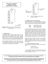
Cut-out dimensions
Mandatory to achieve an IP66 seal between instrument and
panel and to maintain certication of panel enclosure in which it
is mounted.
105
8013
60
DISPLAY
Captive gasket
Maximum
panel thickness
8 mm
+
A1 A2 A3 A4 P1 P2
+
Alarm 1 Alarm 2
Terminals for
optional dual alarms
Terminals for
optional pulse
output
Terminals
for optional
4/20mA output
+
C1 C2 C3 C4
OR OR
Reset Add link
to energise
pulse
input
Pulse
input
Power
supply
10 to 28V dc
RS1 RS2
3 4
+
5 6
1 2
+
Connect M4 earth
stud to panel
enclosure in which
instrument is mounted
E
+
Panel cut-out 90 +0.5 / -0.0 x 43.5 +0.5 / -0.0
Typical
terminals shown
Support panel wiring to prevent vibration damage
Fig 1 Cut-out dimensions and terminals
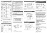
Slide a panel clamp into the
two grooves at each corner
of the instrument
Secure each clamp
with a stainless steel washer and wing nut,
tighten 22cNm (1.95lbf in) min. Finally fit protective caps.
Optional
stainless steel
support plate
Captive gasket
Panel
enclosure
Fig 2 Installation procedure
EMC
For specied immunity all wiring should be in screened twisted
pairs with screens earthed at one point within the safe area.
Single channel positive polarity
28V: 93mA Zener Barrier
Single channel positive polarity
28V: 93mA Zener Barrier
Remote reset
in safe area
2 16 5
++
4 3
+
RS2
RS1
Voltage pulse
Magnetic pick-off
Proximity detector
Switch contact/
open collector
OR
N
S
Power
supply
External
run-time
reset
6 5
No
link
4 3
Safe areaHazardous area
+
++
DISPLAY
Fig 3 Use with Zener barriers
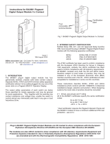
Scale card
The Tachometer’s units of measurement are shown on a printed
scale card visible through a window at the right hand side of
the display. The scale card is mounted on a exible strip that is
inserted into a slot at the rear of the instrument as shown below
I
n
s
e
r
t
Unlock
Lock
Fig 4 Inserting exible strip carrying scale
card into slot at the rear of Tachometer.
Thus the scale card can easily be changed without removing the
Tachometer from the panel or opening the instrument enclosure.
New Tachometers are supplied with a printed scale card showing
the requested units of measurement, if this information is not
supplied when the instrument is ordered a blank card will be tted.
A pack of self-adhesive scale cards printed with common units of
measurement is available as an accessory from BEKA associates.
Custom printed scale cards can also be supplied.
To change a scale card, unclip the protruding end of the exible
strip by gently pushing it upwards and pulling it out of the enclosure.
Peel the existing scale card from the exible strip and replace it with
a new printed card, which should be aligned as shown below. Do
not t a new scale card on top of an existing card.
Align the self-adhesive printed scale
card onto the exible strip and insert
the strip into the Tachometer as
shown.
Fig 5 Fitting scale card to exible strip
3. OPERATION
The Tachometer is controlled by four front panel push buttons.
When in the operating mode they have the following functions:
( + ) Access to conguration menu.
& + * If the Local Run-time reset function CLr tot in the
instrument conguration menu is enabled, operating
the & and * buttons simultaneously for more than 3
seconds resets the run-time display to zero.
) + * Run-time grand total.
If buttons are pressed for ten seconds or longer grand
total run-time is reset to zero. This is a congurable
function.
( + & Shows in succession, rmware version number,
instrument function tacho and any output accessories
that are tted:
- A Dual Alarm Outputs
- P Pulse output
- C 4/20mA output.
( + * When optional alarms are tted provides direct access
to the alarm setpoints if A5CP (access to setpoints) has
been enabled in the conguration menu.
Abbreviated instructions for
BA317E-SS Rugged one input
intrinsically safe Tachometer
Issue 4
24th November 2022
BEKA associates Ltd. Old Charlton Rd, Hitchin, Hertfordshire,
web: www.beka.co.uk
BA317E-SS
Align on
these
edges
Scale
card