Page is loading ...

T10 & T10+ Pro Smart
Thermostat with RedLINK® 3.0
Product Data
74
2
18%
M37811A
33-00462-05


1 33-00462—05
CONTENTS
Application .............................................................................................................................................................................. 1
Features ................................................................................................................................................................................... 1
Apple® HomeKit™ Setup Code ................................................................................................................................................ 1
Specifications ......................................................................................................................................................................... 2
Model Numbers ........................................................................................................................................................................ 4
Dimensions ............................................................................................................................................................................... 5
System Installation ................................................................................................................................................................. 7
When Installing This Product .................................................................................................................................................... 7
Finding Your Password (Date Code) ........................................................................................................................................ 7
Selecting Thermostat Location ................................................................................................................................................. 7
UWP Mounting System Installation ........................................................................................................................................... 7
Optional Decorative Cover Plate Installation ............................................................................................................................ 7
Wiring UWP .............................................................................................................................................................................. 8
Setting Slider Tabs ................................................................................................................................................................... 9
Wiring ....................................................................................................................................................................................... 10
Wiring at T10 or T10+ Without EIM .......................................................................................................................................... 10
Whole house humidifier, dehumidifier, or ventilator wiring ........................................................................................................ 14
Installing Equipment Interface Module (if used) .................................................................................................................. 16
EIM Wiring Diagrams ................................................................................................................................................................ 16
Wiring Dry Contact Alerts with EIM ........................................................................................................................................... 22
Linking the T10+ to an Optional EIM ........................................................................................................................................ 23
To Replace the Equipment Interface Module (EIM) .................................................................................................................. 24
To replace a T10+ connected to an EIM ................................................................................................................................... 24
Sensor Installation .................................................................................................................................................................. 25
Wireless Indoor Sensor Installation .......................................................................................................................................... 25
Wireless Outdoor Sensor Installation ........................................................................................................................................ 25
Selecting Return Air Temperature Sensor Mounting Location .................................................................................................. 27
Selecting Discharge Air Temperature Sensor Mounting Location ............................................................................................ 27
Installing Discharge and/or Return Air Temperature Sensors
(T10+ only) ................................................................................................................................................................................ 28
Installing Wired Indoor Sensor .................................................................................................................................................. 28
Installing Wired Outdoor Sensor ............................................................................................................................................... 29
Floor/Slab Sensor (T10+ only) .................................................................................................................................................. 30
Installer Setup ......................................................................................................................................................................... 32
New Installation ........................................................................................................................................................................ 32
Revising Settings ...................................................................................................................................................................... 32
WiFi Setup ............................................................................................................................................................................... 43
Connect to a Hidden WiFi Network ........................................................................................................................................... 43
Unsuccessful WiFi Connection ................................................................................................................................................. 43
Scheduling .............................................................................................................................................................................. 44
Setting a Schedule On Thermostat ........................................................................................................................................... 44
Scheduling Through the App .................................................................................................................................................... 45
Schedule Override on Device ................................................................................................................................................... 46
Main Menu ............................................................................................................................................................................... 47
Main Menu Options ................................................................................................................................................................... 47
Management ............................................................................................................................................................................. 48
Installer Options ..................................................................................................................................................................... 50

33-00462—05 2
Getting the Most From the T10 or T10+ Smart Thermostat .................................................................................................51
Apple® HomeKit ™ Setup ........................................................................................................................................................51
Using Your Thermostat .............................................................................................................................................................52
Setting the Time/Date ...............................................................................................................................................................52
Setting the Fan ..........................................................................................................................................................................52
Setting the System Mode ..........................................................................................................................................................52
Using Priority .............................................................................................................................................................................53
Selecting Sensors .....................................................................................................................................................................53
Priority Screen .......................................................................................................................................................................... 53
Alerts and Notifications .............................................................................................................................................................53
IAQ Reminders .........................................................................................................................................................................53
Setting Preferences .................................................................................................................................................................. 54
Fallback Room (T10+ only) .......................................................................................................................................................54
Indoor Air Quality Control ......................................................................................................................................................55
Humidification ...........................................................................................................................................................................55
Dehumidification ....................................................................................................................................................................... 55
Ventilation ................................................................................................................................................................................. 57
Advanced Features .................................................................................................................................................................58
Cleaning the Thermostat Screen ..............................................................................................................................................58
Adjusting Security Settings ....................................................................................................................................................... 58
Dealer Information ....................................................................................................................................................................58
Auto Changeover Operation .....................................................................................................................................................59
Em Heat and Auxiliary Heat Operation .....................................................................................................................................59
Adaptive Intelligent Recovery ...................................................................................................................................................59
Compressor Protection .............................................................................................................................................................60
P + I Control .............................................................................................................................................................................. 60
Heat Differential ........................................................................................................................................................................ 60
Holdoff Timer ............................................................................................................................................................................ 61
Programmed Recovery .............................................................................................................................................................61
Finish with High Heat stage and/or Finish with High Cool stage ..............................................................................................61
Heat Pump and Backup Heat Lockout Operation ..................................................................................................................62
Dry Contact Alerts (ISU 6000- 6220) ........................................................................................................................................63
Battery Replacement ................................................................................................................................................................ 64
Resideo Pro App .....................................................................................................................................................................65
Frequently Asked Questions (FAQs) ..................................................................................................................................... 66
WiFi connection questions ........................................................................................................................................................66
Resideo account and app questions .........................................................................................................................................66
Software and security questions ...............................................................................................................................................66
Other questions .........................................................................................................................................................................66
Troubleshooting ......................................................................................................................................................................68
Regulatory information ..........................................................................................................................................................71

1 33-00462—05
Fig. 1.
APPLICATION
The T10 and T10+ Smart Thermostats feature effortless, 7-
Day programming on an easy-to-use touchscreen.
Compatible with 24 VAC systems including:
• Up to 3 Heat/2 Cool heat pump systems (4 heat with
T10+ & EIM)
• Up to 2 Heat/2 Cool conventional (3 Heat/2 Cool with
T10+ & EIM)
• Dual Fuel systems
• Radiant hot water systems including hot water fan coil
• Humidification, dehumidification, or ventilation (All three
with T10+ & EIM)
FEATURES
• RedLINK 3.0 C7189R3002 or C7189R2002 Indoor
Sensor Compatible (Up to 20 sensors per thermostat).
• Increase your content and profit per job by including
RedLINK 3.0 indoor temperature, humidity, and motion
sensors that meet your customers’ comfort and
convenience needs. They can be used in combination
for temperature averaging or individually. These devices
also sense motion and you can select priority zones
based on where motion is detected or by scheduling.
• Flexible scheduling: You can choose to use location-
based temperature control (Geofence technology),
program a set schedule or use a combination of both to
make sure your home is always comfortable.
• Location-based temperature control: Using geofence
technology, the T10 or T10+ Smart Thermostat will
automatically use your smartphone’s location, which can
save energy when you leave and make your home
comfortable by the time you return. See “Scheduling” on
page 44 for more.
• Smart scheduling: Adds a Sleep period to location-
based temperature control. See “Scheduling” on
page 44 for more.
• Time-based scheduling: You can program a schedule in
which every day is different, a schedule where
weekdays and weekends are different or a schedule
where every day is the same. There are four adjustable
periods per day: Wake, Away, Home and Sleep. See
“Scheduling” on page 44 for more.
• No schedule: You can also choose to disable schedule
and adjust the thermostat manually. See page 47.
• Tip: The Resideo app can be used to manage multiple
thermostats and multiple users in a household.
• Smart Alerts: T10 or T10+ Smart Thermostat can send
alerts for occurrences such as extreme indoor
temperatures and reminders for filter changes and other
required maintenance.
• Auto change from heat to cool: When Auto mode is
selected, the T10 or T10+ Smart Thermostat can
automatically determine whether your home needs
heating or cooling to reach the desired temperature.
• Adaptive Intelligent Recovery: T10 or T10+ Smart
Thermostat learns your heating and cooling cycle times
to make sure the system delivers the temperature you
want, when you want it.
Apple® HomeKit™ Setup Code
The T10 or T10+ Smart Thermostat supports HomeKit. At
thermostat, select the menu icon at bottom of screen. Then
choose HomeKit setup from the options and follow the
instructions (see page 51).
74
2
18%
M37811A

33-00462—05 2
SPECIFICATIONS
*4H/2C heat pump or 3H/2C conventional with T10+ & EIM
** T10+ with EIM can control three IAQ devices.
Power Consumption: 3VA
Table 1. T10 & T10+ Thermostat Description.
Feature Description
Powering Method Common wire required
Stages:
•Up to 3H/2C*
Heat pump
•Up to 2H/2C*
conventional
•Radiant floor with
slab sensor
(T10+ only)
Equipment type:
•Dual fuel
•Hot water, steam, or hot water coil
•Gas or oil furnace
•High-efficiency or mid-efficiency
•Cool only
•Humidifier, Dehumidifier, or
Ventilator control**
Changeover Manual or Auto Changeover Selectable
System Setting Em Heat-Heat-Off-Cool-Auto
Fan Setting Auto-On-Circ-Follow Schedule
Table 2. Electrical ratings of T10 or T10+ Without EIM.
Terminal
Voltage
(50/60Hz)
Running
Current
W (Heat) 20-30 VAC 0.02-1.0 A
W2 (Aux) Heat 20-30 VAC 0.02-1.0 A
E (Emergency Heat) 20-30 VAC 0.02-0.5 A
Y (Compressor Stage 1) 20-30 VAC 0.02-1.0 A
Y2 (Compressor Stage 2) 20-30 VAC 0.02-1.0 A
G (Fan) 20-30 VAC 0.02-0.5 A
O/B (Changeover) 20-30 VAC 0.02-0.5 A
L/A (Heat Pump Fault) 20-30 VAC 0.02-0.5 A
U (Hum, Dehum, or Vent) 20-30 VAC 0.02-0.5 A
Table 3. Electrical ratings of EIM (for use with
T10+ models).
Terminal
Voltage
(50/60Hz)
Max. Current
Rating
O/B 18-30 VAC 1.00 A
Y (Compressor Stage 1) 18-30 VAC 1.00 A
Y2 (Compressor Stage 2) 18-30 VAC 1.00 A
G (Fan) 18-30 VAC 0.50 A
W1 18-30 VAC 0.60 A
W2/Aux 1 (Heating) 18-30 VAC 0.60 A
W3/Aux 2 (Heating) 18-30 VAC 0.60 A
L (Input only) 18-30 VAC 0.60 A
U1, U1
U2, U2
U3, U3
18-30 VAC 0.50 A

3 33-00462—05
RedLINK Communication:
Frequency: 900 MHz frequency range
Re-Sync Time: RedLINK devices re-establish communication
within 6 minutes after AC power resumes.
Temperature Setting Range:
Heating: 40 to 90 °F (4.5 to 32 °C).
Cooling: 50 to 99 °F (10 to 37 °C).
Note: Adjustable high and low range-stop settings.
Humidification Setting Range:
0% to 90% RH.
Dehumidification Setting Range:
10% to 100% RH.
Humidity Display Range:
0% to 99%.
Humidity Sensor Accuracy:
± 5% RH from 30% to 50% RH at 75 F.
Cool Indication:
Display floods blue and says "Cooling to" when cool is on.
Heat or Em Heat Indication:
Display floods orange and says "Heating to" when heat is on.
AUX Heat Indication:
Display shows “Aux heat on” above the room temperature.
Interstage Differential:
Comfort (default setting):
The thermostat keeps the indoor temperature within 1
degree of the setpoint (droop less control). Unless the
system is dual fuel, or a droop setting is used, the
thermostat turns on stage 2 when the capacity on stage
1 reaches 90%.
See ISU 3030 for cool differential options.
See ISU 3050 and 3090 for backup heat differential
options.
Clock Accuracy:
1 minute per month at 77 °F (25 °C). ± 2 minutes per month
over the operating ambient temperature range.
Automatically updates when connected to WiFi router
and registered to account.
Mounting Means:
Thermostat mounts directly on the wall in the living space
using mounting screws and anchors provided. Can
mount to a horizontal 2 x 4 in. junction box using J-Box
adapter (included).

33-00462—05 4
Model Numbers
* For optimal Battery Life, operating temperature range of 35 to 114 °F (1.7 to 45.6 °C) is recommended.
* For optimal Battery Life, operating temperature range of 35 to 114 °F (1.7 to 45.6 °C) is recommended.
Table 4. T10 Thermostats and Accessories.
Product Part Number
Operating
Ambient
Temperature
Operating
Relative
Humidity
Shipping
Temperature
Dimensions in
inches (mm) Color
T10 thermostat THX321WF2003
W
T10 Thermostat
37 to 102 °F.
(2.8 to 38.9 °
5% to 90%
Non Condensing
-20 to 120 °F
28.9 to 48.9
°C)
T10 Thermostat
4.9" H x 3.7" W x
0.93" D
(125.4 H x 94.1 W x
23.68 D)
White
Kit with T10 thermostat with one
C7189R2002 sensor
THX321WFS200
1W
Wireless indoor temperature,
humidity, & motion sensor. Up to
20 per T10 thermostat (IAS)
(We are transitioning to
C7189R3002 sensors for all T10
models)
C7189R2002-2
(2 pack)
C7189R3002-2
(2-pack)
* 0 to 120 °F
(-17.8 to 48.9 °C)
5% to 90%
Non-Condensing
-20 to 120 °F
(-28.9 to 48.9
°C)
2.6" W x 2.6" H x .78" D
(66.25 W x 66.25 H x
19.7 D)
White
Table 5. T10+ and Accessories.
Product Part Number
Operating
Ambient
Temperature
Operating
Relative
Humidity
Shipping
Temperature
Dimensions in in.
(mm) Color
T10+ thermostat THX321WF3003W T10 +
37 to 102 °F.
(2.8 to 38.9 °C)
5% to 90%
Non-Condensing
-20 to 120 °F
(-28.9 to 48.9 °C)
T10+
4.9" H x 3.7" W x 0.93" D
(125.4mm H x 94.1mm W x
23.68mm D)
White
Kit with T10+ thermostat with one
C7189R3002 sensor
THX321WFS3001W
Kit with T10+ Thermostat, EIM, IAS,
RATS/DATS
YTHM1004R3000
Kit with T10+ Thermostat, EIM, IAS,
RATS/DATS, OAS
YTHM1004R3001
Wireless indoor temperature, humidity, &
motion sensor. Up to 20 per T10+
thermostat. (IAS)
C7189R3002-2
(2-pack)
*0 to 120 °F
(17.8 to 48.9 °C)
5% to 90%
Non-Condensing
-20 to 120 °F
(-28.9 to 48.9 °C)
2.6" W x 2.6" H x 0.78" D
(66.25 W x 66.25 H x
19.7 D)
White
Wireless outdoor temperature & humidity
sensor (OAS)
C7089R3013 -40 to 140 °F
(-40 to 60 °C)
0% to 90%
Non-Condensing
-40 to 140 °F
(-40 to 60 °C)
5" x 3-1/2" x 1-11/16"
(127 x 89 x 43)
Grey
Equipment Interface Module (EIM) THM04R3000 -40 to 165 °F
(-40 to 73.9 °C)
5% to 95%
Non-Condensing
-20 to 165 °F
(-28.9 to 73.9 °C)
4-53/64" W x
9-11/32" H x
1-19/32" D
(123 W x 237 H x 41 D)
Grey
Floor/Slab sensor for radiant floor heat
(T10+ only. 10K ohm)
AC112-01
Discharge or return sensor. (Two are
included with the T10+ & EIM kits)
C7735A1000
Table 6. Accessories for either T10 or T10+.
Product Part Number Dimensions in in. (mm)
Large Cover Plate & J Box Adapter Included with T10 & T10+ models other than
THX321WFS2001W
THP2400A1080 6.11" W x 6.11" H (155.3 X 155.3)
Large molded Cover Plate & J Box Adapter Included with THX321WFS2001W model of T10
& T10+ models
Cannot be ordered as a
separate accessory
5-1/2" W x 5-13/64" H (140 x 131)
Wired indoor temperature sensor (10K ohm) C7189U1005 1-1/2" W x 2-1/4" H x 3/4" D (38 W x 57 H x 19 D)
Wired outdoor temperature sensor (10K ohm) C7089U1006 2-1/4" W x 3/8" H with 60" lead wires
(57 x 10 with 1524 mm lead wires)
Wire saver module or C wire adapter (add a C wire). Various versions of this
made. Starts with
THP9045A

5 33-00462—05
Dimensions
Fig. 2. Dimensions of T10 & T10+ thermostat in inches (mm)
Fig. 3. Dimensions of C7189R2002 & C7189R3002 sensors
in inches (mm)
Fig. 4. Dimensions of THM04R3000 EIM in inches (mm)
Fig. 5. Dimensions of C7089R3013 wireless outdoor
sensor in inches (mm)
M37805
429/32
(125)
345/64 (94) 15/16
(24)
M39056
2-19/32 (66)
2-19/32
(66)
M33331A
4-53/64 (123)
8-7/8
(225)
9-11/32
(237)
1-19/32
(41)
M39054
3.5 (89)
5
(127)

33-00462—05 6
Fig. 6. Dimensions of J-Box adapter included with all T10
& T10+ models in inches (mm)
Fig. 7. Dimensions of molded grey cover plate included
with THX321WFS2001W in inches (mm)
Fig. 8. Dimensions of flat white cover plate included with
all T10 & 10+ models other than THX321WFS2001W in
inches (mm)
M37807
UP
329/32
(99)
329/32 (99)
M37808
513/64
(131)
51/2 (140) 13/32
(11)
11/16
(18)
9/32
(7)
67/64 (155)
67/64
(155)
M39055

7 33-00462—05
SYSTEM INSTALLATION
When Installing This Product...
1. Read these instructions carefully. Failure to follow the
instructions can damage the product or cause a
hazardous condition.
2. Check the ratings given in the instructions to make sure
the product is suitable for your application.
3. Installer must be a trained, experienced service
technician.
4. After completing installation, use these instructions to
verify the product operation.
Finding Your Password (Date Code)
You will need the thermostat password to:
• Add or remove RedLINK 3.0 accessories
• Make changes to Installer Setup
• Perform an Installer Test
• Reset Thermostat to Factory Default Settings
To find the password (date code) Press the menu (three
horizontal lines) Scroll down and select “Dealer Information”.
CAUTION
Electrical Hazard.
Can cause electrical shock or equipment
damage.
Disconnect power before wiring.
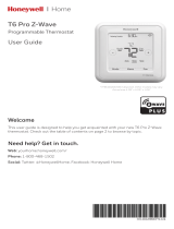
Selecting Thermostat Location
Install the thermostat about 5 ft. (1.5m) above the floor in an
area with good air circulation at average temperature. See
Fig. 9.
Fig. 9. Selecting thermostat location
Do not install the thermostat where it can be affected by:
— Drafts or dead spots behind doors and in corners
— Hot or cold air from ducts
— Radiant heat from sun or appliances
— Concealed pipes and chimneys
— Unheated (uncooled) areas such as an outside wall
behind the thermostat
UWP Mounting System Installation
1. Open package to find the UWP. See Step 1 in Fig. 10.
2. Position the UWP on the wall. Level and mark hole
positions. See Step 2 in Fig. 10.
Drill holes at marked positions, and then lightly tap
supplied wall anchors into wall using a hammer.
Drill 7/32” holes for drywall.
3. Pull the door open and insert wires through the wiring
hole of the UWP. See Step 3 in Fig. 10.
4. Place the UWP over the wall anchors. Insert and tighten
mounting screws supplied with the UWP. Do not over-
tighten. Tighten until the UWP no longer moves. Close
the door. See Step 4 in Fig. 10. Use 3x supplied screws
#8 1-1/2”.
Fig. 10.
Optional Decorative Cover Plate
Installation
Use the Optional Cover Plate when:
• Mounting the thermostat to an electrical junction box
• Or when you need to cover paint gap from the old
thermostat.
5. Separate the Junction Box Adapter from the Cover
Plate. See Step 5 in Fig. 11.
6. Mount the Junction Box Adapter to the wall or an electrical
box using any of the eight screw holes. Insert and tighten
mounting screws supplied with Cover Plate Kit. Do not
over-tighten. Make sure the Adapter Plate is level. See
Step 6 in Fig. 11. Use 2x supplied screws #6 5/8”.
7. Attach the UWP by hanging it on the top hook of the
Junction Box Adapter and then snapping the bottom of
the UWP in place. See Step 7 in Fig. 11.
8. Snap the Cover Plate onto the Junction Box Adapter.
See Step 8 in Fig. 11.
NOTE: Cover plate included with T10 or T10+ can vary by
model.
5 FEET
[1.5 METERS]
YES NO
NO
M37812
NO
1 2
3 4
1 2
3 4
12
34
M37786

33-00462—05 8
Fig. 11.
Wiring UWP
NOTE: If T10+ & EIM are used, UWP only wires to R and C
of a 24 VAC power supply. Usually R and C from
UWP goes to R & C at upper right of EIM.
Push down on the tabs to put the wires into the inner holes of
their corresponding terminals on the UWP (one wire per
terminal) until they are firmly in place.
Gently tug on the wires to verify they are secure.
If you need to release the wires again, push down the terminal
tabs on the sides of the UWP. This wiring is just an example,
yours may vary.
Fig. 12.
Terminal Designations
Table 7. Terminals on T10 or T10+ Without EIM
* The THP9045A C-wire adapter is used on heat/cool systems when you only have four wires at the thermostat and you need an
extra wire for a common wire. Use the K terminal in place of the Y and G terminals on conventional or heat pump systems to
provide control of the fan and the compressor through a single wire the unused wire then becomes your common wire. See
THP9045 instructions for more information.
** See note on Wiring U terminals on the following page.
Use 2x
supplied
screws
#6 5/8”
8
7
6
5
M37787
M37788
Conventional Systems Heat Pump Systems
Terminal Description Terminal Description
S/S Input for a wired sensor S/S Sensor options in charts on page 4
Y Compressor Stage 1 Y Compressor Stage 1
Y2 Compressor Stage 2 Y2 Compressor Stage 2
G Fan Relay G Fan Relay
C 24VAC Common wire from secondary side of
cooling transformer (if 2 transformers)
C 24VAC Common wire from secondary side of cooling
transformer
K* Connect to K on C-wire adapter K* Connect to K on C-wire adapter
U/U** Relay for humidifier, dehumidifier, or ventilator U/U** Relay for humidifier, dehumidifier, or ventilator
A L/A Connect to compressor monitor
W Heat Stage 1 O/B Changeover valve for heat pumps
W2 Heat Stage 2 AUX Backup Heat
E Emergency Heat
R 24 VAC Heating transformer R 24 VAC Heating transformer
Rc 24 VAC Cooling transformer Rc 24 VAC Cooling transformer

9 33-00462—05
Table 8. Terminals on THM04R3000 Equipment Interface Module (EIM) Used With T10+ Models Only.
Setting Slider Tabs
Set R Slider Tab, see Fig. 13.
• Use built-in jumper (R Slider Tab) to differentiate
between one or two transformer systems.
• If there is only one R wire, and it is connected to the
R, Rc, or RH terminal on the old thermostat, set the
slider to the up position (1 wire).
• If there is one wire connected to the R terminal and
one wire connected to the Rc terminal, set the slider
to the down position (2 wires).
Fig. 13.
Set U Slider Tab, see Fig. 14.
• Use built-in jumper (U Slider Tab) for IAQ device.
• When the U Slider Tab is in the down position (2
wires) the U contacts are a dry set of contacts.
• If your IAQ device is powered by the cooling
transformer, move the U Slider Tab to the up
position (1 wire). When this is done, the lower U
terminal is internally jumped to the Rc terminal. In
this application, you would hook up one wire from
your IAQ device to the upper U terminal and the
other to the common side of the cooling transformer.
The 1 wire setting is most commonly used when
using a fresh air damper for ventilation or using low
speed fan for dehumidification.
• See wiring examples on the next page.
Fig. 14.
Conventional Systems Heat Pump Systems
Terminal Description Terminal Description
S1, S2, S3, S4
(Two of each)
Input for indoor sensor, outdoor sensor, Floor sensor,
RATS, DATS, or Dry Contact Alert
S1, S2, S3, S4
(Two of each)
Input for indoor sensor, outdoor sensor, Floor sensor,
RATS, DATS, or Dry Contact Alert
Y Compressor Stage 1 Y Compressor Stage 1
Y2 Compressor Stage 2 Y2 Compressor Stage 2
G Fan Relay G Fan Relay
C
Common from HVAC transformer when R is jumped to Rc
.
Common from separate transformer if R is not
jumpered
C
Common from HVAC transformer when R is jumped to Rc
.
Common from separate transformer if R is not
jumpered
U1, U2, U3
(Two of each)
Relay for humidifier, dehumidifier, or ventilator U1, U2, U3
(Two of each)
Relay for humidifier, dehumidifier, or ventilator
L Not used for conventional applications L Connect to compressor monitor
O/B Not used for conventional applications O/B Changeover valve for heat pumps
W1 Heat Stage 1 W1 Not used for heat pump applications
W2 Heat Stage 2 AUX1 Stage 1 of AUX/EM heat
W3 Heat Stage 3 AUX2 Stage 2 of AUX/EM heat
R 24V from transformer to power EIM R 24V from transformer to power EIM
Rc 24 VAC Cooling transformer Rc 24 VAC Cooling transformer
Rh 24 VAC Heat transformer Rh 24 VAC Heat transformer
9
M37789
M37790

33-00462—05 10
WIRING
Wiring at T10 or T10+ Without EIM
NOTES:
1. Use 18- to 22- gauge thermostat wire. Shielded
cable is not required.
2. Set the R Slider Tab on the UWP to the up posi-
tion (1 wire) for 1 transformer systems or the
down position (2 wires) for 2 transformer systems.
3. Set the U Slider Tab to the position shown for IAQ
wiring diagrams on pages 14-15.
Wiring Diagrams for T10 or T10+ Without
EIM
Fig. 15. Heat only: Gas or oil furnace
Fig. 16. Cool only
Fig. 17. 1H/1C gas furnace
W R
G
C
S
S
Y
Y2
G
C
U
U
A
W2
W
K
Rc
R
L/A
E
AUX
M37813
1COMMON REQUIRED.
G USED FOR INDEPENDENT FAN CONTROL ONLY. MOST HEAT
ONLY, GAS OR OIL FORCED AIR SYSTEMS DO NOT USE A FAN
(G) WIRE.
2
12
FURNACE
R/Rc
SWITCH UP
O/B
HEAT ONLY.
GAS OR OIL FURNACE.
M37814
COOL ONLY.
1COMMON REQUIRED.
AIR-HANDLER
Y R
G
C
S
S
Y
Y2
G
C
U
U
A
W2
W
K
Rc
R
L/A
E
AUX
1
O/B
R/Rc
SWITCH UP
M37815
1H/1C GAS FURNACE +
AIR-CONDITIONING.
1COMMON REQUIRED.
W R
G
C
S
S
Y
Y2
G
C
U
U
A
W2
W
K
Rc
R
L/A
E
AUX
FURNACE
R/Rc
SWITCH UP
O/B
RW
Y
G
C
1
1

11 33-00462—05
Fig. 18. 2H/1C gas furnace
Fig. 19. 2-transformer system; 1H/1C oil furnace
Fig. 20. 2-transformer system; hot water heat with air-
conditioning (or hot water coil)
Fig. 21. Hot water heat with power open zone valve
M37816
2H/1C GAS FURNACE +
AIR-CONDITIONING.
1COMMON REQUIRED.
S
S
Y
Y2
G
C
U
U
A
W2
W
K
Rc
R
L/A
E
AUX
FURNACE
R/Rc
SWITCH UP
O/B
1
1
R
W
Y
G
CW2
M37556A
S
S
Y
Y2
G
C
U
U
A
W2
W
K
Rc
R
L/A
E
AUX
OIL FURNACE
R/Rc SWITCH
DOWN
O/B
RW
Y
G
CR
1COMMON REQUIRED FROM COOL TRANSFORMER (AIR HANDLER).
1
AIR HANDLER
2 TRANSFORMER SYSTEM
1H/1C OIL FURNACE +
AIR-CONDITIONING.
M37557A
S
S
Y
Y2
G
C
U
U
A
W2
W
K
Rc
R
L/A
E
AUX
BOILER
R/Rc SWITCH
DOWN
O/B
RW
Y
G
CR
1COMMON REQUIRED FROM COOL TRANSFORMER (AIR-HANDLER).
1
AIR HANDLER
2 TRANSFORMER SYSTEM
HOT WATER HEAT +
AIR-CONDITIONING (OR HOT
WATER COIL).
M37559B
S
S
Y
Y2
G
C
U
U
A
W2
W
K
Rc
R
L/A
E
AUX
BOILER
R/Rc SWITCH
UP
O/B
R (T)
W (T)
HOT WATER HEAT WITH
POWER OPEN ZONE VALVE.
1COMMON REQUIRED.
C
RESIDEO V8043
ZONE VALVES
1
TH
TR
TRANSFORMER
R
24 VOLTS
END SWITCH

33-00462—05 12
Fig. 22. Hot water boiler, heat only
Fig. 23. Series 20 valve (power open and power closed)
Fig. 24. 2H/2C: Gas furnace
Fig. 25. 1H/1C heat pump without aux heat
M37819
S
S
Y
Y2
G
C
U
U
A
W2
W
K
Rc
R
L/A
E
AUX
BOILER
R/Rc SWITCH
UP
O/B
R (T)W (T)
HOT WATER BOILER.
HEAT ONLY.
1COMMON REQUIRED.
1
1
C
M38997
S
S
Y
Y2
G
C
U
U
A
W2
W
K
Rc
R
L/A
E
AUX
R/Rc SWITCH
UP
O/B
COMPATIBLE MODELS:
TH4110U2005
TH4210U2002
1COMMON OPTIONAL TO THERMOSTAT.
THERMOSTAT MUST BE CONFIGURED FOR RADIANT HEAT
WITH 0 COOL STAGES.
C
POWER OPEN/
POWER CLOSED
ZONE VALVE
1
5
TRANSFORMER
R
2
L2
L1
120 VOLT
SUPPLY
2
63
41
TO AUXILIARY
CIRCUIT FOR
OPERATING BOILER.
(SEE VALVE
INSTUCTIONS)
2
M37560A
2H/2C GAS FURNACE +
AIR-CONDITIONING.
1COMMON REQUIRED.
S
S
Y
Y2
G
C
U
U
A
W2
W
K
Rc
R
L/A
E
AUX
FURNACE
R/Rc
SWITCH UP
O/B
1
RW
Y
G
CW2
Y2
M37561A
1H/1C HEAT PUMP
WITHOUT AUX HEAT.
1COMMON REQUIRED.
L ONLY CONNECTED IF HEAT PUMP HAS A FAULT TERMINIAL.
SOME HEAT PUMPS USE B RATHER THAN O FOR REVERSING VALVE.
DO NOT CONNECT ANY WIRE TO W FOR HEAT PUMP APPLICATIONS!
THIS CAN CAUSE HEAT TO RUN CONTINUOUSLY.
S
S
Y
Y2
G
C
U
U
A
W2
W
K
Rc
R
L/A
E
AUX
HEAT PUMP/
AIR-HANDLER
R/Rc
SWITCH UP
O/B
1
1
R
O
Y
G
CL
2
3
4
1
21
3
4

13 33-00462—05
Fig. 26. 2H/1C heat pump with electric aux heat
Fig. 27. 2H/2C heat pump without aux heat
M37820B
2H/1C HEAT PUMP WITH
ELECTRIC AUX HEAT.
1
COMMON REQUIRED.
L ONLY CONNECTED IF HEAT PUMP HAS A FAULT TERMINAL.
SOME HEAT PUMPS USE B RATHER THAN O FOR REVERSING VALVE.
DIFFERENT HEAT PUMP MODELS LABEL THE AUXILIARY HEAT TERMINAL
DIFFERENTLY THAN SHOWN. CONSULT HEAT PUMP WIRING GUIDE.
LOCKOUT OF AUX HEAT ON HIGH OUTDOOR TEMPERATURE CAN BE
DONE THROUGH ROUTER/INTERNET CONNECTION AND APP, WIRED
OUTDOOR SENSOR OR WIRELESS OUTDOOR SENSOR.
MOST HEAT PUMPS SHARE THE SAME SET OF HEAT STRIPS FOR AUX AND
EM HEAT. IN THOSE CASES E ISN’T USED. IF SEPARATE AUX AND E WIRES
ARE USED, WIRE ONE SET OF STRIPS TO E TO BE ENERGIZED IN EM HEAT
AND A DIFFERENT SET OF STRIPS TO AUX TO BE ENERGIZED IN AUX HEAT.
DO NOT CONNECT ANY WIRE TO W FOR HEAT PUMP APPLICATIONS!
THIS CAN CAUSE HEAT TO RUN CONTINUOUSLY.
S
S
Y
Y2
G
C
U
U
A
W2
W
K
Rc
R
L/A
E
AUX
HEAT PUMP/
AIR-HANDLER
R/Rc
SWITCH UP
O/B
1
RAUX
L
G
CO
Y
2
3
4
5
6
7
234
6
7
5
M37563A
2H/2C HEAT PUMP
WITHOUT AUX HEAT.
1COMMON REQUIRED.
L ONLY CONNECTED IF HEAT PUMP HAS A FAULT TERMINIAL.
SOME HEAT PUMPS USE B RATHER THAN O FOR REVERSING VALVE.
DO NOT CONNECT ANY WIRE TO W FOR HEAT PUMP APPLICATIONS!
THIS CAN CAUSE HEAT TO RUN CONTINUOUSLY.
S
S
Y
Y2
G
C
U
U
A
W2
W
K
Rc
R
L/A
E
AUX
HEAT PUMP/
AIR-HANDLER
R/Rc
SWITCH UP
O/B
1
1
R
O
Y
G
CL
2
3
4
1
21
3
4
Y2

33-00462—05 14
Fig. 28. 3H/2C heat pump with electric aux heat
Fig. 29. Dual fuel 2H/1C heat pump
Whole house humidifier,
dehumidifier, or ventilator wiring
Using U Slider Tab
Fig. 30. Wired to humidifier, dehumidifier, or ventilator
with built-in transformer
M37821B
3H/2C HEAT PUMP WITH
ELECTRIC AUX HEAT.
1
COMMON REQUIRED.
L ONLY CONNECTED IF HEAT PUMP HAS A FAULT TERMINAL.
SOME HEAT PUMPS USE B RATHER THAN O FOR REVERSING VALVE.
DIFFERENT HEAT PUMP MODELS LABEL THE AUXILIARY HEAT TERMINAL
DIFFERENTLY THAN SHOWN. CONSULT HEAT PUMP WIRING GUIDE.
LOCKOUT OF AUX HEAT ON HIGH OUTDOOR TEMPERATURE CAN BE
DONE THROUGH ROUTER/INTERNET CONNECTION AND APP, WIRED
OUTDOOR SENSOR OR WIRELESS OUTDOOR SENSOR.
DO NOT CONNECT ANY WIRE TO W FOR HEAT PUMP APPLICATIONS!
THIS CAN CAUSE HEAT TO RUN CONTINUOUSLY.
MOST HEAT PUMPS SHARE THE SAME SET OF HEAT STRIPS FOR AUX AND
EM HEAT. IN THOSE CASES E ISN’T USED. IF SEPARATE AUX AND E WIRES
ARE USED, WIRE ONE SET OF STRIPS TO E TO BE ENERGIZED IN EM HEAT
AND A DIFFERENT SET OF STRIPS TO AUX TO BE ENERGIZED IN AUX HEAT.
S
S
Y
Y2
G
C
U
U
A
W2
W
K
Rc
R
L/A
E
AUX
HEAT PUMP/
AIR-HANDLER
R/Rc
SWITCH UP
O/B
1
2
3
4
5
6
7
34
7
6
5
R
AUX
L
Y
GO
CY2
2
M37565C
DUAL FUEL
2H/1C HEAT PUMP
1
COMMON REQUIRED.
L ONLY CONNECTED IF HEAT PUMP HAS A FAULT TERMINAL.
SOME HEAT PUMPS USE B RATHER THAN O FOR REVERSING VALVE.
THE HEAT PUMP AND FURNACE HAVE SEPARATE BOARDS. WE SHOW
THEM TOGETHER TO SIMPLIFY THE DIAGRAM. W IS FROM THE
FURNACE BOARD.
BALANCE POINT LOCKOUT CAN BE DONE THROUGH ROUTER/
INTERNET CONNECTION AND APP, WIRED OUTDOOR SENSOR
OR WIRELESS OUTDOOR SENSOR.
DO NOT CONNECT ANY WIRE TO W FOR HEAT PUMP APPLICATIONS!
THIS CAN CAUSE HEAT TO RUN CONTINUOUSLY.
S
S
Y
Y2
G
C
U
U
A
W2
W
K
Rc
R
L/A
E
AUX
FURNACE/
HEAT PUMP
R/Rc
SWITCH UP
O/B
1
RW
L
G
CO
Y
2
3
4
5
6
234
6
5
Humidifier,
dehumidifier,
or ventilator
M37823

15 33-00462—05
Fig. 31. Wired to fresh air damper powered by furnace
transformer
Fig. 32. Wired to humidifier, ventilator, or damper
powered by external transformer
Fig. 33. Wired to low speed fan terminal on HVAC for
dehumidification
Damper
C from furnace
or air-handler
M37824
Humidifier,
dehumidifier,
or ventilator
R from 24 volt
transformer
C (common) from
24 volt transformer
M37825
Dehumidifier*
Furnace or
air-handler
* Label for this terminal
varies by equipment M37826

33-00462—05 16
INSTALLING EQUIPMENT
INTERFACE MODULE (IF USED)
1. Mount the EIM near the HVAC equipment or on the
equipment itself. Use screws and anchors as
appropriate for the mounting surface.
2. To wire the EIM, strip 1/4” insulation, then insert wires
(see Fig. 34. For wiring diagrams, see “EIM Wiring” on
following pages.)
Fig. 34.
EIM Wiring Diagrams
Fig. 35. Typical wiring of a conventional system with up to 3 stage heat and 2 stage cool with one transformer
M34247A
CONNECT
CONNECTED
M38709
Strip 1/4" insulation, then
insert wires as shown.
R
C
U3
U3
U2
U2
U1
S2
S2
S1
S1
S4
S4
S3
S3
THM04R3000
U1
Y2
G
L
W1
W2 AUX1
W3 AUX2
Y1
RH
RC
R
C
SENSORS
SENSORS DRY CONTACT OUTPUTS
24 V A C TO
THERMOSTAT
O/B
FURNACE
G (FAN)
R (24 V AC HOT)
W1 (HEAT STAG E 1 )
W2 (HEAT STAG E 2 )
Y1 (COMPRESSOR STAG E 1 )
Y2 (COMPRESS OR STAGE 2 )
C (24 V AC COMMON)
JUMPERS
W3 (HEAT STAG E 3 )
11
1
24 V A C
POWER
REMOVE JUMPER(S) IF USING SEPARATE TRANSFORMERS.
NOTE: SEE FOLLOWING PAGES FOR ADDITIONAL THERMOSTAT WIRING GUIDELINES FOR OTHER SYSTEM TYPES, SENSOR WIRING,
IAQ CONTROL, AND OTHER DRY CONTACT WIRING OPTIONS.
M38714
1
/