Page is loading ...

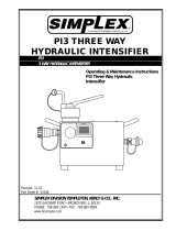
P I T 4
H Y DR A U L I C I N T E N S I F I E R
SIMPLEX DIVISION OF TEMPLETON, KENL
Y & CO., INC.
2525 GARDNER ROAD
BROADVIEW, IL 60155
PHONE: 708-865-1500 * FAX: 708-865-0894 * www.tksimplex.com
INSTRUCTIONAL SHEET #: 54186
REV. A
02/05
A Division Of Templeton, Kenly & Co., Inc.
OPERATING & MAINTENANCE INSTRUCTIONS

Operating Instructions
Read carefully. Most malfunctions in new equipment are the result of improper
operation and/or improper setup.
Inspection
Visually inspect all components for shipping damage. If any damage is found,
notify the carrier immediately.
Once in operation, a visual inspection for any wear or damage should be
conducted each time. If any unusual wear or damage is noted, remove the tool
from service and bring it to an authorized SIMPLEX Repair Center.
Hydraulic Connections
Loosen lock nut and back out (turn counter-clockwise) relief valve until you hit the
mechanical stop to prevent unintended pressure buildup at startup.
Make sure the hoses and quick coupler connections are tight and secure from
the low pressure power supply (PTO) and Torque Wrench before operating.
NOTE: The coupled hoses for the Torque Wrench are color coded and are
design to fit only one way so that the advance port can only be connected to the
wrench advance port, and the retract port can be connected to the wrench retract
port. An improper connection can cause harm to the tool and/or user.
PIT4 Setup
Once the inspection and connections are made, follow these steps to ensure that
the wrench is properly connected and desire torque setting is achieved.
1. Place the torque wrench on the ground in a secure location.
2. Place the manual valve in the neutral or center position.
3. Activate the low pressure power source (PTO). 2,000 PSI @ 5
gallons/min. is recommended.
4. Shift the control handle to the retract position. The gauge should read
1,500 PSI +/-200 PSI.
5. Bleed the intensifier by cycling the control handle back and forth several
times to bleed the system. Make sure to leave it in each position for 2-3
seconds.
6. Shift the gauge to the advance position, the PSI reading on the gauge
should be at zero, since we turned the relief valve counter clockwise to the
mechanical stop under the hydraulic connections section. Gradually turn
the adjusting knob clockwise and look for a pressure increase. Adjust it to
the desired torque setting. Note: the shroud cover is laser engraved to

view PSI vs. Output Torque inch. Once the desired pressure output is
achieved, cycle the wrench to retract and then back to advance to make
sure that the pressure output is correct. Adjust accordingly until desired
pressure is achieved.
7. Return the control handle back to the retract side.
Maintenance
General Cleaning and wiping the couplers is recommended each time in service
prior to coupling the unit to the hydraulic hoses.
Flushing the intensifier is only necessary if contamination has occurred. Refer to
your Truck Body Maintenance for flushing procedures.
Troubleshooting
Problem Cause - Solution
Intensifier Fails to operate
• Make sure the PTO is turned on.
• Check pressure and tank
connections at the PTO
(2,000PSi @ 5Gal/min flow).
• Check for a loose connection at
the hydraulic hose connections.
• Take the unit into a SIMPLEX
Repair Center for further testing.
Intensifier Operates, but fails to build
pressure
• Incorrect pressure off the PTO,
check pressure at the PTO
(2,000PSi @ 5Gal/min flow).
• Check for a loose connection at
the hydraulic hose connections.
• Is the control handle in the
advance position?
• Is the adjusting knob turned all
the way out counter clockwise?
If so, turn clockwise to increase
desired pressure setting.
• Take the unit into a SIMPLEX
Repair Center for further testing.
REFER TO TORQUE WRENCH OPERATING INSTRUCTIONS FOR WRENCH
PROCEDURES.

A Division Of Templeton, Kenly & Co., Inc.
E
Q
U
I
P
M
E
N
T
S
E
R
V
I
C
E
A
S
S
O
C
I
A
T
I
O
N
R
E
B
U
I
L
D
E
R
S
O
F
T
O
O
L
S
&
E
Q
U
I
P
M
E
N
T
U
S
A
M
E
M
B
E
R
C
A
N
A
D
A
PART SHEET #': 54186
REV. A
02/05
PIT4 - TORQUE WRENCH INTENSIFIER
REPAIR PART SHEET

ITEM PART # DESCRIPTION QTY
01 43762 VALVE ROTOR 1.00
02 68026 THRUST WASHER 2.00
03 68155 THRUST BEARING 1.00
04 5602012 O-RING 3/8X1/2 1.00
05 43962 UPPER VALVE BLOCK 1.00
07 68025 DETENT SPRING 1.00
08 92549 BALL 1/4" 1.00
09 45040 VALVE HANDLE RAIL PULLER 1.00
10 45172 HHCS 10-24X1/2 WITH LOCK WASHER 1.00
43964 4 WAY VALVE ASSEMBLY

ITEM PART # DESCRIPTION QTY
01 45675 MANIFOLD TORQUE WRENCH INTENSIFIER 1.00
02 40049 1/16 PIPE PLUG-FLUSH 4.00
03 81093 PIPE PLUG 1/8" FLUSH 2.00
04 68004 SEAT - EXT RELIEF 1.00
05 68003 CONE - EXT RELIEF 1.00
06 66085 SPRING - RELIEF VALVE 1.00
07 66083 RELIEF VALVE ADJUSTING SCREW 1.00
08 86269 GASKET 29/64 X 5/8 1.00
09 69105 ACORN NUT 7/16-20 PL 1.00
45677 - MAINFOLD ASSEMBLY

ITEM PART # DESCRIPTION QTY
01 42773 MANIFOLD BLOCK INT. 1.00
02 81093 PIPE PLUG 1/8" FLUSH 5.00
03 68245 SHCS 3/8-24X 1/2 LG 1.00
04 85726 GASKET 25/64X19/32 1.00
05 45679 SET SCREW 3/8-24 x 3/8" 1.00
07 91701 BALL 5/16" 1.00
08 84084 PIPE PLUG 3/8" FLUSH 1.00
09 43274 POW'R BUD ADJ SCREW 1.00
10 5602012 O-RING 3/8X1/2 1.00
11 66085 SPRING - RELIEF VALVE 1.00
12 68003 CONE - EXT RELIEF 1.00
13 68004 SEAT - EXT RELIEF 1.00
45678 - MANIFOLD SUB-ASSEMBLY

SIMPLEX products are warranted to be free of defects in materials and workmanship under normal use for as long as the original purchaser owns them,
subject to the guidelines and limitations listed. This warranty does not cover: normal wear & tear, cosmetic items, abuse, overloading, alterations,
improper fluid, or use in a manner for which they are not intended. If the customer believes a product is defective, the product must be delivered, or
shipped freight prepaid, to the nearest SIMPLEX Authorized Service Center for evaluation and repair.
2525 GARDNER ROAD * BROADVIEW * ILLINOIS * 60155 * PHONE (708) 865-1500 * FAX (708) 865-0894
S
E
R
V
I
N
G
I
N
D
U
S
T
R
Y
W
I
T
H
P
R
I
D
E
Q
U
A
L
I
T
Y
T
e
m
p
l
e
t
o
n
K
e
n
l
y
&
C
o
.
,
I
n
c
.
S
I
N
C
E
-
1
8
9
9
ITEM PART # DESCRIPTION QTY
01 42773 MANIFOLD BLOCK INT. 1.00
02 81093 PIPE PLUG 1/8" FLUSH 5.00
03 68245 SHCS 3/8-24X 1/2 LG 1.00
04 85726 GASKET 25/64X19/32 1.00
05 45679 SET SCREW 3/8-24 x 3/8" 1.00
07 91701 BALL 5/16" 1.00
08 84084 PIPE PLUG 3/8" FLUSH 1.00
09 43274 POW'R BUD ADJ SCREW 1.00
10 5602012 O-RING 3/8X1/2 1.00
11 66085 SPRING - RELIEF VALVE 1.00
12 68003 CONE - EXT RELIEF 1.00
13 68004 SEAT - EXT RELIEF 1.00
45678 - MANIFOLD SUB-ASSEMBLY
/


