Page is loading ...

For warranty informaon please visit: hp://www.kichler.com/warranty
IS-16236-US
We’re here to help 866-558-5706
Hrs: M-F 9am to 5pm EST
Kichler 16236, 16237, 16238 Installaon Guide
LED Slim Wallpack
IMPORTANT: Read before removing xture from carton. Retain for
future reference.
SAFETY: This xture must be wired in accordance with the
NATIONAL ELECTRICAL CODE (NEC) and applicable local codes and
ordinances. A person familiar with the construcon and operaon
of the product and the hazards involved must install this product.
A qualied licensed electrician should complete all work. Proper
grounding is required for safety.
WARNING: Make certain power is OFF before installing or
maintaining xture.
RISK OF INJURY: Fixture may become damaged and/or unstable if
not installed properly.
Cauons:
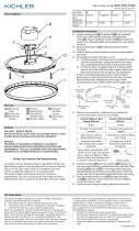
Installaon Instrucons:Fixture Diagram
NOTE: Turn o electrical supply at the breaker. Follow all local
electrical codes for wiring and grounding requirements.
Tools Required: 1/8” Allen Key, Phillips Screw Driver, Wire
Strippers & Cuers
NOTE: Unpack xture and ensure that there are no damaged parts.
FCC Informaon:
RISK OF FIRE, EXPLOSION AND ELECTRIC SHOCK
• This product should be installed, inspected, and maintained by a qualied
electrician only, in accordance with the NEC (Naonal Electric Code) and all
local codes.
• Turn o electrical power before inspecon, installaon or removal.
• Use only UL (or other NRTL) approved wire for input/output connecons.
Minimum size 18 AWG or 14 AWG for connuous runs.
• Make sure LEDs and drivers are cool to touch when performing maintenance.
Make sure the supply voltage is the same as the rated voltage of the luminaire.
• Do not install in a hazardous atmosphere, except where the ambient
temperature does not exceed the rated operang temperature of the xture.
• Keep ghtly closed when in operaon
Electrical Requirements
The LED driver must be supplied with 120 to
277V, 50/60 Hz and connected to an individual,
properly grounded branch circuit protected by a
20 Ampere circuit breaker. Use min. 90°C supply.
Grounding Instrucons
The grounding and bonding of the overall
system shall be done in accordance with NEC
Arcle 600 and local codes
Black
Line
White
Neutral
Green
Ground
FIXTURE
Figure 1
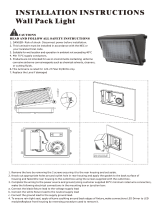
Direct mount to Juncon Box:
1) Remove the boom quick mounng plate from the xture to
install onto juncon box.
2) Apply xture to mounng surface by fastening mounng plate
to recessed juncon box. Use integral bubble level to ensure
that the plate is level.
3) Connect leads from back of xture to the power supply leads:
Green to green (ground), black to black (hot), white to white
(neutral).
4) Take care to not pinch any wires when connecng the xture to
the mounng plate.
5) Tighten Allen set screws on front of xture to secure to the
mounng plate.
6) For wet locaons, caulk between the rear housing and
mounng surface for a water ght seal.
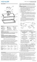
Using Oponal 16256AZT Wall Mount
Extension Juncon Box:
NOTE: Quick mounng plate not required.
1) Apply extension juncon box to mounng surface (two opons).
a. Recessed juncon box: Fasten extension juncon box
to recessed juncon box.
b. Conduit feed: Fasten extension juncon box to desired
surface and remove appropriate threaded conduit plug
and route conduit and circuit wiring into the extension
juncon box using appropriate methods.
2) Connect leads from back of xture to the power supply leads:
Green to green (ground), black to black (hot), white to white
(neutral).
3) Arrange connected wires into extension juncon box.
4) Aach xture to extension juncon box. Take care to not pinch
any wires when connecng the xture.
5) Tighten Allen set screws on front of xture to secure to the
extension juncon box.
6) For wet locaons, caulk between the rear housing and mounng
surface for a water ght seal.
Using Oponal 16292AZT
Trunnion Mount:
NOTE: Quick mounng plate not required.
1) Connect leads from back of xture to
the power supply leads: Green to green
(ground), black to black (hot), white to
white(neutral).
2) Arrange connected wires into trunnion
juncon box.
3) Aach xture to trunnion extension
juncon box. Take care to not pinch any
wires when connecng the xture.
4) Mount the trunnion with appropriate
fasteners to selected surface. Mounng
slots are ½”.
5) Loosen pivot screws to adjust angle of
xture to desired posion. Reghten pivot
screws.
This device complies with part 15 of the FCC Rules. Operaon is subject to the following two condions:
1) This device may not cause harmful interference, and
2) This device must accept any interference received, including interference that may cause
undesired operaon.
Note: This equipment has been tested and found to comply with the limits for a Class A digital device,
pursuant to part 15 of the FCC Rules. These limits are designed to provide reasonable protecon against
harmful interference in a residenal installaon. This equipment generates, uses and can radiate radio
frequency energy and, if not installed and used in accordance with the instrucons, may cause harmful
interference to radio communicaons.
However, there is no guarantee that interference will not occur in a parcular installaon. If this
equipment does cause harmful interference to radio or television recepon, which can be determined
by turning the equipment o and on, the user is encouraged to try to correct the interference by one or
more of the following measures:
• Reorient or relocate the receiving antenna.
• Increase the separaon between the equipment and receiver.
• Connect the equipment into an outlet on a circuit dierent from that to which the receiver is
connected.
• Consult the dealer or an experienced radio/TV technician for help.

IS-16236-CB
For warranty informaon please visit: hp://www.kichler.com/warranty
We’re here to help 866-558-5706
Hrs: M-F 9am to 5pm EST
Kichler 16236, 16237, 16238 Installaon Guide
LED Slim Wallpack
IMPORTANT: Read before removing xture from carton. Retain for
future reference.
SAFETY: This xture must be wired in accordance with the
NATIONAL ELECTRICAL CODE (NEC) and applicable local codes and
ordinances. A person familiar with the construcon and operaon
of the product and the hazards involved must install this product.
A qualied licensed electrician should complete all work. Proper
grounding is required for safety.
WARNING: Make certain power is OFF before installing or
maintaining xture.
RISK OF INJURY: Fixture may become damaged and/or unstable if
not installed properly.
Cauons:
Installaon Instrucons:Fixture Diagram
NOTE: Turn o electrical supply at the breaker. Follow all local
electrical codes for wiring and grounding requirements.
Tools Required: 1/8” Allen Key, Phillips Screw Driver, Wire
Strippers & Cuers
NOTE: Unpack xture and ensure that there are no damaged parts.
FCC Informaon:
RISK OF FIRE, EXPLOSION AND ELECTRIC SHOCK
• This product should be installed, inspected, and maintained by a qualied
electrician only, in accordance with the NEC (Naonal Electric Code) and all
local codes.
• Turn o electrical power before inspecon, installaon or removal.
• Use only UL (or other NRTL) approved wire for input/output connecons.
Minimum size 18 AWG or 14 AWG for connuous runs.
• Make sure LEDs and drivers are cool to touch when performing maintenance.
Make sure the supply voltage is the same as the rated voltage of the luminaire.
• Do not install in a hazardous atmosphere, except where the ambient
temperature does not exceed the rated operang temperature of the xture.
• Keep ghtly closed when in operaon
Electrical Requirements
The LED driver must be supplied with 120 to
277V, 50/60 Hz and connected to an individual,
properly grounded branch circuit protected by a
20 Ampere circuit breaker. Use min. 90°C supply.
Grounding Instrucons
The grounding and bonding of the overall
system shall be done in accordance with NEC
Arcle 600 and local codes
Black
Line
White
Neutral
Green
Ground
FIXTURE
Figure 1
Direct mount to Juncon Box:
1) Remove the boom quick mounng plate from the xture to
install onto juncon box.
2) Apply xture to mounng surface by fastening mounng plate
to recessed juncon box. Use integral bubble level to ensure
that the plate is level.
3) Connect leads from back of xture to the power supply leads:
Green to green (ground), black to black (hot), white to white
(neutral).
4) Take care to not pinch any wires when connecng the xture to
the mounng plate.
5) Tighten Allen set screws on front of xture to secure to the
mounng plate.
6) For wet locaons, caulk between the rear housing and
mounng surface for a water ght seal.
Using Oponal 16256AZT Wall Mount
Extension Juncon Box:
NOTE: Quick mounng plate not required.
1) Apply extension juncon box to mounng surface (two opons).
a. Recessed juncon box: Fasten extension juncon box
to recessed juncon box.
b. Conduit feed: Fasten extension juncon box to desired
surface and remove appropriate threaded conduit plug
and route conduit and circuit wiring into the extension
juncon box using appropriate methods.
2) Connect leads from back of xture to the power supply leads:
Green to green (ground), black to black (hot), white to white
(neutral).
3) Arrange connected wires into extension juncon box.
4) Aach xture to extension juncon box. Take care to not pinch
any wires when connecng the xture.
5) Tighten Allen set screws on front of xture to secure to the
extension juncon box.
6) For wet locaons, caulk between the rear housing and mounng
surface for a water ght seal.
Using Oponal 16292AZT
Trunnion Mount:
NOTE: Quick mounng plate not required.
1) Connect leads from back of xture to
the power supply leads: Green to green
(ground), black to black (hot), white to
white(neutral).
2) Arrange connected wires into trunnion
juncon box.
3) Aach xture to trunnion extension
juncon box. Take care to not pinch any
wires when connecng the xture.
4) Mount the trunnion with appropriate
fasteners to selected surface. Mounng
slots are ½”.
5) Loosen pivot screws to adjust angle of
xture to desired posion. Reghten pivot
screws.
This device complies with part 15 of the FCC Rules. Operaon is subject to the following two condions:
1) This device may not cause harmful interference, and
2) This device must accept any interference received, including interference that may cause
undesired operaon.
Note: This equipment has been tested and found to comply with the limits for a Class A digital device,
pursuant to part 15 of the FCC Rules. These limits are designed to provide reasonable protecon against
harmful interference in a residenal installaon. This equipment generates, uses and can radiate radio
frequency energy and, if not installed and used in accordance with the instrucons, may cause harmful
interference to radio communicaons.
However, there is no guarantee that interference will not occur in a parcular installaon. If this
equipment does cause harmful interference to radio or television recepon, which can be determined
by turning the equipment o and on, the user is encouraged to try to correct the interference by one or
more of the following measures:
• Reorient or relocate the receiving antenna.
• Increase the separaon between the equipment and receiver.
• Connect the equipment into an outlet on a circuit dierent from that to which the receiver is
connected.
• Consult the dealer or an experienced radio/TV technician for help.
/