Page is loading ...

IS-86002-US
We’re here to help 866-558-5706
Hrs: M-F 9am to 5pm EST
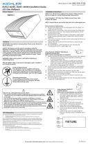
16.8
[
427.2
]
9.0
[
228.6
]
B
E
A
C
D
1) Use provided paper template[A] to locate the desired
mounng locaon for the mirror and to mark the locaons
required for the wall anchors. NOTE: The mirror can be
mounted in a horizontal or vercal posion. Vercal posion
is shown.
2) Use a 15/64 inch drill bit to drill pilot holes at the locaons
marked in step 1 and insert wall anchors[C].
3) Screw all but 1/8 inch length of each wood screw[D] into the
wall anchors.
4) Grounding instrucons
Aach ground wire to outlet box.
GREEN GROUND
SCREW
CUPPED
WASHER
OUTLET BOX
GROUND
FIXTURE
GROUND
DIMPLES
WIRE CONNECTOR
OUTLET BOX
GROUND
GREEN GROUND
SCREW
FIXTURE
GROUND
a
b
Fixture Diagram
Parts List
[A] Paper
Template
[B] Mirror
[C] Wall Anchors
[D] Wood Screw
[E] Switch
Cauons
CAUTION – RISK OF SHOCK –
Disconnect Power at the main circuit breaker panel or main
fusebox before starng and during the installaon.
WARNING:
This xture is intended for installaon in accordance with the
Naonal Electrical Code (NEC) and all local code specicaons.
If you are not familiar with code requirements, installaon by a
cered electrician is recommended.
DIMMING:
This LED xture is compable with most standard incandescent
dimmers, LED dimmers, and electronic low voltage dimmers.
For opmal performance, an electronic low voltage dimmer should
be used.
CLEANING:
Always be certain that electric current is turned o before cleaning.
• Only a so damp cloth should be used. Harsh cleaning
products may damage the nish.
Installaon Instrucons
This device complies with part 15 of the FCC Rules. Operaon is subject to the
following two condions:
1) This device may not cause harmful interference, and
2) This device must accept any interference received, including interference that
may cause undesired operaon.
Note: This equipment has been tested and found to comply with the limits for a
Class B digital device, pursuant to part 15 of the FCC Rules. These limits are designed
to provide reasonable protecon against harmful interference in a residenal
installaon. This equipment generates, uses and can radiate radio frequency
energy and, if not installed and used in accordance with the instrucons, may cause
harmful interference to radio communicaons. However, there is no guarantee that
interference will not occur in a parcular installaon. If this equipment does cause
harmful interference to radio or television recepon, which can be determined
by turning the equipment o and on, the user is encouraged to try to correct the
interference by one or more of the following measures:
• Reorient or relocate the receiving antenna.
• Increase the separaon between the equipment and receiver.
• Connect the equipment into an outlet on a circuit dierent from that to which
the receiver is connected.
• Consult the dealer or an experienced radio/TV technician for help.
FCC Informaon:
For warranty informaon please visit: kichler.com/warranty
TEMPLATE
UP
Installaon Instrucons (connued)
If xture is provided with ground wire, connect xture ground
wire to outlet box ground wire with wire connector aer
following the above steps. Never connect ground wire to black
or white power supply wires.
Please contact a qualied licensed electrical contractor to
ensure installaon meets naonal electrical code NFPA70.
Juncon boxes should be covered and wires entering or exing
the box should be secured. Instrucons below are for a typical
install.
• Remove the 4 screws around the edge of the mirror frame
and remove face of mirror.
• Remove the knockout in the back of the mirror located over
the juncon box.
• Install a NM cable connector clamp (not included) into the
knockout hole.
• Pass the mirror jumper wire through the clamp and secure.
• Aach the mirror jumper cable’s wires to the juncon box
supply wires as follows:
- WHITE (NEUTRAL) MIRROR JUMPER WIRE TO THE WHITE
SUPPLY WIRE.
- BLACK (LIVE) MIRROR JUMPER WIRE TO THE BLACK SUPPLY
WIRE.
- GREEN OR BARE COPPER (GROUND) MIRROR JUMPER WIRE
TO THE BARE COPPER WIRE.
5) Hang mirror[B] by the keyhole slots in the back of the mirror.
NOTE: the mirror should be oriented so that the narrow
poron of the keyhole faces up.
6) To change the light output of your mirror, tap the switch[E] on
the boom of the mirror or gently press the switch. The switch
is a touch dimming switch.
TEMPLATE
UP
/