Page is loading ...

This device complies with part 15 of the FCC Rules. Operation is
subject to the following two conditions: (1) This device may not
cause harmful interference, and (2) this device must accept any
interference received, including interference that may cause un-
desired operation.
Before Installing:
All installations should comply with National and local electrical
codes.
If you have any doubts concerning installation contact a qualified li-
censed electrician.
1) TURN OFF POWER.
IMPORTANT: Before you start, NEVER attempt any work
without shutting off the electricity until the work is done.
a) Go to the main fuse, or circuit breaker, box in your home.
Place the main power switch in the “OFF” position.
b) Unscrew the fuse(s), or switch “OFF” the circuit breaker
switch(s), that control the power to the fixture or room
that you are working on.
c) Place the wall switch in the “OFF” position. If the fixture
to be re placed has a switch or pull chain, place those in
the “OFF” position.
2) For wet location applications, apply a generous bead of
silicone sealant on the back of the mounting plate around
the outlet box openings and lag screw openings. Caulking
may be omitted if fixture is being installed indoors.
3) Press the mounting plate against the wall, centered over the
outlet box. Attach mounting plate to outlet box with screws
provided. Two lag screw openings are also provided in the
mounting plate. Install appropriate fasteners through these
openings into the wall surface, to assure proper fixture
retention. (Lag screws not provided)
4) Attach the grounding conductor to the raised grounding lug
on the back of the fixture housing. Secure by tightening the
green screw. Never connect black or white power supply
wires to the grounding lug.
5) Connect the black fixture wires to the black supply wire with
a suitable wire connector (not provided). Connect the white
fixture wires to the white supply wire with a suitable connector.
6) Attach the fixture to the mounting plate using the 4 screws
provided. Note that these screws include small rubber O-rings,
to prevent water from entering the fixture. Make sure the
O-rings are in place before installing screws. Apply pressure
towards the wall to compress an internal gasket. This will
allow the 4 screws to align with the mounting plate tabs.
Este dispositivo cumple con la parte 15 de las Reglas de la Comis-
ión Federal de Comunicaciones (FCC – por sus siglas en inglés).
La operación está sujeta a las dos condiciones siguientes: (1)
Este dispositivo no podrá ocasionar interferencias perjudiciales, y
(2) este dispositivo tiene que aceptar cualquier interferencia re-
cibida, incluyendo interferencias que podrán ocasionar una op-
eración indeseada.
Antes de instalar:
Todas las instalaciones deberán cumplir con los códigos eléctri-
cos nacional y local.
Si tiene dudas en relación con la instalación contacte a un electr-
icista calificado con licencia.
1) APAGUE LA ENERGÍA ELÉCTRICA.
IMPORTANTE: Antes de que usted empiece, NUNCA intente
cualquier trabajo sin antes cortar la electricidad hasta que el
trabajo haya sido realizado.
a) Vaya a la caja del fusible principal, o interruptor de
circuito, en su hogar. Coloque el interruptor de energía
principal en la posición de “APAGADO” (“OFF”).
b) Desenrosque el(los) fusible(s), o mueva hacia la posición
de “APAGADO” (“OFF”) el interruptor de circuito, que
controla la energía eléctrica hacia el dispositivo o
habitación en donde usted está trabajando.
c) Coloque el interruptor de pared en la posición de
“APAGADO” (“OFF”). Si el dispositivo que será reemplazado
tiene un interruptor o una cadena para jalar, coloque
estos en la posición de “APAGADO” (“OFF”).
INSTALLATION INSTRUCTIONS / INSTRUCCIONES DE INSTALACIÓN
Model 49492 / CP150833
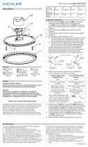
MOUNTING PLATE
PLACA DE MONTAJE
OUTLET BOX
CAJA DE
CONEXIONES
SCREWS
TORNILLOS
OUTLET BOX
SCREWS
TORNILOOS DE
LA CAJA DE
CONEXIONES
LAG SCREW
OPENING
ABERTURA
PARA TORNILLO
PUNTIAGUDO
FIXTURE
ARTEFACTO
Date Issued: 4/18/14
IS-49492-US
We’re here to help 866-558-5706
Hrs: M-F 9am to 5pm EST
2) Para las aplicaciones de ubicaciones húmedas, aplique una
gota generosa de sellador de silicón sobre la parte trasera
de la placa de montaje alrededor de las aberturas de la caja
de conexiones y de los tornillos puntiagudos. Se puede
omitir el sellador si el artefacto se instala adentro.
3) Presione la placa de montaje contra la pared, centrada sobre
la caja de conexiones. Fije la placa de montaje a la caja de
conexiones con los tornillos suministrados. También se
proporcionan dos aberturas para tornillos puntiagudos en la
placa de montaje. Instale los cierres apropiados a través de
estas aberturas dentro de la superficie de la pared, para
asegurar la retención apropiada del artefacto. (No se
proporcionan los tornillos puntiagudos).
4) Fije el conductor de conexión a tierra al terminal a tierra
elevado en la parte trasera de la carcasa del artefacto.
Asegúrelo apretando el tornillo verde. Nunca conecte los
alambres de suministro de energía negros o blancos al
terminal a tierra.
5) Conecte los alambres negros del artefacto al alambre de
suministro negro con un conector de alambre adecuado (no
se proporciona). Conecte los alambres blancos del artefacto
al alambre de suministro blanco con un conector de alambre
adecuado.
6) Fije el artefacto a la placa de montaje utilizando los 4
tornillos suministrados. Observe que estos tornillos incluyen
anillos en “O” de goma pequeños, para evitar que entre
agua al artefacto. Asegúrese que los anillos en “O” están en
su lugar antes de instalar los tornillos. Aplique presión hacia
la pared para comprimir una junta interna. Esto permitirá
que los 4 tornillos estén alineados con las pestañas de la
placa de montaje.
LAG SCREW OPENING
ABERTURA PARA
TORNILLO PUNTIAGUDO

This device complies with part 15 of the FCC Rules. Operation is
subject to the following two conditions: (1) This device may not
cause harmful interference, and (2) this device must accept any
interference received, including interference that may cause un-
desired operation.
Before Installing:
All installations should comply with National and local electrical
codes.
If you have any doubts concerning installation contact a qualified li-
censed electrician.
1) TURN OFF POWER.
IMPORTANT: Before you start, NEVER attempt any work
without shutting off the electricity until the work is done.
a) Go to the main fuse, or circuit breaker, box in your home.
Place the main power switch in the “OFF” position.
b) Unscrew the fuse(s), or switch “OFF” the circuit breaker
switch(s), that control the power to the fixture or room
that you are working on.
c) Place the wall switch in the “OFF” position. If the fixture
to be re placed has a switch or pull chain, place those in
the “OFF” position.
2) For wet location applications, apply a generous bead of
silicone sealant on the back of the mounting plate around
the outlet box openings and lag screw openings. Caulking
may be omitted if fixture is being installed indoors.
3) Press the mounting plate against the wall, centered over the
outlet box. Attach mounting plate to outlet box with screws
provided. Two lag screw openings are also provided in the
mounting plate. Install appropriate fasteners through these
openings into the wall surface, to assure proper fixture
retention. (Lag screws not provided)
4) Attach the grounding conductor to the raised grounding lug
on the back of the fixture housing. Secure by tightening the
green screw. Never connect black or white power supply
wires to the grounding lug.
5) Connect the black fixture wires to the black supply wire with
a suitable wire connector (not provided). Connect the white
fixture wires to the white supply wire with a suitable connector.
6) Attach the fixture to the mounting plate using the 4 screws
provided. Note that these screws include small rubber O-rings,
to prevent water from entering the fixture. Make sure the
O-rings are in place before installing screws. Apply pressure
towards the wall to compress an internal gasket. This will
allow the 4 screws to align with the mounting plate tabs.
Cet appareil est conforme à la section 15 de la réglementation de
la FCC. Son fonctionnement est soumis aux deux conditions suiv-
antes : (1) Cet appareil ne doit pas causer d’interférences nuisi-
bles, et (2) cet appareil doit accepter toute interférence reçue, y
compris les interférences risquant d’engendrer un fonctionne-
ment indésirable.
Avant de procéder à l’installation:
Toutes les installations doivent être conformes aux codes
électriques nationaux et locaux.
En cas de doute concernant l’installation, contacter un électric-
ien qualifié.
1) COUPER LE COURANT.
IMPORTANT: TOUJOURS couper l’électricité avant de
commencer le travail.
a) Localiser le coffret à fusibles ou le disjoncteur du
domicile. Mettre l’interrupteur principal en position d’Arrêt.
b) Dévisser le ou les fusibles (ou mettre le disjoncteur sur
Arrêt) qui contrôlent l’alimentation vers le luminaire ou la
pièce dans laquelle le travail est effectué.
c) Mettre l’interrupteur mural en position d’Arrêt. Si le
luminaire à remplacer est doté d’un interrupteur ou
d’une chaîne connectée à l‘interrupteur, placer ces
éléments en position d’Arrêt.
2) Pour les emplacements mouillés, appliquer un trait du
produit d’étanchéité à base de silicone sur la partie arrière
de la plaque de montage autour des ouvertures du boîtier
de sortie et de celles de la vis tire-fond. Il est possible de
supprimer l’étape du calfeutrage si le luminaire est installé à
l’intérieur.
INSTALLATION INSTRUCTIONS / INSTRUCTIONS D’INSTALLATION
Model 49492 / CP150833
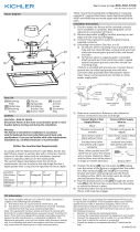
MOUNTING PLATE
PLAQUE DE MONTAGE
OUTLET BOX
BOÎTIER DE
SORTIE
SCREWS
VIS
OUTLET BOX
SCREWS
VIS DE BOÎTIER
DE SORTIE
LAG SCREW
OPENING
OUVERTURE DE
VIS TIRE-FOND
FIXTURE
LUMINAIRE
Date Issued: 4/18/14
IS-49492-CB
We’re here to help 866-558-5706
Hrs: M-F 9am to 5pm EST
3) Appuyer sur la plaque de montage pour la coller contre le
mur en la centrant sur le boîtier de sortie. Fixer la plaque de
montage sur le boîtier de sortie avec les vis fournies. Deux
ouvertures de vis tire-fond sont également fournies dans la
plaque de montage. Installer les fixations appropriées par
ces ouvertures dans le mur pour garantir une bonne fixation
du luminaire. (Vis tire-fond non fournies)
4) Fixer le conducteur de mise à la terre sur la cosse de mise à
la terre relevée située à l’arrière du boîtier du luminaire. Fixer
en serrant la vis verte. Ne jamais connecter les fils d’alimentation
noirs ou blanc à la cosse de mise à la terre.
5) Connecter les fils noirs du luminaire au fil noir de l’alimentation
avec un connecteur de fil approprié (non fourni). Connecter
les fils blancs du luminaire au fil blanc d’alimentation avec
un connecteur approprié.
6) Fixer le luminaire à la plaque de montage à l’aide des 4 vis
(fournies). Remarquer que ces vis incluent des joints toriques
de petite taille afin d’empêcher l’eau de pénétrer dans le
luminaire. S’assurer que les joints toriques sont en place
avant d’installer les vis. Exercer une pression en direction du
mur pour comprimer le joint interne. Les 4 vis s’aligneront
ainsi aux languettes de la plaque de montage.
LAG SCREW OPENING
OUVERTURE DE
VIS TIRE-FOND
INSTRUCTIONS
For Assembling and Installing Fixtures in Canada
Pour L’assemblage et L’installation Au Canada
/