SunTouch 24004830R User manual

Type
User manual
INSTALLATION MANUAL
888-432-8932
www.suntouch.com/diy
Please be aware local codes may require this product and/or the thermostatic control to be installed or connected by an electrician. Please leave this manual with the end user.
Do It Yourself
FLOOR WARMING
Series D12
2
SunTouch Mat Do It Yourself Manual
Welcome to SunTouch®!
SunTouch floor heating mats are a simple way to heat an indoor space. This instruction manual is provided as a guide to installing
SunTouch Mats, including design considerations, installation steps, limitations, precautions, and floor covering guidelines.
Specifications for SunTouch Mat:
SunTouch Mat is a complete heating mat consisting of a series
heating wire and a power lead for connection to the electric
power supply. The heating wire length cannot be cut to fit.
Controls: SunTouch Mats must be controlled by a SunStat®
floor sensing thermostat.
Voltage: 120 VAC, 240 VAC, 1-phase (see Table 2)
Watts: 12 W/sqft (41 Btu/h/sqft)
Maximum circuit load: 15 A
Maximum circuit overload protection: 20 A breaker
GFCI: (Ground Fault Circuit Interrupter) required for each
circuit (included in the SunStat control)
Listing: UL Listed for U.S. and Canada under UL 1693 and
CAN/CSA C22.2 No. 130-03, File No. E185866
Application: Type (X) (See UL Name Plate Label on product)
For indoor floor heating application only. Only embedded in polymer modified cement based mortar . UL Listed to U.S.
Standards only for installation into a shower area. (See 4.10 for details).
Minimum bend radius: 1 inch
Maximum exposure temperature: (Continuous and storage) 194ºF (90ºC)
Minimum installation temperature: 50ºF (10ºC)
Skill Level
Installation must be performed by qualified persons, in accordance with local codes, ANSI/NFPA 70 (NEC Article 424) and CEC Part
1 Section 62 where applicable.
Prior to installation please consult the local codes in order to understand what is acceptable. To the extent this information is not
consistent with local codes, the local codes should be followed. However, electrical wiring is required from a circuit breaker or
other electrical circuit to the control. It is recommended that an electrician perform these installation steps. Please be aware local
codes may require this product and/or the control to be installed by an electrician.
Expected floor temperature
Heating performance is never guaranteed. SunTouch Mat is designed to deliver 12 W/sq.ft. The floor temperature attainable is
dependent on how well the floor is insulated, the temperature of the floor before start up, and the overall thermal drain of the
floor mass. Insulation is required for best performance. Refer to Phase 5 for important design considerations.
You are required to thoroughly read all installation instructions and product safety information before beginning the installation
of this product. FAILURE TO COMPLY WITH PROPER INSTALLATION AND MAINTENANCE INSTRUCTIONS COULD RESULT IN
PROPERTY DAMAGE, PERSONAL INJURY AND/OR DEATH. Watts Radiant is not responsible for damages resulting from improper
installation and/or maintenance.
Heating Wire
Factory Splice
Power lead
Mat Mesh
Table of Contents
Phase 1 - Designing the System .....................................pg 4
Phase 2 - Preparations ..............................................pg 5
Phase 3 - Electrical Rough-in ........................................pg 8
Phase 4 - Mat Installation ............................................pg 9
Phase 5 - Floor Coverings ...........................................pg 13
Phase 6 - Control Installation ........................................pg 15
Appendices ........................................................pg 16
Control Wiring ......................................................pg 19
Connections ........................................................pg 20
Troubleshooting ....................................................pg 21
Warranty ........................................................pg 22
SunTouch Mat Do It Yourself Manual
3
You are required to thoroughly read all installation
instructions and product safety information before
beginning the installation of this product. FAILURE TO
COMPLY WITH PROPER INSTALLATION INSTRUCTIONS
COULD RESULT IN PROPERTY DAMAGE, PERSONAL INJURY
and/or DEATH. Local building or plumbing codes may
require modifications to the information provided. You
are required to consult the local building and plumbing
codes prior to installation. If this information is not
consistent with local building or plumbing codes, the
local codes should be followed.
Watts Radiant is not responsible for damages resulting
from improper installation and/or maintenance.
NOTE: Electrical wiring is required. Watts Radiant
recommends consulting with a licensed electrician prior
to installation. Specifically, it is recommended that an
electrician perform all electrical wiring from the circuit
breaker or other electrical circuit to the control. Please be
aware that local codes may require that this product is
installed by a licensed professional.
NEVER install SunTouch Mat under carpet, wood, vinyl,
or other non-masonry flooring without embedding
it in thin-set, thick-set, or self-leveling mortar.
NEVER install SunTouch Mat in adhesives or glues
intended for vinyl tile or other laminate flooring,
or in pre-mix mortars. It must be embedded in
polymer-modified, cement based mortar.
NEVER cut the heating wire. Doing so will cause
dangerous overheating and will void the warranty.
The power lead may be cut shorter if necessary, but
never remove completely from the heating wire.
NEVER bang a trowel or other tool on the heating wire.
Be careful not to nick, cut, or pinch the wire causing
it to be damaged.
NEVER use nails, staples, or similar to fasten the
heating wire to the floor.
NEVER attempt to repair a damaged heating wire,
splice, or power lead using unauthorized parts. Use
only factory authorized repair parts and methods.
NEVER splice one mat heating wire to another mat
heating wire to make a longer mat. Multiple mat
power leads must be connected in parallel in a
junction box or to the thermostat.
NEVER install one mat on top of another or overlap
the heating wire on itself. This will cause dangerous
overheating.
NEVER forget to install the floor sensor included with
the thermostat.
NEVER install SunTouch Mat in any walls, or over walls
or partitions that extend to the ceiling.
NEVER install mats under cabinets or other built-
ins having no floor clearance, or in small closets.
Excessive heat will build up in these confined
spaces, and the mat can be damaged by fasteners
(nails, screws, etc.) used to install built-ins.
NEVER remove the nameplate label from the power
leads. Make sure it is viewable for inspection later.
NEVER extend the heating wire beyond the room or
area in which it originates.
NEVER allow a power lead or sensor wire to cross over
or under a heating cable. Damage could result.
ALWAYS completely embed the heating wire and
factory splices in the floor mortar.
ALWAYS maintain a minimum of 2" spacing between
heating wires.
ALWAYS pay close attention to voltage and amperage
requirements of the breaker, the thermostat, and
the Mat. For instance, do not supply 240 VAC power
to 120 VAC Mat as damage will result.
ALWAYS make sure all electrical work is done by
qualified persons in accordance with local building
and electrical codes, Section 62 of the Canadian
Electrical Code (CEC) Part I, and the National
Electrical Code (NEC), especially Article 424.
ALWAYS use copper only as supply conductors to the
thermostat. Do not use aluminum.
ALWAYS seek help if a problem arises. If ever in doubt
about the correct installation procedure to follow,
or if the product appears to be damaged, the
factory must be called before proceeding with the
installation.
CAUTIONS!
ReAd BefORe INSTAllINg SUNTOUCH MAT
Table 1
4
SunTouch Mat Do It Yourself Manual
Phase 1: Designing the System
SunTouch Mat should be installed in all interior floor areas
intending to be warmed. It cannot be used for exterior
applications, snow melting, in or on walls, or in ceilings. In many
applications it can be used to heat the room but an accurate
heat-loss calculation must be made to determine if enough
heat will be provided to match the heat loss.
STEP 1.1
Make a sketch of the room and measure the overall room
size. Measurement should be made from wall-to-wall
and include size and location of cabinets, tub, toilets, etc.
Determine the total square footage of floor area to be
warmed by subtracting out the area associated with the built-
ins. Keep in mind the following:
• Heatwillnotradiatebeyondabout1-1/2"oneitherside
of the heating wire, therefore consistent coverage is
important.
• Do install heating wire within about 1-1/2" to 2" from a
counter or vanity in the kick-space to ensure warmth in this
area.
• Do not install the heating wire underneath cabinets or
fixtures having no floor clearance or inside a wall. Excessive
heat will build up and cause damage.
• Do not run the heating wire into small closets or other
confined areas where excessive heat will build up.
• Do not install the heating wires closer than 6" from toilet
rings to avoid possible melting of wax rings.
• Do not directly cross expansion joints.
• Do not place the heating wire any closer than 4" from
other items such as forced air ducting or potable piping to
avoid overheating them.
• SunTouchMatmustbelaidinamannertopreventsurface
obstructions being placed directly over the mat location.
Failure to do so will result in capturing heat and may allow
potential damage from mounting brackets, bolts, or similar
penetrations associated with pedestals, support columns,
walls, or similar.
• Installtheheatingwires4"to6"awayfromtheperimeter
walls of the room. It may be placed closer, but is
unnecessary since most people do not stand this close to
the wall. Make sure the heating wire will not be located
underneath finish trim.
• Theheatingwireandfactorysplicesmustbecompletely
embedded in the thin-set. Only the power lead may exit
the thin-set and enter the wall. Pull power leads through
UL Listed conduit to a UL Listed junction box or the control
box.
STEP 1.2
Multiply the heated area square footage calculated in Step 1.1
by 0.90 to allow 4" to 6" spacing around the edges of the floor
area. Use this resulting square footage to select the appropriate
mats from Table 2 on page 5.
Remember:
• Do not exceed 15 amps at 120 VAC (1800 watts) or 15 amps
(3600 watts) at 240 VAC through a single SunStat.
• Selecteither120VACor240VACdependingonthepower
available. DO NOT mix voltages on the same SunStat if more
than one mat is to be installed to cover an area.
• Loadnomorethan12ampsona15-ampcircuitbreaker,or
15 amps on a 20-amp circuit breaker.
• SeetheWiringDiagramsinAppendixforfurtherinformation.
If the exact size of product calculated is not found in the
selection Table 2 on page 5, it may be necessary to adjust the
warming area(s) or select the next smaller size. Remember, the
heating wire must never be cut shorter to fit, and must be
completely embedded in thin-set, thick-set, or self-leveling
concrete. Failure to do so may result in damage to the
product. Do not select a product larger than necessary.
Small bath design
Gross Room Area: 8 x 5 = 40 sf
Built-in Areas
Sink and Toilet: 2 x 5 = 10 sf
Bath Tub: 2.5x 5 = 12.5 sf
Total Heated Area: 40 - (10 + 12.5) = 17.5 sf
Mat Coverage: 17.5 x 0.90 = 15.75 sf
Chosen Mat Size: 15 sf.
Sink
Toilet
Bath Tub
8 ft
5 ft
2-1/2 ft
5 ft
2 ft
SunTouch Mat Do It Yourself Manual
5
Table 2 (Mat sizes)
120 VAC
Mat Square
Footage
Mat Size
(W x L)
Model
Number
Amp
Draw Ohms
10 30" x 4' 12000430 1.0 114-141
15 30" x 6' 12000630 1.5 74-92
20 30" x 8' 12000830 2.0 57-71
25 30" x 10' 12001030 2.5 44-54
30 30" x 12' 12001230 3.0 34-43
35 30" x 14' 12001430 3.5 29-37
40 30" x 16' 12001630 4.0 25-32
45 30" x 18' 12001830 4.5 22-28
50 30" x 20' 12002030 5.0 20-26
60 30" x 24' 12002430 6.0 17-22
70 30" x 28' 12002830 7.0 14-18
80 30" x 32' 12003230 8.0 12-16
240 VAC
Mat Square
Footage
Mat Size
(W x L) Model Number
Amp
Draw Ohms
20 30" x 8' 24000830 1.0 219-269
30 30" x 12' 24001230 1.5 155-190
40 30" x 16' 24001630 2.0 115-141
50 30" x 20' 24002030 2.5 88-108
60 30" x 24' 24002430 3.0 68-85
70 30" x 28' 24002830 3.5 58-72
80 30" x 32' 24003230 4.0 51-64
90 30" x 36' 24003630 4.5 45-56
100 30" x 40' 24004030 5.0 41-51
120 30" x 48' 24004830 6.0 34-42
140 30" x 56' 24005630 7.0 29-36
160 30" x 64' 24006430 8.0 25-32
It is important to select the proper sized mat for the given area.
Mat cannot be cut shorter in order to fit a given area. Doing so will
damage the heating wire and will prevent the system from working.
Phase 2: Preparations
Before installing SunTouch Mat, make sure to fully inspect the
products and carefully plan the site.
Items Needed
Materials:
- SunStat thermostat control with floor sensor. The SunStat is
listed separately from the Mat.
- 20-amp circuit breaker
- UL Listed electrical box (extra deep) for the control; single-
gang (not a gangable type) for one or two mats or 4"-square
deep box with a single-gang “mud ring cover
- 4" junction box with a cover (if needed)
- Flexible or rigid UL Listed conduit (for new construction)
- 12-gauge or 14-gauge electrical wiring cable (consult local
code)
- Wire nuts if using an additional junction box
- Nail plate
Tools:
- Digital multi-meter for ohms testing; must read up to 20,000
ohms to measure sensor
- Drill with 1/2" & 3/4" bits
- Hammer and chisel
- Wire strippers
- Phillips screwdriver
- Fish tape
- Hole saw
- Floor covering installation tools
STEP 1.3
Make sure proper subfloor materials are selected in accordance
with the construction and floor covering requirements. Use of
a moisture barrier, an anti-fracture membrane, backerboard, or
other materials are recommended when installing tile or other
stone floor covering.
STEP 1.4
Pay careful attention to the total amps when selecting multiple
mats to make sure the controls, circuit breaker panel, and all
wiring have the proper capacity. Design circuit protection and
wiring to handle 125% of total amp load.
6
SunTouch Mat Do It Yourself Manual
INSPECT MAT, CONTROL, and SENSOR
STEP 2.1
Remove the Mat, SunStat control, and SunStat sensor from
their packages. Inspect them for any visible damage and
verify everything is the correct size and type according to
the plan and the order. Do not attempt to install a damaged
product.
STEP 2.2
Record the product information in Table 4. Give this
information to the homeowner to keep in a safe place.
The mat model number, serial number, voltage, and
resistance range are shown on a nameplate label attached
to the power leads, as well as the marking “(x)-FOR INDOOR
FLOOR HEATING APPLICATIONS”.
Do not remove this nameplate label. The electrical
inspector will need to see this.
STEP 2.3
Use a digital multi-meter set to the 200 or 2000 (2k)
range to measure the resistance between the conductors
of the mat power leads. Record these resistances in Table 4
under “Out of the box before installation.
The resistance should measure within the resistance range on
the nameplate label. If it is a little low, it may be due to low
air temperatures or meter calibration. Consult the factory if in
doubt.
WARNING: To prevent the risk of personal injury
and/or death, make sure power is not applied to the
product until it is fully installed and ready for final
testing. All work must be done with power turned off
to the circuit being worked on.
Record the information from
the nameplate label into the
Mat and Sensor Resistance
Log. Leave the nameplate label
attached to the power leads for
later inspection.
Press the test lead tips to the Black and White (or Blue for 240 VAC) power lead wires.
This reading should correspond to the factory resistance range on the nameplate label
attached to the Power lead.
Readings between the Black and Ground and the White (or Blue for 240 VAC) and
Ground power lead wires should measure “open, or “O.L, or the same as displayed when
the test leads are not touching anything.
Black Lead
White or Blue Lead
Ground Lead
Black Lead
200 ohm setting
Black wire to COM
Red wire to Ω
White or Blue Lead
Ground Lead
Black Lead
White or Blue Lead
Ground Lead
SunTouch Mat Do It Yourself Manual
7
Measure the resistance between either of the white or
black leads and ground lead. This measurement should be
open”, usually indicated by an “OL or a “I”. This is the same as
displayed when the test leads are not touching anything.
If there is any change in the reading, record this information
and contact the factory before continuing. This could indicate
damage, test lead problems, or a number of other issues. Try
“pinning the test leads to the cable lead wires against a hard
non-metal surface if the readings continue to fluctuate.
Change the meter to the 20,000 ohms (20 k) range. Measure
between the lead wires of the SunStat sensor. This resistance
varies according to the temperature sensed. Table 3 provides
approximate resistance-to-temperature values for reference.
Temperature Typical Values
55°F (13°C) 17,000 ohms
65°F (18°C) 13,000 ohms
75°F (24°C) 10,000 ohms
85°F (29°C) 8,000 ohms
Table 3 (floor sensor resistance values)
Mat 1 Mat 2 Mat 3
Mat serial number
Mat model number
Mat voltage
Mat resistance range
Sensor
OUT OF THE BOX BEFORE INSTALLATION
Mat white to black
Mat white to ground
Mat black to ground
Sensor
AFTER MAT IS SECURED IN PLACE
Mat white to black
Mat white to ground
Mat black to ground
Sensor
AFTER FLOOR COVERINGS ARE INSTALLED
Mat white to black
Mat white to ground
Mat black to ground
Sensor
Retain this log to retain the warranty! Do not discard!
Table 4 - Mat & Sensor Resistance Log
8
SunTouch Mat Do It Yourself Manual
Circuit Breakers and Supply Wire
Mat(s) Supply Wire Breaker
VAC total amps (AWG)* qty type** rating
120 up to 12 amps 14 1 SP 15 or 20 A
120 up to 15 amps 12 1 SP 20 A
240 up to 12 amps 14 1 DP 15 or 20 A
240 up to 15 amps 12 1 DP 20 A
* Recommended only. Follow local codes for wire gauge size.
** SP= single-pole, DP=double-pole
Phase 3: Electrical Rough-in
STEP 3.1:
Circuit Breaker (Overcurrent Protection)
SunTouch Mat(s) must be protected against overload by a
circuit breaker. GFCI type (ground fault circuit interrupter) or
AFCI type (arc-fault circuit interrupter) breakers may be used if
desired, but are not necessary.
The rating of the breaker (see Table 5) is determined by the amp
draw of the heating mats (see Table 2 or the Nameplate Label).
If multiple mats are to be controlled by one SunStat, total their
amp draws. If this total exceeds 15 amps, an additional breaker
and control will be required. The total amps on each breaker
cannot exceed 15 amps. Do not use breakers rated over 20
amps.
It may be possible to tap into an existing circuit as long as
there is adequate capacity for the mat(s) and any additional
appliance, such as a hair dryer or vacuum cleaner. Avoid circuits
which have lighting, motors, exhaust fans, or hot tub pumps
due to possible interference.
STEP 3.2:
Install Electrical Boxes
SunStat Thermostat:
Install an extra-deep electrical box for the SunStat
thermostat. Follow the instructions included with the SunStat
for complete information on location and wiring.
Junction Boxes:
If a mat is to be located so its Power lead is not long enough
to reach the SunStat directly, a junction box must be installed.
Do not attempt to make a connection to other wiring
without a junction box. Use a standard junction box with a
cover, mounting it below the subfloor, in the attic, in the wall,
or in another location easily accessible after all coverings are
complete. If the SunStat sensor wire is not long enough to
reach the SunStat directly, it may be extended. A junction
box may be required by local code to make this connection.
Follow the installation instructions included with the SunStat
for details.
For construction with an existing wall or where the wall is
covered, cut the necessary openings to mount the electrical
boxes listed above. Wait to install the boxes until all wiring is fed
into these locations to make it easier to pull the wire.
Install an extra-deep single-gang box if
connecting one or two cables to the control.
Use a 4"-square deep box with a single-
gang mud ring cover if connecting three
cables, because the extra room is needed
for the wire, wire nuts, and control.
Table 5
WARNING: To prevent the risk of personal injury
and/or death, do not perform any electrical work
unless qualified to do so. Work should be done with
great care and with power turned off to the circuit
being worked on. Follow all local building and
electrical codes.
SunTouch Mat Do It Yourself Manual
9
Power lead
conduit
Wire Clip
Power lead
Sensor wire
Sensor wire
Conduit enclosing power lead.
If going in to an existing
wall, cut out dry wall and
chisel out bottom plate to
route wires to control.
STEP 3.3:
Bottom Plate Work
Drill or chisel holes at the bottom plate as indicated. One hole
is for routing the power lead conduit and the other is for the
thermostat sensor. These holes should be directly below the
electrical box(es).
STEP 3.4:
Install Power Lead Conduit and Thermostat
Sensor
Power Lead Conduit:
The shielded power lead can be installed with or without
electrical conduit (recommended for added protection
against nails or screws) depending on code requirements.
Remove one of the knock-outs in the electrical box to route
the power lead. If electrical conduit is not required by code,
install a wire collar to secure the power leads where they
enter the box. If conduit is required by code, install 1/2"
(minimum) conduit from the bottom plate up to the electrical
box. For multiple power leads (multiple mats) install 3/4"
conduit.
Thermostat Sensor:
The SunStat sensor can be installed with or without electrical
conduit depending on code requirements. Conduit is
recommended for added protection against nails or screws.
Do not place the sensor in the same conduit as the power
leads to avoid possible interference. Open a separate knock-
out in the bottom of the thermostat box. Feed the sensor
(and conduit, if used) through the knock-out, down through
the cut-out in the bottom plate, and out into the floor where
the heating mat will be installed. If the sensor wire needs
to be secured to the wall stud, wait until after the mat and
sensor are completely installed on the floor.
STEP 3.5:
Rough-in Wiring
Install appropriate 12 or 14 AWG electrical wire from the circuit
breaker or branch circuit source to the SunStat electrical box
following all codes, see Table 5.
Phase 4: Mat Installation
STEP 4.1:
Floor Cleaning
The floor must be completely swept of all debris including
all nails, dirt, wood, and other construction debris. Make
absolutely sure there are no objects on the floor which might
damage the mat wire.
Wet mop the floor at least twice to ensure there is no dirt or
dust. This will allow proper bonding of the mortar and proper
stick of the double-sided tape.
STEP 4.2:
Material
Make sure all of the correct materials have been purchased.
A general list of materials is found at the beginning of this
manual.
Verify the amount of mat supplied is the proper size for the
area to be heated before beginning the installation. Verify
thermostat location.
10
SunTouch Mat Do It Yourself Manual
TABLE 6:
MAT TURNS AND “FILLIN” TECHNIQUES
This table contains some of the common turns and techniques
used to layout around corners, angles, and built-ins.
Mat mesh
removed
Use hot glue to
attach wire to the oor.
Cut mat
C
ut mat
Roll
over
C
ut mat
Flip mat
over
Rotate
Installing in front of cabinets and toilets:
Install mat right up to the face of the
cabinet as shown above.
Mat can be installed under tile to
within 4"–6" from the wax ring, and
can slightly underlay the foot of the
toilet if need be (approximately 20"
from wall).
Fill-in Technique.
180° or Back-to-Back Turn.
90° or Flip Turn.
Carefully cut the orange mesh to make turns. Never cut, nick, or otherwise damage
the heating wire.
STEP 4.3:
Position the Power Leads
Carefully cut the tie binding the power lead coil. Do not nick
the braid covering the power lead.
Place the mat on the floor to ensure the power lead will reach
the SunStat electrical box or junction box location.
If the power lead will need to cross a long distance to reach the
control location, it may be possible to cut the mat mesh and
pull loose the length of heating wire needed.
Make sure the power lead factory splice is to be completely
flat and in the floor mortar, not in the wall.
STEP 4.4:
Test Fit the Mat
Roll out the mat, flipping it as needed to cover the intended
area. This is very important to ensure proper fit before
proceeding. If there is too much mat for the area it cannot
be cut shorter and heating wire cannot be routed into a wall,
under baseboards, or other similar areas. All heating wire must
be embedded in the floor mortar.
Install the mat approximately 4"–6" away from walls, showers,
tubs, toilets, drains, etc. Install in-line with vanity and counter
areas. Install roughly 18"–20" from back wall in toilet area.
DO NOT leave gaps between the mats. The heat will conduct
only about 1-1/2" from the heating wire. Mat should be
installed continuously across the floor. Never install mats in a
fashion causing the heating wires to be any closer than 2" from
each other or to overlap.
To warm the maximum amount of floor area, it may be
necessary to make the mat(s) fit odd-shaped spaces, fit into
corners, and work around angles and built-ins. See Table 6
for technique examples and the Appendix for full layouts,
additional techniques, and cautions.
Roll-over Turn.
CAUTION: Do not cut the heating wire to make it fit
the area. Doing so will cause dangerous overheating
and will void the warranty.
SunTouch Mat Do It Yourself Manual
11
STEP 4.5:
Secure the Mat to the Floor
After test-fitting the mat and deciding what technique will be
used to help fill any odd spaces, carefully cut the mesh where
needed.
Lay the mat down flat. Ensure it fits well and has no folds or
large ripples.
IMPORTANT: Securing the mat as flat as possible will help
make a smooth surface for spreading mortar.
Begin removing the liner from the double-sided tape along
one mat edge and press the tape down, ensuring the mat lays
flat.
Remove the liner from the double-sided tape along the other
mat edge and press the tape down. Pull on the mat as needed
to ensure it is flat as possible but be careful not to pull the tape
loose.
If an area of mesh does not lay flat enough, use a length of the
double-sided tape supplied in the Installation Kit, hot-glue, or
pneumatically applied staples to help. This may be necessary at
the ends of the mat. If staples are used, 3/8" x 1/4" chisel type
are recommended. Do not staple closer than 1/4" (7 mm) from
the heating wire. Be very careful not to damage the heating
wire.
DO NOT staple or apply tape over the heating wire. Damage
can result.
DO NOT use nails, duct tape, other types of tape, or other
unapproved fasteners to hold the heating wire or
mesh in place. Damage can result.
STEP 4.6
Use a digital multi-meter to measure the resistance between
the conductors of the power leads again. Record these
resistances in Table 4 under After mat is secured in place.
STEP 4.7
Feed the power leads through the conduit to the control
electrical box, leaving at least 6"-8" of free power lead. Chisel
a slot in the floor to recess the factory splice level with the
heating wire. Secure the factory splice with hot glue so it
cannot be pulled into the conduit.
It may be necessary to use a metal nail plate to protect the
power lead and sensor wire as they transition into the wall.
This will help prevent nail penetrations from drywall and
baseboards trim.
Chisel a path for the power lead and factory splice. Use hot glue
to secure to the floor. Place a metal nail plate over the transition
point to protect the power lead and sensor wire.
Power Lead/
Heating Wire
Connection
Nail
Plate
Floor
Sensor
12
SunTouch Mat Do It Yourself Manual
STEP 4.8
Feed the sensor wire through the sensor conduit, leaving at
least 6"-8" of free lead length at the control electrical box.
Weave the sensor at least 1' into the mat area, halfway between
the heating wires, and secure it using hot glue. Do not cross
the heating wires. It may be necessary to chisel a small section
of the subfloor to accommodate the sensor, depending on the
thin-set thickness being used.
Top-Down view of Mat and the sensor entering wall.
Heating Wire
Sensor
Tape
Conduit
Power Lead
Factory Splice
(in thin-set, not in conduit)
STEP 4.9:
Shower Application
Note: Acceptance of this application must be verified by the
local inspector or authority having jurisdiction (AHJ).
UL Listed to U.S. Standards only for this application.
1. Refer to diagrams in the Appendix, especially page 17.
2. Never install SunTouch Mat in shower walls (or any other
wall).
3. Never make a field splice to mats installed in a shower.
4. Use the double-sided tape or hot-glue to secure the mat.
Do not use staples or anything that will damage any
waterproofing membrane.
5. Make a 1" wide notch in the curb to embed the heating
wire. Ensure the wire is not pinched or bent sharply. Do not
run the heating wire through a non-masonry curb, causing
it to overheat.
SunTouch Mat Do It Yourself Manual
13
6. Embed mats in mortar and install only under tile, stone,
brick, or other masonry surface, per this instruction
manual.
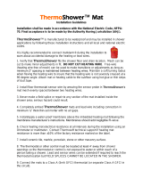
7. Never begin the mat in a shower. The connection between
the power lead and the heating wire must be fully
embedded in mortar and located at least 1' (304.8 mm)
away from shower openings and other areas normally
exposed to water.
8. Mat controls must be located at least 4' away from shower
openings. Controls cannot be exposed to water or touched
by a person while in the shower area.
9. All grout seams should be sealed after the mortar and
grout has completely cured.
10. As an option, consider installing a dedicated mat in the
shower area, separate from the rest of the floor. This will
increase control options, allowing less floor to be warmed
when the shower is not required. It will also allow for
better isolation of the shower area in the off-chance a
problem occurs.
STEP 4.10
Take photographs of the mat installation. This can be very
useful later during remodel work to help avoid possible
wire damage. Keep the photos with this installation
manual and provide to end user upon completion.
Heating Wire
Factory Splice
Shower Curb
Tile
Thinset Mortar
Notches in Shower Curb
(Minimum 1" wide, to avoid sharp
bends in cable and ensure cable is
fully embedded in mortar.)
Locate power lead and factory connection to heating wire at least
1' outside the shower area.
Phase 5: Floor Coverings
It is recommended to consult with professional flooring
installers to make sure proper materials are used and
proper installation techniques are followed. Please note,
this installation manual is not a structural or a floor covering
installation manual and is intended only for general guidance
as it applies to the SunTouch Mat product.
When installing tile or stone, the Tile Council of North
America (TCNA) guidelines, National Tile Contractors
Association (NTCA), or ANSI specifications should be followed
as a minimum standard.
A polymer-modified thin-set cement-based mortar and
grout is recommended instead of water-based multi-purpose
materials when installing a radiant product.
Do not use solvent based adhesives or pre-mix mortars
because they are not as heat resistant.
Select the proper size trowel for the installation of tile or
stone. We recommend a minimum 3/8" x 1/4" trowel. This
trowel works well for most ceramic tile. A thicker thin-set
can be used if required. Select the thin-set thickness in
accordance with the floor covering requirements.
For additional information on tile installation, please contact
TCNA at 864-646-8453 or visit their web site at www.tileusa.
com.
When installing floor coverings other than tile or stone, follow
industry and/or manufacturer’s recommendations. Ensure
the mat is first covered with a layer of self-leveling cement
based mortar, letting it cure fully before applying any surface
underlayment, floating wood or laminate flooring, carpet,
etc. The combined R-values of all floor coverings over the
mat should not exceed R-3. Higher R-values will diminish
performance. Consult the floor covering manufacturer to
verify compatibility with radiant electric heat. Also, make sure
nails, screws, or other fasteners do not penetrate the floor in
the mat area. The wire can easily be damaged by fasteners
penetrating the floor.
All floor coverings must be in direct contact with the cement-
based mortar encasing the mat. Do not elevate the floor
above the mortar mass. Do not install 2" x 4" wooden nailers
(sleepers) on top of a slab for the purpose of attaching
hardwood. Any air gap between the heating mat and the
finished floor covering will drastically reduce the overall
output of the heated floor.
Care should be taken when laying area rugs, throw rugs, and
other surface products on the floor. Most products are okay
to use, but if in doubt, consult the product manufacturer for
compatibility. Do not use rubber backed products that may
degrade or very heavy rugs that will trap heat. Be careful not
to place a rug over the area where the sensor tip was placed,
causing false thermostat readings.
When placing furniture make sure an air clearance of at least
1-1/2" is available. Furniture able to trap heat can damage the
heating system, the flooring, and the furniture over time.
Use a digital multi-meter to measure the resistance
between the conductors of the power leads again. Record
these resistances in Table 4 under After floor coverings
are installed”.
14
SunTouch Mat Do It Yourself Manual
!
CAUTION
Never bang a trowel on the heating
wire to remove excess mortar from
the trowel. This could damage the
heating wire.
DOUBLEPLYWOOD OVER FRAME FLOOR
Tile/stone or laminate flooring
Tile/stone or
laminate flooring
Mat
Plywood
Main Plywood Subfloor
Latex-Portland cement
mortar bond coat
Insulation (per International
Residential Code, Chapter 11)
Concrete slab with
rewire or rebar
Crack isolation membrane
Mat
Thin-set or self-leveling
mortar bed
Insulation (per International
Residential Code, Chapter 11)
Insulation (per International
Residential Code, Chapter 11)
Cement backerboard,
thick-set, or self-leveling
mortar bed
Mat
Thin-set
THIN-SET OVER SLAB ON GRADE
CEMENT BACKERBOARD OVER FRAME FLOOR
Type of Construction
Mortar Applications:
Thin-set and thick-set (self-leveling) mortar
applications are illustrated to the right.
a. If a backer board or plywood sheeting is
used to strengthen the floor, or if the mat
will be placed directly onto the slab, install
mat in the thin-set mortar bond coat
above these materials.
b. If a thicker mortar bed, or self-leveling
concrete, is used to strengthen the floor,
mat can be installed in either the mortar
bed (dry-set) or in the mortar bond coat
directly below the tile or stone.
SunTouch Mat is generally installed above the
self-leveling mortar in a thin-set bond coat.
Use plastic lath instead of the typical metal
lath when installing in a self-leveling layer.
Self-leveling Mortar Applications:
These are appropriate applications if
installing engineered wood, vinyl, laminate,
or carpet floor coverings. Attach the mat to
the subfloor or slab, then pour self-leveling
mortar 1/4" to 1/2" thick according to
manufacturers specifications. Install floor
covering after the mortar has cured.
Special Precautions
Isolation Membrane: Install the mat above
the membrane, whenever possible,
unless recommended otherwise by the
membrane manufacturer.
Insulation: Insulation dramatically enhances
the performance and efficiency of floor-
warming systems. Do not install rigid
insulation directly above or below backer
board or mortar.
Mosaic Tile: When installing mosaic tile, it
is recommended to apply a two-step
process. First, embed the mat in a thin self-
level mortar bed (1/4"–3/8"), then thin-
set the mosaic tile according to typical
practice.
Expansion Joints: Do not install heating mats
through an expansion joint. Install mats
right up to the joint, if necessary, but not
through the joint.
SunTouch Mat Do It Yourself Manual
15
Phase 6: Control Installation
STEP 6.1:
Install the Controls
If it has not already been done, install an electrical box for the
SunStat. Do not forget to attach a single-gang mud-ring to
mount the SunStat if a 4" square box was used. See Phase 3 for
details.
STEP 6.2
Refer to the wiring diagrams in the Appendix of this manual for
typical configurations.
STEP 6.3
Read and follow the instructions included with the SunStat
thermostat for complete connection instructions, requirements,
and mounting.
STEP 6.4
Make any final connections to the circuit breaker or branch
circuit source
STEP 6.5:
System Start Up
After all controls are installed, do not energize the system,
except to briefly test operation of all components (no longer
than 10 minutes). Do not put the system into full operation
until the tile or flooring installer verifies all cement
materials are fully cured (typically two to four weeks). See
mortar manufacturer’s instructions for recommended curing
time.
NOTE: Most laminate and wood floor manufacturers specify
their flooring should not be subjected to temperatures
over 82 to 84F (27 to 28C). Check with the flooring
dealer or manufacturer and set the thermostat
appropriately.
Refer to the installation sheets provided with the controls for
proper setting. The system should now operate as designed.
Please leave this instruction manual, SunStat instructions, and
copies of photos of the installed heating system with the end
user.
Bottom plate
cut-outs
Power
supply
Sensor installed in floor
(equal distance between two heating wires)
electrical box
Single-gang Mud Ring
(if required)
Electrical conduit
Sensor wire
Mat power lead
Mat Mesh
Thin-set, thick-set, thin-
slab, or self-leveling
mortar bed
Tile, stone, or laminate
floor covering
SunStat Thermostat
Tape
Heating Wire
General layout of the SunTouch Mat installation
16
SunTouch Mat Do It Yourself Manual
Appendix
90° or Flip Turn
Roll-over Turn
180° or Back-to-Back Turn
Fill-in Technique
Types of turns
Step-by-step layout for a typical bathroom
1. 2.
3.
4. 5.
6.
7. 8.
SunTouch Mat Do It Yourself Manual
17
Toilet
Shower
Shower
Bath Tub
Bath Tub
Closet
Bathroom layout 1: One 30" x 20' mat
Bathroom layout 2: One 30" x 12' mat, one 30" x 6' mat, and one 30" x 32' mat.
Vanity
Vanity
Doorway
Doorway
Control
Control
Control
One 30" x 12' mat
One 30" x 6' mat
One 30"x 32' mat
Toilet
Install 4"–6" from walls.
Install mats right up to the face of the
cabinet. The heat only conducts about
1-1/2" from the wire.
Install mats 4"–6" away from wax ring
(18"–20") from back wall.
Fill in triangular areas by
removing wire from mat and
securing with hot glue..
Do not begin the mat inside the shower area. The
controls should NEVER be installed in the shower
area, or where anyone in the shower could touch
the controls. Install the controls a minimum of 4'
away from the shower area.
Never install the mat
in shower walls (or
any other walls).
Locate power lead and connection
to heating element outside the
shower area.
Toilet
IMPORTANT
See phase 4 for complete details
and Cautions. This application into
a shower area must be verified by
the local inspector or the authority
having jurisdiction.
Locate power lead and factory connection to
heating wire at least 1' outside the shower area.
Heating Wire
Factory
Splice
Shower Curb
Tile
Thin-set Mortar
Notches in Shower Curb
(Minimum 1" wide, to avoid sharp
bends in cable and ensure cable is
fully embedded in mortar.)
18
SunTouch Mat Do It Yourself Manual
Front Entryway
Sink
Small bath layout 2: One 30" x 10' mat
Doorway
Doorway
Bath Tub
Vanity
Small bath layout 1: One 30" x 6' mat
Front entryway layout: Two 30" x 10' mats, one 30" x 6' mat
Control
Install mats right up to the
face of the vanity. The heat
transfers only about 1-1/2"
from the wire.
Control
Bath Tub
Control
SunTouch Mat Do It Yourself Manual
19
Ground
Black
Black
Black
White
White
White
Line 1
Load 1
Load 2
Line 2
120 or 240VAC
Sensor Wire
(no polarity)
Mat
(maximum 15 amps)
120/240 VAC
SunStat
Two or more
Mats
(maximum 15 amps)
Ground
Black
Black
Black
White
White
White
Line 1
Load 1
Load 2
Line 2
Sensor Wire
(no polarity)
120/240 VAC
SunStat
120 or 240VAC
Ground
Black
Black
Black
White
White
White
Line 1
Load 1
Load 2
Line 2
120 or 240VAC
Sensor Wire
(no polarity)
Mat
(maximum 15 amps)
120/240 VAC
SunStat
Two or more
Mats
(maximum 15 amps)
Ground
Black
Black
Black
White
White
White
Line 1
Load 1
Load 2
Line 2
Sensor Wire
(no polarity)
120/240 VAC
SunStat
120 or 240VAC
120/240VAC Control Wiring Diagrams
Typical Wiring for multiple
mats with SunStat Control
(120/240VAC)
20-amp circuit.
Note: Installation must be performed by qualified persons, in
accordance with local codes, ANSI/NFPA 70 (NEC Article
424) and CEC Part 1 Section 62 where applicable.
!
CAUTION
Make sure 120 VAC is supplied
to 120 VAC mats and 240 VAC
is supplied to 240 VAC mats.
Otherwise, dangerous overheating
and possible fire hazard can result.
Typical Wiring for one
mat with SunStat Control
(120/240VAC)
20-amp circuit.
20
SunTouch Mat Do It Yourself Manual
Connecting Multiple Mats
NOTE: The SunStat is not shown in these diagrams in order to simplify them. These diagrams are given only as examples of
how to properly connect multiple mats. Care must be taken not to overfill a box. Be sure to use wire nuts that are the
correct size for the connections being made. Follow all codes for wiring. If in doubt, consult an electrician.
Illustration showing how to connect three
mats at the thermostat control electrical
box.
Illustration showing how to connect multiple
mats from multiple junction boxes at one
thermostat control electrical box.
Thermostat
L1 = White
G = Copper
L2 = Black
L1 = Red
G = Copper
L2 = Black
  • Page 1 1
  • Page 2 2
  • Page 3 3
  • Page 4 4
  • Page 5 5
  • Page 6 6
  • Page 7 7
  • Page 8 8
  • Page 9 9
  • Page 10 10
  • Page 11 11
  • Page 12 12
  • Page 13 13
  • Page 14 14
  • Page 15 15
  • Page 16 16
  • Page 17 17
  • Page 18 18
  • Page 19 19
  • Page 20 20
  • Page 21 21
  • Page 22 22
  • Page 23 23
  • Page 24 24

SunTouch 24004830R User manual

Type
User manual

Ask a question and I''ll find the answer in the document

Finding information in a document is now easier with AI