Page is loading ...

INSTALLATION MANUAL
888-432-8932
www.suntouch.com/diy
Please be aware local codes may require this product and/or the thermostatic control to be installed or connected by an electrician.
Please leave this manual with the end user.
Do It Yourself
FLOOR WARMING
Heating Wire

Table of Contents
Phase 1: Design the System .................................3
Phase 2: Preparation......................................... 4
Cautions ................................................ 4
Tips .....................................................5
Items Needed ........................................... 5
Phase 3: Inspect the Cable and Sensor ..................... 5
Cable and Sensor Resistance Log......................... 6
Phase 4: Electrical Rough-in.................................7
New Construction ....................................... 7
Existing Construction .................................... 7
Phase 5: Install the Cable.................................... 8
Getting Started .......................................... 8
General Installation ...................................... 9
Other Installations ......................................10
Final Steps..............................................11
Phase 6: Finish Wiring ......................................12
New Construction ......................................12
Existing Construction ...................................12
Phase 7: Install the Control.................................13
Phase 8: Install the Floor Coverings .......................13
Phase 9: Install Insulation ..................................13
Phase 10: System Operation ...............................13
Troubleshooting Guide .....................................14
Appendix 1: Types of Construction .......................15
Appendix 2: Typical Electrical Wiring Diagrams .........17
Appendix 3: Connecting Multiple Cables ................19
Appendix 4: Connecting the LoudMouth
™
................20
Appendix 5: Sample Layouts..............................21
Installation Facts
Time to install
An average size bathroom should take
about two hours to install the cables and
about four hours to install the electrical box,
control, and power supply.
Skill level
This product may be secured in place by an
average do-it-yourself person or qualified
installer. However, electrical wiring is required
from a circuit breaker or other electrical circuit
to the control, so it is recommended that an
electrician perform these installation steps.
Please be aware that local codes may require
this product and/or the control to be installed
by an electrician. Prior to installation you are
required to consult your local codes in order
to understand what is acceptable in your area.
To the extent this information is not consistent
with local codes, the local codes should be
followed.
Expected floor temperature
The floor temperature attainable is depen-
dent on how well the floor is insulated, the
temperature of the floor before start up, and
in the case of uninsulated slab applications,
the thermal drain of the underlying materials.
These are the three most common installations:
1. Wood subfloor: With the cable installed
on a well-insulated wood subfloor, and thin-
set mortar and tile on top, most floors can be
heated up to 20°F (11°C) warmer than they
would otherwise be.
2. Insulated concrete slab: With the
cables installed on an insulated concrete slab,
and thin-set mortar and tile on top, most floors
can be heated up to 15°F (8.3°C) warmer than
they would otherwise be.
3. Uninsulated concrete slab: With the
cables installed on an uninsulated concrete
slab, and thin-set mortar and tile on top, most
floors can be heated up to 10°–15°F (5.6 to
8.3°C) warmer than they would otherwise be.
Please consult a designer or the factory
if questions remain about the surface
temperature that can be expected from the
cables in any particular construction. Please
see “Phase 9”: Install Insulation” on page 13.
SunTouch Heating Wire
Heating Wire is a simple, economical way to warm any
floor, and provide years of lasting comfort. This instruc-
tion manual provides complete details, suggestions,
and safety precautions for installing this floor-warming
system.
Fasten the cables to the floor. Then, depending on the
floor coverings to be used, put down a layer of thin-set,
thick-set, or self-leveling mortar on top of the cables.
Finally, install the floor coverings. It’s that simple!
2
SunTouch Heating Wire - Do It Yourself Manual
Specifications:
SunTouch Heating Wire is a complete heating cable consisting of a series resistance heating cable and single
power lead for easy single-point connection. The heating cable cannot be cut to fit.
Voltages: 120, 240 VAC, 1-phase
Watts: 10.3 W/sqft (35 Btu/h/sqft) when spaced 3.5 inches on center, up to 14.4 W/sqft (49 Btu/h/sqft) when
spaced 2.5 inches on center. (see Table 1)
Maximum heater current: 11 amps
Maximum circuit load: 16 amps
Maximum circuit protection: 20 amps breaker
GFCI: (Ground Fault Circuit Protection) required for each circuit (included in the SunStat control)
Listing: UL Listed for U.S. and Canada under UL 1673 and CAN/CSA C22.2 No. 130-03, File No. E185866
Application: (-X) - (see UL Label on product) For indoor floor heating application only
(-W) - (see UL Label on product) Wet Rated for use in wet locations per this manual
Embedded in polymer-modified cement based mortar (see Appendix 1)
Minimum bend radius: 1 inch
Maximum exposure temperature: (continuous and storage) 194ºF (90ºC)
Minimum installation temperature: 50ºF (10ºC)

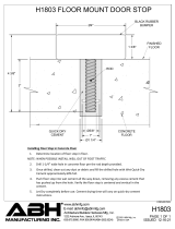
3” spacing
4” spacing
NEVER use less than 2.5”
spacing.
NEVER exceed 3.5” spacing.
STEP 1.1
Phase 1: Design the System
Heating Wire should be installed in all interior floor areas that are to be
warmed. It cannot be used for exterior applications, snow melting, or in ceil-
ings. In some applications, it can be used to heat the room as well, but in gen-
eral it is not designed for this purpose (heat-loss calculations must be made
to determine if enough heat will be provided to match the heat loss of the
room).
STEP 1.1 Make a sketch of the room. Measure the total square footage of
floor area to be warmed (measurements should be made all the way to the
edge of walls, cabinets, tub, etc., for now). Keep in mind the following:
• Heatwillnotradiatebeyondabout2”oneithersideofthecable,
therefore consistent coverage is important.
• Thecablescanbeinstalledinpermanentbenchseatswithtileorstone
coverings.
• Type (-W) cables only (see UL Label on product) may be installed into
shower floors and bench seats. However, do not install them into the
walls. Consider installing a dedicated cable in the shower area separate
from the rest of the bath floor. In case there is ever a problem with the
shower installation, this cable could be disconnected without loss of heat
to the rest of the floor. Acceptance of this shower application must be
verified by the local inspector or authority having jurisdiction. See
Step 5.20 and Appendix 5 for details and precautions.
• Donotinstallthecablesunderneathcabinetsorfixturesorinsidea
wall. Excessive heat will build up and cause damage.
• Donotrunthecablesintosmallclosetsorotherconfinedareaswhere
excessive heat will build up.
• Do install cable within about 1-1/2” to 2” from a counter or vanity in the
kick-space to ensure warmth in this area.
• Donotinstallthecablescloserthan6”fromtoiletringstoavoid
possible melting of wax rings.
• Inopenareas,likesunroomsordiningrooms,considerinstallingthe
cables 6” to 12” away from the perimeter of the room since people
rarely stand this close to walls.
STEP 1.2 Select the cable spacing. Below are typical spacings for various
types of rooms. This spacing can vary depending on the insulation of the floor
and room, and the desired effect. Never space cables closer than 2.5” apart;
this will cause a very hot area and may cause damage.
Typical uses:
• 2.5”spacing: Bathrooms, kitchens, living areas, and sunroom floors.
(NOTE: Insulation is always recommended due to high heat
losses in these areas. Performance is never guaranteed due to
construction and climate differences in these applications.)
• 3.5”spacing: Hallways, entryways, and large areas with low heat loss.
STEP 1.3 Multiply the square footage measured in Step 1.1 by 0.90 to allow
for 3” spacing around the edges of the floor area. Use this resulting square
footage to select the appropriate cable from the tables on page 4.
Remember:
• Donotplaceover15ampsat120VAC(1800watts)or15amps
(3600 watts) at 240 VAC through a control.
• Selecteither120VACor240VACdependingonthepoweravailable.
DONOTmixvoltagesonthesamesystemifmorethanonecableis
to be installed to cover an area.
• Loadnomorethan12amps(1440watts)ona15-ampcircuitbreaker,
or 16 amps (1920 watts) on a 20-amp circuit breaker.
• Ifyouhaveanareathatrequiresmorethan15ampsofcablestobecon-
trolled by one thermostat, a separate SunStat must be used to control the
additional load.
• SeetheWiringDiagramsinAppendix2forhelp.
If the exact size of cable calculated is not found in the spool selection tables
on page 4, it may be necessary to adjust the warming area(s) or select the next
smaller spool size. Remember, the cable must never be cut shorter to fit,
and must be embedded completely in mortar in the floor. Be careful not
to select a spool that is too large.
STEP 1.4 The strap supplied with the cable is used to secure the cable to the
floor. One box contains 25 ft. of strap, enough to prepare about
50 sq. ft. of floor at 4-ft. spacing. Strap is usually spaced every 3 to 4 ft.
Use of methods to secure the cable other than those described in this
Manual voids the Warranty and are not allowed unless authorized by the
manufacturerinwriting.Donotusenails,staples,orsimilar.
3.5” spacing
SunTouch Heating Wire - Do It Yourself Manual
3

Table 1: 120 VAC Heating Wire Kits*
Model
Number
Total sq. ft
2.5” Spacing
14.4 watts/sq. ft.
Total sq. ft
3” Spacing
12 watts/sq. ft.
Total sq. ft
3.5” Spacing
10.3 watts/sq. ft.
Length
(ft)
Amp.
Draw
Resistance
(ohms)
CO120020R 17 20 23 78 2 64-79
CO120030R 25 30 35 117 3 37-46
CO120040R 33 40 47 156 4 27-35
CO120050R 41 50 58 195 5 21-26
CO120060R 50 60 70 234 6 20-26
CO120070R 58 70 82 273 7 16-21
Table 2: 240 VAC Heating Wire Kits*
CO240040R 33 40 47 156 2 128-157
CO240060R 50 60 70 234 3 74-91
CO240080R 66 80 94 312 4 55-69
CO240100R 83 100 117 390 5 41-52
CO240120R 100 120 140 468 6 40-51
CO240140R 116 140 164 546 7 33-41
Phase 2: Preparation
CAUTION!
As with any electrical product, care should be taken to guard against the
potential risks of fire, electric shock, and injury to persons. The following
cautions must be observed:
NEVER cut the heating cable. The 10-ft. power lead may be cut shorter if
necessary, but never removed from the heating cable.
NEVER use nails, staples, or similar to fasten the heating cable to the
floor.
NEVER bang a trowel or other tool on the cable. Be careful not to nick,
cut, or pinch the cable causing it to be damaged.
NEVER install the cables under cabinets or other built-ins. Excessive heat
will build up under these items and cause damage.
NEVER install the cable in any walls, over walls or partitions that extend
to the ceiling, or in closets.
NEVER extend the heating portion of the cable beyond the room or area
in which it originates.
NEVER attempt to repair a damaged cable. Contact the factory for assis-
tance.
NEVERoverlapheatingcables.Dangerousoverheatingcanoccur.
NEVER allow a power lead or sensor wire to cross a heating cable; dam-
age could result.
NEVER embed the cables in adhesives intended for laminate or vinyl
flooring. Cables must be completely embedded in cement-based
polymer-modified mortar.
NEVERapplythewrongvoltagetoacable.Damagecanresult.
NEVER use less than 2.5” spacing.
ALWAYS completely embed the heating wire and factory splice
in mortar.
ALWAYS maintain a minimum of 2.5” spacing between cables.
ALWAYS use copper only as supply conductors to the control and the
cable.Donotusealuminum.
ALWAYS test the cable resistances and record them in the Cable and
Sensor Resistance Log (page 6).
ALWAYS pay close attention to voltage and amperage requirements of
the circuit breaker, control, and the cable system. For instance, do not
supply 240 VAC to 120 VAC controls and cables.
ALWAYS make sure all electrical work is done in accordance with local
building codes, the National Electrical Code (NEC), especially Article
424, Part IX, and Section 62 of the Canadian Electrical Code (CEC) Part I.
NEVER bang a trowel or other
tool on the heating cable.
NO!
Always completely embed the
factory splice and all heating wire
in mortar. NEVER bend the splice
or place any part of it in the wall
or through the floor.
NEVER use less than 2.5” spacing.
NO!
ALWAYS!
* Kits include cable strap, double sided tape, and manual
* Kits include cable strap, double sided tape, and manual
ALWAYS
4
SunTouch Heating Wire - Do It Yourself Manual

Some Tips
Trowel. Use a plastic trowel to reduce the possibility of cable damage.
Insulation. The better insulation that is provided, the more efficiently
the system operates, and the better the floor is heated. Concrete slab sur-
faces offer the most thermal drain and should be insulated before applying
the cables, if at all possible. See “Phase 9: Install Insulation” as well as the
cross sections in Appendix 1.
Controls. The SunStat control will provide direct floor-warming control
for better comfort.
Mortars. Self-leveling mortars are becoming more popular to use
because of their ease of application over the cables. If laying tile, another
layer of thin-set will need to be applied in order to lay the tile. Always
usepolymer-modifiedcement-basedmortar.Donotusesolvent-based
adhesives or pre-mixes because they are not as heat resistant.
LoudMouth
™
(sold separately) The LoudMouth sounds an alarm if
damage occurs to the cable during installation. The LoudMouth stays
connected to the power leads throughout cable and tile installation.
Items Needed
SunTouch Heating Wire, Cable Strap, and control all available from
retailer. Other items may be obtained at a local hardware store.
Materials:
• SunTouchHeatingWiresystem
• CableStrap
• SunStatcontrolwithfloorsensor
• 20-ampcircuitbreaker(singlefor120-VACanddualfor240-VAC
systems)
• Electricalbox(extradeep)forthecontrol;single-gang(notagangable
type) or 4”-square deep box with a single-gang “mud ring” cover
• 4”junctionboxwithacover,ifneeded
• Cableclampsforjunctionbox(fornewconstruction)
• Flexibleorrigidconduit(fornewconstruction)
• 12-gaugeor14-gaugeelectricalwiringcable(consultlocalcode)
• Wirenutsifusingajunctionbox
• Nailplate
• Polymer-modifiedcementbasedmortar
Tools:
• Digitalmulti-meter[forohmstesting;mustreadupto20,000ohms(Ω)
to measure sensor]
• Drillwith1/2”bit
• Hammerandchisel
• Wirestrippers
• Phillipsscrewdriver
• Fishtape(forexistingconstruction)
• Holesaw(forexistingconstruction)
• Trowel(plasticpreferred)with3/8”notches(orgreater)
Phase 3: Inspect the Cable and Sensor
STEP 3.1 Take the cable out of the box and inspect it to make sure there
is no visible damage. There are shielded leads coming out of the spool
of cable called the “power leads” (they are simply power supply cables
that do not heat). The power leads are approximately 10 ft. long and will
connect the heating cable to the control for power.
STEP 3.2 Record the product information. There is a factory-applied
nameplatelabelonthepowerleads.Donotremovethislabel.Recordthe
cable serial number, model number, voltage, and cable resistance range in
the Cable and Sensor Resistance Log (page 6). If installing more than one
cable, do this for each of them.
STEP 3.1
STEP 3.2
SunTouch Heating Wire - Do It Yourself Manual
5

IMPORTANT! To retain the Limited Warranty, the following measure-
ments must be recorded, and all steps of this manual followed.
STEP 3.3 Take resistance readings of the cable and floor sensor to
make sure they are not damaged. It is very important that this be done
throughout the entire installation process. Use a quality digital ohm-
meterormultimeter[abletomeasureupto20,000ohms(Ω)] to make
these measurements. Analog meters (that use a moving needle) are
not accurate for this product and should not be used.
Take resistance readings (1) before beginning the installation,
(2) after the cable and sensor are fastened to the floor, and (3) after floor
coverings are installed. Checking these measurements frequently
during finished floor installation is strongly recommended in order to
avoid burying a damaged cable.
Check for Breaks
Measure resistance between the black and white cable leads (black and
blue leads for 240-VAC cables) and record this in the chart below. This
measurement should be within the cable resistance range shown on the
nameplate label. Measure between the lead wires of the floor sensor.
This resistance varies according to the temperature sensed in the tip.
The sensor resistance table at left provides approximate values for com-
parison. A cut or break in the wire is indicated by a resistance of “infinite”
ohms (no continuity).
Check for Short-Circuits
Measure resistance between the black and ground leads and between
the white and ground leads (blue and ground leads for 240-VAC cables)
and record this value below. These measurements should be “infinite”
ohms (no continuity). A cut or pinch in the wire is typically indicated by a
resistance value less than the cable resistance range.
STEP 3.3
CABLE 1 CABLE 2 CABLE 3
Cable serial number
Cable model
Cable voltage
Factory cable resistance range
OUT OF THE BOX BEFORE INSTALLATION (ohms)
Cable black to white
(black to blue for 240VAC)
Cable black to ground
Cable white to ground
(blue to ground for 240VAC)
Sensor wire
AFTER CABLE AND SENSOR ARE FASTENED TO FLOOR (ohms)
Cable black to white
(black to blue for 240VAC)
Cable black to ground
Cable white to ground
(blue to ground for 240VAC)
Sensor wire
AFTER FLOOR COVERINGS ARE INSTALLED (ohms)
Cable black to white
(black to blue for 240VAC)
Cable black to ground
Cable white to ground
(blue to ground for 240VAC)
Sensor wire
RETAIN THIS LOG TO RETAIN THE WARRANTY! DO NOT DISCARD!
Cable and Sensor Resistance Log
Floor Sensor Resistance Values
Temperature Typical Values
55°F (13°C) 17,000 ohms
65°F (18°C) 13,000 ohms
75°F (24°C) 10,000 ohms
85°F (29°C) 8,000 ohms
6
SunTouch Heating Wire - Do It Yourself Manual

STEP 4.2
Install an extra-deep single-gang
box if connecting one or two cables
to the control. Use a 4”-square deep
box with a single-gang mud ring
cover if connecting three cables,
because the extra room is needed
for the wire, wire nuts, and control.
STEP 4.5
Phase 4: Electrical Rough-in
See wiring diagrams in Appendix 2 for different voltages and applications.
For additional help, call 800-363-1501.
New Construction (see below for existing construction)
OVERVIEW We recommend the floor-warming system be installed on a
dedicated circuit coming directly from the circuit breaker panel. Follow
all National Electric Code (NEC), Canadian Electrical Code (CEC), and other
local electrical code requirements when installing this system. Work
should be done with great care and with the power turned off to the
circuit being worked on.
STEP 4.1 Install a maximum 20-amp circuit breaker(s) into the breaker
panel, depending on the load of the system. Use a 120-VAC single-pole
breaker for a 120-VAC system. Use a 240-VAC double-pole breaker for a
240-VAC system.
STEP 4.2 Install an electrical box for the control. If installing one to two
cables, use an extra-deep single-gang box to allow plenty of room for the
wiring. Use a 4”-square box if installing three cables. The box can be locat-
ed almost anywhere that is well ventilated. However, the best place is in
the same room as the cable, typically about 60” above the floor, and within
reach of the power lead wires of the cable. If installing more than three
cables, it will be necessary to connect their power leads in a junction box
first (see Step 4.4) to keep from overfilling the control electrical box. Then
route one power supply from this junction box to the control box.
STEP 4.3 Following code, feed 14- or 12-gauge NM type electrical wiring
from the circuit breaker panel to the control electrical box. Leave about
6”–8” of extra wire extended from the box to work with.
STEP 4.4 If the control box must be mounted in a location that is too far
to reach with the power lead wires, it will be necessary to mount a junction
box where the lead wires can be terminated. Use a standard junction box
with a cover, mounting it below the floor, in the attic, or in another easily
accessible location. It must remain easily accessible and not located behind
a wall, cabinet, or similar obstruction. Then use 14- or 12-gauge NM type
or other accepted electrical wiring to connect from the junction box to the
control box.
STEP 4.5 Drilltwo1/2”holesinthebaseplatedirectlybelowthecontrol
electrical box. Then, as close to the floor surface as possible, drill two
horizontal holes, intersecting the top holes.
STEP 4.6 If conduit is required by local electrical code, cut a length of
1/2” to 3/4” electrical conduit to run from the control box down to the
baseplate. At the baseplate it may be necessary to chisel out more of the
wood to make it easier to feed the wires up through the conduit.
STEP 4.7 Mark the circuit breaker in the panel which feeds the system
with “Floor warming/bath” or similar description.
Existing Construction
OVERVIEW It is recommended that the system be installed on a separate,
dedicated circuit coming directly from the breaker panel. In existing con-
struction, however, it may be difficult to do this depending on the location
of wiring and the breaker panel. Tapping off an existing circuit may be pos-
sible, but only if there is enough load capacity to handle both the system
and any additional loads that may be placed on the circuit. Keep in mind
that typical hair dryers can pull up to 10 amps (1200 watts) of load.
Follow all NEC, CEC, and other local electrical code requirements when
installing this system. Work should be done with great care and with the
power turned off to the circuit being worked on.
SunTouch Heating Wire - Do It Yourself Manual
7

STEP 4.10
STEP 4.12
STEP 5.3
STEP 4.11
STEP 4.9
STEP 4.8 Install a maximum 20-amp circuit breaker(s) into the breaker
panel, depending on the load of the system. Use a 120-VAC single-pole
breaker for a 120-VAC system. Use a 240-VAC double-pole breaker for a
240-VAC system.
STEP 4.9 Cut an opening in the wall for the control electrical box.
If installing one to two cables, use an extra-deep single-gang box to
allow plenty of room for the wiring. Use a 4”-square box if installing
three cables. The box can be located almost anywhere that is well venti-
lated. However, the best place is in the same room as the cable, typical-
ly about 60” above the floor, and within reach of the power lead wires
of the cable. If installing more than three cables, it will be necessary to
connect their power leads in a junction box first (see Step 4.11) to keep
from overfilling the control box. Then route one power supply from this
junction box to the control box.
STEP 4.10 Following code, feed 14- or 12-gauge NM type electrical
wiring from the circuit breaker panel to the control electrical box
opening. Leave about 6”–8” of extra wire extended from the opening.
STEP 4.11 If the control box must be mounted in a location that is
too far to reach with the power lead wires, it will also be necessary to
mount a junction box where the lead wires can terminate. Use a
standard junction box with a cover, mounting it below the floor, in
the attic, or in another easily accessible location. It must remain easily
accessible and not located behind a cabinet or similar obstruction. Then
use 14- or 12-gauge NM type or other accepted electrical wiring to con-
nect from the junction box to the control electrical box.
STEP 4.12 At the floor level below the control box, cut a 2”x 2”-wide
piece from the wall surface. Use a wood chisel to notch out a channel in
the baseplate to make it easier to route the wires up the wall.
STEP 4.13 Mark the circuit breaker in the panel which feeds the
system with “Floor warming/bath” or similar.
Phase 5: Install the Cables
Getting Started
IMPORTANT! Refer to Phase 8 and Appendix 1 to make sure the
floor is properly prepared for installation of the cable(s), especially
the use of reinforcement, leveling, and insulation on concrete slab.
STEP 5.1 Use the sketch and design considerations made earlier in
Phase1tobeginlayingthecables.Donotinstallthecablescloser
than about 6” from wax toilet rings and plumbing to keep from over-
heating these items.
STEP 5.2 Make sure to space the cables to provide the warmth
desired.
WARNING: This heating cable CANNOT be cut shorter to fit!
Do not overlap or cross over heating cable on itself. Do not
space heating cables less than 2.5” apart. Failure to do so may
result in damage to the product and dangerous overheating.
STEP 5.3 If this is new construction, draw lines on the floor or use
templates to outline the area of any cabinets, fixtures, or future walls
that will be placed in the room. NEVER install the cables under cabi-
nets, fixtures, or walls. Excess heat may build up under these items and
cause damage.
STEP 5.4Decidewhichdirectionthecableswillrunonthefloorfor
the easiest coverage. Refer to the sample layouts in this manual for
assistance.Dependingontheshape
of the area, it may help to think of it
in terms of several smaller areas.
NEVER use less than 2.5” spacing.
8
SunTouch Heating Wire - Do It Yourself Manual

General Installation
STEP 5.5 Measure about 3” from the wall for the strap. If the design called
for 6”–12” away from the wall, install the strap at that distance. In counter
or vanity kick-spaces, install the strap so the cable will be 1-1/2” to 2” away
from the vanity.
STEP 5.6 Cut the strap to fit the length of the first area.
STEP 5.7 Secure the strap to the floor using double-sided tape, or using
hot glue.
STEP 5.8 For added securement, on concrete floors, use a hammer drill
to set holes into the concrete. Secure the strap every 6”–10” by driving
anchors into the holes.
STEP 5.9 Cut another piece of strap for the other end of the area and
secure 3” from the wall(s) or other obstruction(s).
STEP 5.10 Unreel the power leads of
the cable up to the factory splice. Let
the coil of power leads sit on the floor
for now. Beyond the factory splice is
the heating cable itself. Factory splice
must be installed in the mortar bed.
CAUTION: Completely embed the
factory splices and heating cable in
the mortar, and never bend the fac-
tory splices. NEVER allow any part of
the splice or heating cable to enter a
wall or drop through the subfloor.
STEP 5.11 Before installing more
strap, fill in the first section with cable.
Begin by making a “strain-relief” at the
beginning so the cable is not acciden-
tally pulled loose.
STEP 5.12 Weave the cable back and
forth across the area at the desired
spacing until the other side of the
room has been reached. Once this
area is completed, press down all the
tabs. NEVER space the cables less than
2.5” apart.
STEP 5.13 If there are additional
areas to cover with cable, cut the
lengths of strap necessary, attach
them to the floor, and begin weaving
the cable into that area.
STEP 5.8
STEP 5.5
STEP 5.6
STEP 5.9
STEP 5.11
STEP 5.10
SunTouch Heating Wire - Do It Yourself Manual
9

Other Installations
Because many different room
shapes and floor obstructions
may be encountered in any given
installation, additional layouts
are provided below to assist in
determining the best way to
complete installations in odd-
shaped areas.
Corner shower or vanity
STEP 5.14 For an angled area,
such as a corner shower, first cut
several pieces of strap a little longer
than the cable spacing being used.
STEP 5.15 Use a chalk line or pen
to mark the floor at 3” from the
edge of the shower.
STEP 5.16 Use this chalk line to
attach each piece of strap to the
floor so that the cable does not get
any closer to the corner shower
than 3”. Make sure that the cables
are spaced evenly and parallel to
one another.
STEP 5.17 Fill in the section with
cable.
Door entryway
STEP 5.18 For an entryway or
other small area where warmth
is required, begin by cutting two
lengths of strap a little shorter than
the length of the entry opening. Then secure the two straps parallel to
each other.
Bench Seat
STEP 5.19 If covering a bench seat or step area (not in a shower area),
place a single run up the riser. Use straps to secure the cable to the
seat area at the desired spacing, then install a single run down the riser.
Again, the cable on the riser and seat area MUST be fully embedded in
mortar and have approved floor coverings. Use hot glue where necessary
to secure the cable flat against the riser.
STEP 5.17
STEP 5.15
STEP 5.14
STEP 5.18
STEP 5.16
Shower area installation
This application into a shower area must be verified by the local inspector
or the authority having jurisdiction.
STEP 5.20 Type (-W) cable (see UL Label on product) may be installed
into a floor or bench seat located in a shower area. It must never be
installed into walls.
In general, the cable should be completely embedded into mortar
directly below the surface coverings of tile or stone. Other types of
coverings are not recommended. See Appendix 5 for an example of this
type installation.
Alternatively, it may be embedded in mortar beneath the waterproof
system, however performance will be reduced.
Consider installing a dedicated cable in the shower area separate from
the rest of the bath floor. In case there is ever a problem with the shower
installation, this cable could be disconnected without loss of heat to the
rest of the floor.
STEP 5.21 Make sure the power lead factory splice (the connection
between the power leads and the heating cable) is located outside the
shower area and at least 1’ away from shower openings and other similar
areas normally exposed to water. Make sure the control is located at least
4’ away from shower openings such that it cannot be exposed to water or
touched by a person in the shower area.
STEP 5.22 If the heating cable must enter the shower area over a curb,
notch the corners of the curb with a minimum 1” wide notch to ensure
the cable is not bent sharply or pinched when surface coverings are
installed.Donotdamageanywaterproofingcomponents,anddonotrun
the heating cable through a non-masonry curb, causing it to overheat.
STEP 5.23 If covering a shower floor, cut lengths of strap and secure to
thefloorwithadhesives.Donotusefastenersthatpenetrateanywater-
proofing membrane or waterproofing system. Fill in the floor area with
10
SunTouch Heating Wire - Do It Yourself Manual

Final Steps
STEP 5.27 If a second cable is to be installed in the area, all power leads must come back
to the control, or to a junction box and then to the control. NEVER run power leads across
heating cables, under baseboard areas, or other potentially damaging areas. Never join two
cables in series.
STEP 5.28 To secure long lengths of heating cable, place additional, short lengths of the
strap at 3 to 4-ft. intervals. Spray the back of the strap with a high-tack adhesive, and slide
the strap, upside down, under the cables. Turn the strap over when it is positioned and
adhere to the floor. Press the tabs down over the cables. If a spray adhesive was not used,
carefully secure these short lengths of strap to the floor without damaging the cable.
STEP 5.29 After the cable installation is completed, inspect the work. Make sure all tabs
are pressed down, cable spacings are correct, no cables cross over each other, all the cables
are undamaged, and all areas to be heated are covered with cable.
STEP 5.30 Take resistance readings of the cable again to make sure it has not been damaged
during the installation. This is very important to do. Record these readings in the Cable and
Sensor Resistance Log (page 6).
STEP 5.31 (optional) With the heating portion of the cable fully installed, it is recom-
mended that the cable be temporarily connected to the power source and allowed to heat
for several minutes. After the cables begin to feel warm to the touch, disconnect the power.
STEP 5.32 Lay cardboard, carpet, or similar material over the cables to protect them from
damage until the floor covering is installed.
cable. Around the drain leave at least 2” spacing from the edge of the flange. Make sure cable is not
placed where door hardware, handrails, or other items may mount to the floor.
STEP 5.24 If covering a bench seat in the shower, cut lengths of strap and secure to the top surface
oftheseatwithadhesives.Donotusefastenersthatpenetrateanywaterproofingmembraneor
waterproofing system. Use hot glue to secure a single run of cable up the side of the bench riser. Fill
in the seat area with cable. Then secure a single run of cable down the riser if needed.
STEP 5.25 If the cable cannot exit the shower area, the end of the cable has a waterproof splice that
may be located in the shower area, fully embedded into the mortar like the heating cable.
STEP 5.26 If any part of the heating cable entering a shower area is damaged during installation,
do not attempt to repair it. A field repair or modification of the cable may result in serious shock
hazard.
SunStat Control
Factory Splice
Thermostat
Sensor
Wire
Strap
Thin Set Mortar
Tile/Stone
SunTouch Heating Wire installed in shower floors and/or benches. See Step
5.20 and Appendix 5.
SunTouch Heating Wire - Do It Yourself Manual
11

Phase 6: Finish Wiring
STEP 6.1 Chisel a channel into the floor to lay the factory splice into. This
will ensure the splice does not create a high-spot in the floor. CAUTION:
The power lead splice MUST BE FULLY EMBEDDED IN the mortar bed and
never bend the factory splices. NEVER allow any part of the splice or
heating cable to enter a wall or drop through the subfloor.
New Construction
STEP 6.2 Feed the power leads from the cable up through the hole drilled
in the baseplate, or up into the conduit to the control electrical box
(or junction box if one was used).
STEP 6.3 Secure the power lead splice into the chiseled channels with
hot-glue.
STEP 6.4 Below the control, or wherever the floor sensor is to be located,
measure at least 1 ft. into the heated area. Mark the spot where the sensor
will be attached to the floor. Be sure to locate the sensor exactly between
two of the heating cables.
STEP 6.5 To make sure the sensor tip does not create a high spot in the
floor, chisel a channel into the floor and lay the sensor tip into the channel.
Hot glue the tip into place.
STEP 6.6Drillanotherholeinto
the baseplate, if needed, to feed
the sensor wire up to the control
box. Finish by securing a steel nail
plate over the wires to protect them
against baseboard nails later.
STEP 6.7 If it was necessary to end
a power lead at a junction box, feed
14- or 12-gauge electrical wire from
this box to the control box.
Tip: If more than one cable was
installed, label the ends of the power
leads with a brief description as to
which area they supply power. Use
tape to label them “Cable 1,” “Cable
2,” “Kitchen,” “Bath,” or similar. This
will make it easier to identify the
leads later on. Take photos of the
installation. This will provide a use-
ful record for any future needs.
Existing Construction
STEP 6.8 Use a fish tape to pull the
power leads up the wall to the con-
trol electrical box (or junction box if
one was used).
STEP 6.9 Secure the power lead
factory splice into the chisled chan-
nel with hot-glue (see photo for Step
6.3).
STEP 6.10 Below the control, or
wherever the floor sensor is to be
located, measure at least 1 ft. into the
heated area. Mark the spot where
the sensor will be attached to the floor. Be sure to locate the sensor exactly
between two of the heating cables (see photo Step 6.4). To make sure the sen-
sor tip does not create a high spot in the floor, chisel a channel into the floor
and lay the sensor tip into the channel. Hot glue the tip into place (see photo
Step 6.5).
STEP 6.11 Use a fish tape to pull the sensor up the wall to the control electri-
cal box, and finish by securing a steel nail plate over the power leads and sen-
sor wires to protect them against baseboard nails.
STEP 6.1
STEP 6.3
STEP 6.4
STEP 6.8
STEP 6.5
STEP 6.6
STEP 6.11
12
SunTouch Heating Wire - Do It Yourself Manual

STEP 6.12 If it was necessary to end a power lead at a junction box,
feed 14- or 12-gauge electrical wire from this box to the control box.
Tip: If more than one cable was installed, label the power leads with
a brief description as to which area they supply power. Use tape to label
them “Cable 1,” “Cable 2,” or “Kitchen,” “Bath,” or similar. This will make it
easier to identify the leads later on. Take photos of the installation. This
will provide a useful record for any future needs.
Phase 7: Install the Control
STEP 7.1 Read and follow the instructions that come with the SunStat
control.
STEP 7.2 Refer to the wiring diagrams in this manual for different volt-
ages and applications.
STEP 7.3 Install the electrical box for the control, if this has not already
been done. Connect the power leads from the cable (or the electrical
wiringcomingfromjunctionboxes)tothe“LOAD”sideofthecontrol.
Connect the incoming power to the “LINE” side of the control. Connect
the sensor wires to the sensor terminals on the control. Connect the
ground leads from the system to the ground wire from the incoming
power.
STEP 7.4 Install the control into its electrical box and turn the circuit
breaker on to power the system. Test the system and control for
several cycles. It should allow the heating cables to heat up correctly.
Note: Consider placing a loose tile over the sensor tip to simulate
warming the floor and allow the sensor to register this on the control.
STEP 7.5 Retain all instruction sheets and warranties.
Phase 8: Install the Floor Coverings
STEP 8.1 Make a Final Inspection of the Installation. Inspect the installa-
tion very carefully for evidence of damage or missing sensor(s).
STEP 8.2 Select Type of Construction. Choose the best thin-set, thick-
set, or self-leveling mortar method for the application. See Appendix 1
regarding final floor installation techniques. Consult with building pro-
fessionals and/or the factory if assistance is required.
STEP 8.3 Take Another Resistance Reading! After floor coverings have
been installed, take resistance readings of the cable again to make sure
it has not been inadvertently damaged. This is very important to do.
Record these readings in the Cable and Sensor Resistance Log (page 6).
Phase 9: Install Insulation
Insulate under the subfloor for better performance and efficiency
of the system. Refer to the Appendix 1 for diagrams and insulation
recommendations.
Phase 10: System Operation
After all system components are in place and floor coverings installed,
briefly test the operation of the system but do not put the system
into full operation until the mortar materials are fully cured (typically
one to four weeks). See the mortar manufacturer’s recommendations
for the specific type of mortar used.
Many manufacturers of laminate and wood flooring recommend a
maximum of about 84°F (29°C) on the floor surface. Be sure to program
the control accordingly. Consult the manufacturer regarding recom-
mended floor temperatures for the flooring being installed.
Energize the system. Operate the controls so that the system turns
on the floor-warming cable. The control will normally indicate that
power is being supplied to the cable. It will take some time for the
cable to warm up. Using a clamp-type ammeter (electricians normally
carry these), pull the control out of the wall and determine whether the
cables are pulling current, thus indicating they are working as intended.
TurnthesystemoffafterNOMOREthan10minutesofoperation.Do
not operate the system again until the floor mortar is cured. Once the
flooring is completely cured, the control can be used to operate the sys-
tem for many years to come.
STEP 7.3
STEP 7.4
SunTouch Heating Wire - Do It Yourself Manual
13

Troubleshooting Guide
If not qualified to perform electrical installations, it is strongly recommended that a qualified, licensed electrician
be hired to install the heating cables and related electrical components. If problems with the system arise, please
consult the troubleshooting guide below. Any troubleshooting work should be done with the power removed
from the circuit, unless otherwise indicated. Call 800-363-1501 for further assistance.
Problem
Cable resistance measure-
ment is outside the range
printed on the nameplate
label.
Floor does not get warm.
Floor heats continuously.
Floor temperature shows
“HI” or may show tempera-
ture over 100°F.
Control is not working
correctly.
Control is not working
at all.
GFCI conflicts and
false-trips.
Possible Cause
An analog ohmmeter (using a moving
needle) was used to take the reading.
If measurement shows an open or short
circuit, the cable has been damaged.
If measurement is just a little low or high, room
temperature has affected the resistance.
The resistance measurement could be from
more than one cable wired in series, or wired
in parallel. Either will provide false resistance
readings.
The ohmmeter may be set to the wrong
scale. For instance, the 200 K ohms scale
measures up to 200,000 ohms.
Cable has been damaged.
GFCI has tripped, indicated by a light on the
control or “GFCI TRIP”.
Incorrect voltage supplied, or mismatched
electrical components used.
Concrete slab floor.
Cables are wired in “series” or “daisy chained”
(end-to-end).
Incorrect wiring. The control was “bypassed”
when it was wired to the power supply.
Defectivecontrol.
Floor sensor is not wired properly, or is located
incorrectly.
If a programmable control, the programming
may be incorrect.
Incorrect voltage supplied, or mismatched
components used.
Floor sensor is not wired properly, or is not
working properly.
Loose connection(s) on line side and/or load
side of control.
Defectivecontrol.
No power is supplied.
Floor sensor is not wired properly, or is not
working properly.
Defectivecontrol.
More than one GFCI on the circuit.
An electric motor or a ballasted light source is
sharing the circuit with the cable(s).
Solution
Obtain a digital ohmmeter able to read 0 to 20,000 ohms and
remeasure the resistance.
Record resistances between all wires and contact the manu-
facturer.
Make the room temperature 65°–75°F, or contact the manufacturer.
Make sure resistance measurements are for only one cable at
a time. When connecting more than one cable to the control,
multiple cables must be wired in parallel (i.e., black to black,
white to white).
The ohmmeter should typically be set to the 200 ohms scale, with
the exception of cables having a rating above 200 ohms on their
nameplate label. If the resistance reading is outside the range
printed on the nameplate label, contact the manufacturer.
Measure cable resistance. Check for both “open circuit” and “short
circuit” as detailed earlier in this manual. If damaged, record
resistances between all wires and contact the manufacturer.
Check for loose wire connections. Reset the GFCI on the control
or circuit breaker. If it trips again, check for a short circuit in the
cable as detailed earlier in this manual. If cable is damaged,
record resistances between all wires and contact the manufacturer.
If cable is not damaged, replace the GFCI control. Also see “GFCI
conflicts” below.
Measure “line” voltage, 120V cables have black and white leads.
240V cables have black and blue leads.
Surface temperatures rise slowly in a slab. If, after 5 to 8 hours of
heating, the floor is not warmer to the touch, check for cable dam-
age (see “Cable has been damaged” above). Measure “load”
voltage/amperage to cable.
Multiple cables must be connected in “parallel” (or black-to-black,
white-to-white).
Make sure wiring connections are correct. Consult the wiring
diagram on the back of the control, the instructions that came
with the control, or the wiring diagrams in Appendix 2.
Return control to dealer for replacement.
Make sure only one floor sensor is connected to the control.
Also see “Sensor is loose or broken” above.
Carefully read and follow control programming instructions.
Test voltage, verify parts. See “Incorrect voltage supplied” above.
Make sure only one floor sensor is connected to the control.
Also see “Sensor is loose or broken” above.
Remove and reinstall the wire nuts at each connection. Make sure
the wire nuts are tight. Check all connections back to the breaker.
Return control to dealer for replacement.
Check circuit breaker. Measure voltage at the control. Check all
connections between breaker and control.
Make sure only one floor sensor is connected to the control.
Also see “Sensor is loose or broken” above.
Return control to dealer for replacement.
GFCI units sometimes trip when there is nothing wrong with the
equipment on the circuit, but when there is more than one GFCI.
Reroute power to avoid having more than one GFCI on the circuit.
Electric motors and other electrical devices can cause a GFCI to
false-trip. Run a dedicated circuit to the floor-warming system.
14
SunTouch Heating Wire - Do It Yourself Manual

Tile/stone or laminate flooring
Tile/stone or laminate flooring
Heating cable
Mortar bed
Slab
Antifracture membrane or cork
underlayment, as needed
Latex-Portland cement mor-
tar bond coat
Insulation beneath slab
(per International Residential
Code, Chapter 11)
Concrete slab with rewire
or rebar
Heating cable
Self-leveling mortar bed
Insulation beneath slab
(per International Residential
Code, Chapter 11)
Latex-Portland cement
mortar bond coat
Antifracture membrane or cork
underlayment, as needed
Insulation beneath slab
(per International Residential
Code, Chapter 11)
Heating cable
Slab
Latex-Portland cement
mortar bond coat
Tile/stone
Thin-set mortar over slab
(Dry-setorlatexcementonslab;TCA#RH115-03)
Thick-set mortar bed over slab
(Cementmortarbonded;TCA#F112-03)
Self-leveling mortar over slab on grade
Antifracture membrane or cork
underlayment, as needed
SLAB
Construction and Applications
The cross sections on these
pages depict types of construction
(slab vs. frame floor) and applica-
tions commonly used in the instal-
lation of the cable. Choose the best
installation detail for the particular
construction and application.
Slab Construction and
Applications
Insulation. In new slab construc-
tion, it is highly recommended that
foam insulation be installed under
and around the slab to prevent loss
of radiant heat into the surrounding
soil.
In existing construction where
insulation under the slab is absent,
it is strongly recommended that
a layer of insulating material be
attached to the slab prior to the
installation of the cable.
Cork, for example, possesses a
minimal R value that will help keep
the radiant heat at the floor surface.
Consult the cork manufacturer
regarding proper application and
attachment of the cork to the con-
crete slab. There are other options
for insulation as well.
Antifracture membrane. While
optional, it is recommended that an
antifracture membrane be installed
directly to the slab or the self-lev-
eling mortar layer underneath the
tile. This flexible layer reduces the
chance of minor stress and fractur-
ing in the slab from being transmit-
ted upward to the tile.
Reinforcement. To further
strengthen the floor, consider laying
a 1-1/4” to 2” mudbed, reinforced
with metal or plastic lath, directly
onto the optional antifracture mem-
brane. Then install the cable(s).
Framed Floor
Construction and
Applications
In framed-floor construction, the
two primary concerns are insulation
and floor rigidity. Without proper
insulation, radiant heat leaks into
the joist spaces. And unless the ply-
wood subfloor is properly reinforced,
stresses in the subflooring can cause
unsightly cracking in the tile floor.
Insulation. The use of insula-
tion in the joist spaces dramatically
enhances the performance and effi-
ciency of the floor-warming system.
Insulation with an R value of 19 will
Appendix 1: Types of Construction and Applications
SunTouch Heating Wire - Do It Yourself Manual
15

Mortar bed
Insulation
(per International Residential
Code, Chapter 11)
Latex-Portland cement
mortar bond coat
Heating cable
Backer board
Plywood subfloor
Tile/stone
FRAMED FLOOR
Construction and Applications
Thin-set mortar over framed floor
(Dry-setorlatexcementmortar;TCA#RH130-03)
Thick-set cement mortar with lath
(Cementmortarmetallath;TCA#145-03)
Thin-set mortar over framed floor
(Dry-setorlatexcementmortar;TCA#F144-03)
Joist
Insulation
(per International Residential
Code, Chapter 11)
Latex-Portland cement
mortar bond coat
Heating cable
Plywood
Plywood subfloor
Tile/stone
Joist
Insulation
(per International Residential
Code, Chapter 11)
Latex-Portland cement
mortar bond coat
Heating cable
Metal or plastic lath
Plywood subfloor
Tile/stone
Mortar bed
Joist
be sufficient for most regions, while
in more temperate areas R-11 will
suffice.
Donotinstallrigidinsulationlay-
ers directly above or below backer
board or mortar. If possible, install
insulation as shown in the diagrams
at right.
Reinforcement. There are several
options for strengthening the sub-
floor:
1. Add 3/4”-thick plywood on top
of the existing subfloor.
2. Pour a 1/4”–1/2”-thick layer of
self-leveling mortar over the existing
subfloor, then install the cables on
top of the mortar layer.
3. Install a quality cementitious
backer board or fiber cement under-
layment over the subfloor. Then
install the cable and lay the tile.
Antifracture membrane. While
optional, it is recommended that an
antifracture membrane be installed
to reduce the chance of minor stress
and fracturing in the subflooring
from being transmitted upward to
the tile. If an antifracture membrane
is used, install the cable above the
membrane, unless otherwise recom-
mended by the membrane manufac-
turer.
In place of an antifracture mem-
brane, an uncoupling system can
be installed to prevent deflection in
the subfloor from affecting the tile
surface.
Mortar Beds
The cables can be installed in
three types of mortar beds: thin-set
or thick-set mortar beds 3/8” to 1”
thick, and self-leveling mortar beds
1/4” to 1/2” thick.
Thin-set Mortar Beds. If the cable
will be placed directly onto the slab,
or if backer board or plywood rein-
forcement is used on a plywood sub-
floor, first install the cable then apply
the thin-set mortar bond coat directly
over the cable and lay the tile.
Thick-set Mortar Beds. If a thick-
er mortar bed is used to strengthen
the floor, the cable can be installed
under either the mortar bed (also
known as “dry-set”) or under the
mortar bond coat directly below the
tile or stone. In a thick-set application,
the cable is generally installed above
the mortar bed, but before the thin-
set bond coat. Thick mortar beds of
this type require the use of a reinforc-
ing mesh or lath.
16
SunTouch Heating Wire - Do It Yourself Manual

If plastic lath is used instead of the typical metal lath, the cable can be installed before pouring the self-level-
ing mortar bed.
CAUTION: If metal lath is used in the mortar bed, do not allow the cable to come in direct contact with
the lath. Damage to the cable could result.
Self-leveling Mortar Beds. Self-leveling mortar beds are appropriate if installing non-masonry floor cover-
ings such as engineered wood, vinyl, laminate, or carpet. Attach the cables to the slab
or subfloor, then pour a 1/4”–1/2”-thick layer of self-leveling mortar over the cables according to manufacturer’s
specifications. Install the floor coverings after the mortar has cured.
Regardless of the type of mortar bed used in any particular application, always secure the cable to the floor
first, then cover it with the mortar or cement. Never attempt to lay or work the cable into a previously-poured
layer of wet mortar.
Surface Coverings
It is strongly recommended that tile and stone flooring be installed according to manufacturer’s recommen-
dations, Tile Council of North America (TCNA) guidelines, and ANSI specifications. Follow industry and manu-
facturer’s recommendations when installing non-masonry floor coverings, such as hardwood, vinyl, laminate, or
floating floors.
For best performance, minimize the insulating value of the coverings selected. Thicker carpets or pads will
reduce the heat available on the surface and lose heat below. A total R-value for all surface materials of R-3 is
the maximum recommended (most underlayment/wood and pad/carpet combinations are acceptable). Never
exceed R-11 total.
Other Considerations
Expansion joints. In slab or mortar applications, do not install the cables through an expansion joint unless
an appropriate antifracture membrane is installed per TCNA recommendations. If not using an antifracture mem-
brane, install the cables right up to the joint, if necessary, but not through the joint.
Mosaic tile. When laying mosaic tile, first embed the cables in the appropriate mortar bed as shown in the
diagrams on the previous pages, and allow to cure per manufacturer’s instructions. Then thin-set the mosaic tile
according to typical practice.
REMEMBER: If in doubt about any aspect or phase of the installation, consult with building professionals
and/or the manufacturer regarding specific installation details before
beginning.
Typical Electrical Wiring Diagram with SunStat Control (120/240VAC)
Dedicated120or240VAC,20-amp(maximum)circuit.
Typical Electrical Wiring Diagram with SunStat Control (120/240VAC)
Dedicated120or240VAC,20-amp(maximum)circuit.
Appendix 2: Typical Electrical Wiring Diagrams (120 and 240 VAC)
All electrical work must be done by a qualified licensed electrician in accordance with local building and electrical codes, and the
National Electrical Code (NEC), especially Article 424, Part IX of the NEC, ANSI/NFPA70 and Section 62 of CEC Part 1.
SunTouch Heating Wire - Do It Yourself Manual
17
Ground
Black
Black
Black
White
White
White
Line 1
Load 1
Load 2
Line 2
120 VAC or 240 VAC
Sensor Wire
(no polarity)
120 VAC or 240 VAC Heating Cable
(maximum 15 amps)
Two or more120 VAC or
240 VAC Heating Cables
(maximum 15 amps)
CAUTION: Make sure 120 VAC
is supplied to 120VAC cables and
240VAC is supplied to 240VAC
cables. Otherwise, dangerous
overheating and possible fire
hazard can result.
120/240 VAC
SunStat Control
Ground
Black
Black
Black
White
White
White
Line 1
Load 1
Load 2
Line 2
120 VAC or 240 VAC
Sensor Wire
(no polarity)
120/240 VAC
SunStat Control
Ground
Black
Black
Black
White
White
White
Line 1
Load 1
Load 2
Line 2
120 VAC or 240 VAC
Sensor Wire
(no polarity)
120 VAC or 240 VAC Heating Cable
(maximum 15 amps)
Two or more120 VAC or
240 VAC Heating Cables
(maximum 15 amps)
CAUTION: Make sure 120 VAC
is supplied to 120VAC cables and
240VAC is supplied to 240VAC
cables. Otherwise, dangerous
overheating and possible fire
hazard can result.
120/240 VAC
SunStat Control
Ground
Black
Black
Black
White
White
White
Line 1
Load 1
Load 2
Line 2
120 VAC or 240 VAC
Sensor Wire
(no polarity)
120/240 VAC
SunStat Control

Appendix 3: Connecting Multiple Cables
NOTE: The control is not shown in these diagrams in order to simplify them. These diagrams are
given only as examples of how to properly connect multiple cables. Care must be taken not to
overfill a box. Be sure to use wire nuts that are the correct size for the connections being made.
Follow all codes for wiring. If in doubt, consult an electrician.
Illustration showing how to connect three
cables at the control electrical box.
Illustration showing how to connect multiple cables from multiple junction boxes at one control
electrical box.
18
SunTouch Heating Wire - Do It Yourself Manual

Appendix 4: Connecting the LoudMouth Monitor
Illustrations showing (left) how to connect the LoudMouth monitor to two cables, and (right) how to connect the
LoudMouth to three cables. The LoudMouth can monitor no more than three cables simultaneously. Do NOT leave the
power leads connected in “series” like this when making final wiring connections; the cables will not heat sufficiently.
SunTouch Heating Wire - Do It Yourself Manual
19

Appendix 5: Sample Layouts
Master Bathroom (normal heat loss, framed floor construction)
Two zones, 120 volts: Bathroom/Zone 1a = 1 spool; 60 sq. ft., 3” spacing.
Bathroom (shower) /Zone 1b = 1 spool; 20 sq. ft., 3” spacing.
Detail of Shower Curb
Vanity
Bath Tub
Shower
Toilet
Control
Strap
Spool
Termination
Shower
Curb
Heating Wire
Factory Splice
Shower Curb
Tile
Thinset Mortar
Notches in Shower Curb
(Minimum 1” wide, to avoid sharp bends in cable
and ensure cable is fully embedded in mortar.)
Floor
Sensor
Zone 1a
Zone 1b
IMPORTANT: Example of Type (-W) Cable (see UL Label on product), where cable is in-
stalled in a shower area and enters over the curb. See Step 5.20 for complete details and
Cautions. This application into a shower area must be verified by the local inspector or
the authority having jurisdiction.
20
SunTouch Heating Wire - Do It Yourself Manual
/