Box Contents
• SunStat Core Thermostat
• Floor sensor
• Screwdriver
• Installation manual
• 2 machine screws
• 5 wire nuts
GFCI
TEST MONTHLY
TEST RESETON/OFF
Please be aware local codes may require this control to
be installed or connected by an electrician.
Read this manual BEFORE using this
equipment.
Failure to read and follow all safety and
use information can result in death, serious
personal injury, property damage, or damage
to the equipment.
Keep this manual for future reference.
Important Safety Information
This pictorial alerts you to electricity,
electrocution, and shock hazards.
This symbol identifies hazards which,
if not avoided, could result in death or
serious injury.
This symbol identifies hazards which,
if not avoided, could result in minor or
moderate injury.
This symbol identifies practices, actions, or
failure to act, which could result in property
damage or damage to the equipment.
This is a safety-alert symbol. The safety-alert
symbol is shown alone or used with a signal word
(DANGER, WARNING, or CAUTION), a pictorial
and/or a safety message to identify hazards.
When you see this symbol alone or with a signal word on
your equipment or in this manual, be alert to the potential
for death or serious personal injury.
This device complies with Part 15 of the FCC Rules and with
Industry Canada license-exempt RSS standard(s). Operation
is subject to the following two conditions: (1) this device may
not cause harmful interference, and (2) this device must
accept any interference received, including interference
that may cause undesired operation.
Installation
Location
Items Needed
Installation must be performed by qualified persons, in
accordance with local codes, ANSI/NFPA 70 (NEC Article
424) and CEC Part 1 Section 62 where applicable. Prior
to installation, please consult the local codes in order to
understand what is acceptable. To the extent this information
is not consistent with local codes, the local codes should
be followed. Regardless, electrical wiring is required from a
circuit breaker or other electrical circuit to the control. It is
recommended that an electrician perform these installation
steps. Please be aware local codes may require this product
to be installed by an electrician.
NEVER forget to install the floor sensor included with the thermostat.
NEVER put the system into full operation until the tile or
flooring installer verifies all cement materials are fully cured
(typically two to four weeks after installation).
ALWAYS use copper supply conductors to the thermostat.
Do not use aluminum.
ALWAYS wire all circuits as Class 1, electric light & power circuits.
ALWAYS wire all circuits with insulation rated 600V minimum.
ALWAYS mount this control to a grounded electrical box.
ALWAYS use power supply wires suitable for at least (194°F)
90°C.
ALWAYS seek help if a problem arises. If ever in doubt about
the correct installation procedure to follow, or if the product
appears to be damaged, the factory must be called before
proceeding with the installation.
• Electrical box (must be UL Listed and proper size)
•
Flexible or rigid conduit (if required, must be UL Listed
and proper size)
• 12-guage or 14-guage electrical wiring cable (UL Listed)
• Nail plate
• Hot glue gun and hot glue
• Thermostat is designed for indoor dry location only.
•
Do not install where there is a draft, direct sun, hot-water piping,
ducting or other cause for inaccurate temperature readings.
• Do not install where there is electrical interference from
equipment, appliances, or other sources.
•
Install away from all water sources such as sinks and at
least 4' (1.2 m) away from showers and bathtubs.
• Consider easy access for wiring, viewing, and adjusting.
•
Install at a suitable height, normally about 4-1/2' to 5'
(1.4 m to 1.5 m) from the floor.
The following cautions must be observed:
Specifications:
Power supply 120/240 V (ac), 60 Hz, 3 watts
Maximum load 15 amps, resistive
Maximum power 1800 watts at 120 VAC
3600 watts at 240 VAC
GFCI Class A
(5 milliamp trip)
Approvals UL 943, UL 873, UL 991, FCC
Meets Class B: ICES-003 & FCC Part 15B
Ambient conditions 32 to 86°F (0 to 30°C), <90% RH non-condensing
Floor Sensor Thermistor, 10k NTC type, 300 V jacketed cable,
15' long
To prevent the risk of personal injury and/or
death, make sure power is not applied to the
product until it is fully installed and ready for
final testing. All work must be done with power
turned off to the circuit being worked on.
To reduce the risk of electric shock, do not connect to a
circuit operating at more than 150 V to ground.
Power Supply
Pull power supply wiring to the control location.
• Leave about 6 to 8" (15 to 20 cm) of wire for connections.
•
This wiring should be size 12 or 14 AWG, in compliance
with local code requirements.
•
A qualified person should run a dedicated circuit from
the main circuit breaker panel to the control location. If a
dedicated circuit is not possible, it is acceptable to tap into
an existing circuit. However, there must be enough capacity
to handle the load (amps) of the floor heating system being
installed, and any appliance likely to be used on the circuit
such as a hair dryer or vacuum cleaner.
•
Avoid circuits that have ballasted lighting, motors, exhaust
fans, or hot tub pumps to reduce the likelihood of interference.
•
The circuit breaker should be rated 20 amps for total circuit
loads up to 15 amps. A 15-amp circuit breaker may be used
for total circuit loads up to 12 amps.
• A GFCI (ground-fault circuit interrupter) or AFCI (arc-fault
circuit interrupter) type circuit breaker may be used, but
is not necessary.
Thermostat Wiring
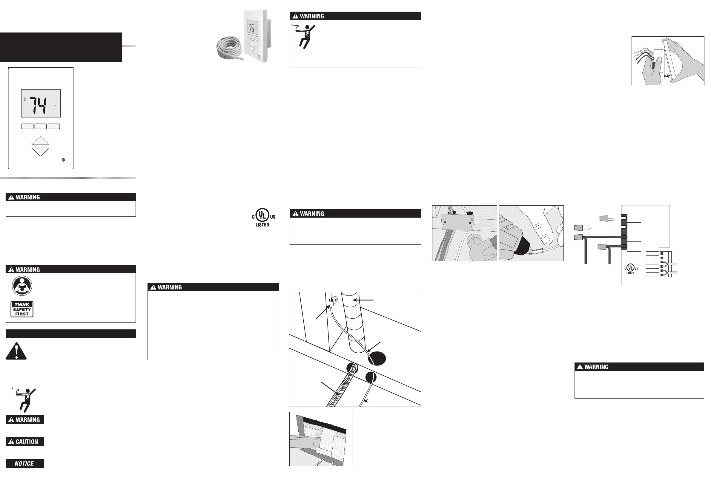
Before connecting the wires to the back of the thermostat,
detach the display front from the base.
Bottom Plate Work
• Drill or chisel holes at the bottom plate as indicated. One
hole is for routing the power lead conduit and the other is
for the thermostat sensor. These holes should be directly
below the electrical box(es).
Make sure 120 VAC is supplied to 120 VAC cables and 240
VAC is supplied to 240 VAC cables. Otherwise, dangerous
overheating and a fire hazard could result. Do not exceed
15-amps on this control.
SunStat Sensor Installation
•
The SunStat sensor can be installed with or without electrical
conduit depending on code requirements. Conduit is
recommended for added protection against nails and screws.
•
Do not place the sensor in the same conduit as the power
leads to avoid possible interference. Open a separate
knock-out in the bottom of the thermostat box. Feed the
sensor (and conduit, if used) through the knock-out, down
through the cut-out in the bottom plate, and out into the
floor where the heating cable will be installed.
•
If the sensor wire needs to be secured to the wall stud,
wait until after the wire or mat and sensor are completely
installed on the floor.
• At the sensor location, measure at least 1' into the heated
area. Mark the spot where the sensor will be attached to
the floor. Be sure to place the sensor exactly between two
of the heating wires. Ensure the sensor wire does not cross
over any heating wires.
• Do not locate the sensor outside the heating area or in a
gap between heating wires that is wider than the rest of the
floor. Do not locate the sensor where direct sun, hot-water
piping, heat duct, or lighting below will cause inaccurate
temperature reading. Do not locate the sensor where an
insulating item such as a rug is likely to be placed.
•
To make sure the sensor tip does not create a high spot
in the floor, it may be necessary to chisel a channel into
the floor and lay the sensor tip into the channel. Hot glue
the tip into place.
•
Do not cut the sensor wire or remove the black cable
protector. Strip the wire ends to 1/8" long.
Floor Heating Mat or Cable Power Lead Installation
• The shielded power lead can be installed with or without
electrical conduit (recommended for added protection
against nails or screws), depending on code requirements.
•
Remove one of the knock-outs in the electrical box to
route the power lead. If electrical conduit is not required by
code, install a wire collar to secure the power leads where
they enter the box. If conduit is required by code, install
1/2" (minimum) conduit from the bottom plate up to the
electrical box. For multiple power leads (multiple cables),
install 3/4" conduit.
•
Secure a steel nail plate over the cutout in the bottom plate
to protect the wires against baseboard nails later.
SunStat Relay Rough-in Wiring
A SunStat Relay C3 is used when more than 15 amps must
be controlled by one SunStat thermostat. The SunStat Core
is only compatible with the SunStat Relay C3. Do not use
other models.
• Pull 18 AWG to 24 AWG 2-conductor shielded wire from
the relay location to this control location. The wire may be
up to 100' (30 m) long.
• Strip the wire ends to 1/8" long.
Refer to the instructions provided with the SunStat Relay
C3 for additional details.
Power lead
conduit
Wire
clip
Power
lead
Sensor wire
Sensor wire
For retrofit installations,
cut out drywall and chisel
out the bottom plate to
route wires to control.
Sensor and relay connections are made to the terminal
block by inserting the wires into the square openings and
tightening the screws on the side.
•
Connect the sensor wires to the SENSOR terminals on the
thermostat. These connections are not polarity sensitive.
•
For a SunStat Relay C3, connect 2 wires from the relay to
the Com and Relay terminals on the thermostat. Ensure the
Com wire at the relay is the same conductor connected
to the Com terminal on the thermostat.
Designed and
assembled in Canada
E365015
Temp. Ind. &
Reg. Equip.
L1
L
LOAD 1
1
2
3
4
5
6
SENSOR
SENSOR
RELAY(B)
COM (A)
MAY 2015
1082-xx
GFCI CLASS A
L2
N
LOAD 2
Floor Heating
Floor Heating
Power:
120/240 ±10% V (ac)
60 Hz, 3 W
Load:
120/240 V (ac), 15 A
1800/3600 W
SunStat Core
(240 V)
(120 V)
(240 V)
(120 V)
Relay C3
Floor sensor
Mat or
Cable
power
lead
Power
supply
from
breaker
See over for operation details
Finish Thermostat Installation
• Ensure all connections are secure.
• Carefully press the wires back into the electrical box. Do
not use the control to push them.
•
Use the included screws to attach the thermostat base to
the electrical box. Do not overtighten.
• When re-attaching the display front, line up the top edge
with the base, then rotate the bottom towards the base.
Ensure the pins are not bent when connecting.
Make sure the wire connections are secure by gently tugging
on them. Otherwise, arcing could occur, causing dangerous
overheating and a possible fire hazard. For added security,
overwrap each wire nut connection with electrical tape.
While holding the base
section in one hand,
pull the lower half of the
display front towards
you to pivot it away from
the base.
Using the wire nuts included with the thermostat:
•
Connect the ground wire from the power supply to the
ground wire from the floor heating power lead. If the
electrical box is metal, use a short length of wire to connect
ground wires to the bonding screw.
•
Connect the white wire labeled LOAD 2 on the thermostat
to the white (or blue for 240 VAC) wire from the heating
mat or cable power lead.
•
Connect the black wire labeled LOAD 1 on the thermostat
to the black wire from the heating mat or cable power lead.
•
For 120 VAC connections, the L wire connects to the
black (L) hot conductor from the breaker panel. The N wire
connects to the white (N) neutral conductor.
•
For 240 VAC connections, the L1 connects to one side
of the 240 VAC supply from the breaker panel and the
L2 to the other.
Features:
• Floor temperature
control
• Thin profile
• Easy to use
• Three-Year warranty
SunStat
®
Core
Installation and
Operation Manual
Model# 108201, 108202, 108203