Page is loading ...

MOUNTING INSTRUCTIONS
Flexi Soft
FX3-EBX1 optimized motor
feedback splitter box
en
SICK AG • Industrial Safety Systems
Erwin-Sick-Straße 1
D-79183 Waldkirch • www.sick.com
8019030/13TK/2019-08-29 • TF_29
Printed in Germany (2019-08) • All rights
reserved • Subject to change without notice
1 About this document
These mounting instructions are original
mounting instructions.
1.1 Documentation for the Flexi
Soft system
These mounting instructions describe the
mounting of the following encoder connection
box for the FX3-MOCx Drive Monitor module of
a safety controller Flexi Soft:
FX3-EBX1 optimized motor feedback splitter
box
Facility for connecting two encoders with two
additional terminals per encoder for for-
warding signals
The installation, configuration and commis-
sioning of the Flexi Soft safety controller are
described in the following operating instruc-
tions.
Document Title Part no.
Operating
instructions
Flexi Soft
Hardware
8012999
Operating
instructions
Flexi Soft
Gateways
8012662
Operating
instructions
Flexi Soft
Designer
Software
8012998
Please refer also to the SICK homepage on the
Internet at www.sick.com. There you will find
the following files for download:
operating instructions
Flexi Soft Designer configuration software
EDS, GSD and GSDML files
1.2 Function of this document
These mounting instructions are designed to
address the technical personnel of the ma-
chine manufacturer or of the machine ope-
rator with regard to safe mounting of the
optimized motor feedback splitter box of the
Flexi Soft modular safety controller.
In addition mounting SICK protective devices
also requires specific technical skills which are
not detailed in this documentation.
These mounting instructions do not provide
instructions for operating machines on which
the Flexi Soft safety controller is, or will be,
integrated. Information on this is to be found
in the operating instructions of the machine.
2 On safety
This chapter deals with your own safety and the
safety of the equipment operators.
Please read this chapter carefully before
beginning with the installation work.
2.1 Qualified safety personnel
The Flexi Soft modular safety controller must only
be installed by qualified safety personnel. Qualified
safety personnel are defined as persons who …
have undergone the appropriate technical
training and
have been instructed by the responsible ma-
chine operator in the operation of the machine
and the current valid safety guidelines and
have access to the operating instructions for the
Flexi Soft safety controller and have read and
familiarized themselves with them and
have access to the operating instructions for the
protective devices connected to the safety con-
troller and have read and familiarized them-
selves with them.
2.2 Applications of the device
The Flexi Soft modular safety controller is a con-
figurable control system for safety applications. It
can be used
in accordance with IEC 61508 up to SIL3
in accordance with EN 62061 to SILCL3
in accordance with EN ISO 13849-1 up to cat. 4
and PL e
The degree of safety actually attained depends on
the external circuit, the design of the wiring, the
parameter configuration, the selection of the
safety sensors and their placement on the
machine.
Opto-electronic and tactile safety sensors (e.g.
light curtains, laser scanners, safety switches,
sensors, emergency stop pushbuttons) are con-
nected to the modular safety controller and are
linked logically. The corresponding actuators of the
machines or systems can be switched off safely
via the switching outputs of the safety controller.
2.3 Intended use
The Flexi Soft modular safety controller is only
allowed to be used within the specified operating
limits (voltage, temperature etc., see the technical
data and the section “Applications of the device”).
It must be used only by qualified personnel and
only on the machine where it has been installed
and initialized by qualified safety personnel in
accordance with the Flexi Soft operating instruc-
tions.
If the device is used for any other purposes or
modified in any way — also during mounting and
installation — any warranty claim against SICK AG
shall become void.
UL/CSA applications
Use 60 °C to 75 °C conductors.
To be used in a Pollution Degree 2 environment
only
Power must be supplied to the modules by
means of a power supply unit with safe isolation,
protected by a fuse as per UL248 with max.
100/V. Here V corresponds to the DC supply
voltage of maximum 42.4 V DC such that the
requirements of UL508 are met.
Note: The safety functions have not been tested by
the UL. Approval was provided as per UL508,
general use.
2.4 General safety notes and protective
measures
Observe the safety notes and protectiv
e
measures!
Please observe the following items in order
to ensure the intended use of the
Flexi Soft
modular safety controller.
During the mounting, installation and usage of
the Flexi Soft safety controller, observe the
standards and directives applicable in your
country.
The national/international rules and regulations
apply to the installation, commissioning, use and
periodic technical inspection of the Flexi Soft
system, in particular …
– Machinery Directive,
– Work Equipment Directive,
– the work safety regulations/safety rules.
Manufacturers and owners of the machine on
which a Flexi Soft safety controller is used are
responsible for obtaining and observing all
applicable safety regulations and rules.
It is imperative that the notices, in particular the
test notices of these mounting instructions be
observed.
The tests must be carried out by qualified safety
personnel or specially qualified and authorized
personnel and must be recorded and documen-
ted to ensure that the tests can be reproduced
and retraced at any time by third parties.
The Flexi Soft system complies, as per the
“
radiated emissions” generic standard,
with the requirements of class A (indus
-
trial applications)!
The F
lexi Soft system is therefore only suit-
able for use in an industrial environment
and not for private use.
2.5 Disposal
Unusable or irreparable devices should
always be disposed as per the applicable
national regulations on waste disposal (e.g.
European waste code 16 02 14).
3 Product description
This chapter provides information on the special
features and properties of the FX3-EBX1 optimized
motor feedback splitter box.
Please read this chapter before mounting,
installing and commissioning the device.
The connection box available as accessories eases
the connection of encoders to the encoder inter-
face on the FX3-MOCx modules, in particular for
encoders that are used for an FX3-MOCx as well as
for motor feedback in a drive system.
3.1 FX3-EBX1 optimized motor
feedback splitter box
The optimized motor feedback splitter box is
normally used together with a motor feedback
encoder.
Description
one 15-pin HD-D-Sub female connector with
M3 screws for the connection of the cable to the
FX3-MOCx
spring terminals for the connection of encoder
signals and two additional terminals per encoder
for forwarding signals
terminals for the shielding of both encoder
cables (from the encoder and to the motor
controller) for a low-impedance connection for
both cable shieldings
hardware ID in combination with the voltage
supply for sampling by the FX3-MOCx
mounting on DIN mounting rail
3.1.1 Encoder connections of the optimized
motor feedback splitter box
The optimized motor feedback splitter box has two
10-pin spring terminals (C1 and C2) for the con-
nection of two encoders.
Pin
Signal
Description
1
NC2
Not connected
1)
2
NC1
Not connected
1)
3
ENC1_24V
Encoder voltage supply
4
ENC1_0V
GND connection of the
encoder
5
ENC1_C–
Encoder 1, channel C,
negative signal
6
ENC1_C+
Encoder 1, channel C,
positive signal
7
ENC1_B–
Encoder 1, channel B,
negative signal
8
ENC1_B+
Encoder 1, channel B,
positive signal
9
ENC1_A–
Encoder 1, channel A,
negative signal
10
ENC1_A+
Encoder 1, channel A,
positive signal
Fig. 1: 10-pin spring terminal C1 on the optimized
motor feedback splitter box
Pin Signal Description
1
NC2
Not connected
1)
2
NC1
Not connected
1)
3
ENC2_24V
Encoder voltage supply
4
ENC2_0V
GND connection of the
encoder
5
ENC2_C–
Encoder 2, channel C,
negative signal
6
ENC2_C+
Encoder 2, channel C,
positive signal
7
ENC2_B–
Encoder 2, channel B,
negative signal
8
ENC2_B+
Encoder 2, channel B,
positive signal
9
ENC2_A–
Encoder 2, channel A,
negative signal
10
ENC2_A+
Encoder 2, channel A,
positive signal
Fig. 2: 10-pin spring terminal C2 on the optimized
motor feedback splitter box
Wire cross-section at C1 and C2
Single or fine stranded wire: 0.2 … 1.5 mm²
Fine stranded wire with ferrule: 0.25 … 1.5 mm²
AWG as per cULus: 24 … 16
1)
Not connected to the encoder connection box, is only used
for forwarding a signal.
3.1.2 Connection to the FX3-MOCx
The optimized motor feedback splitter box has
a 15-pin HD-D-Sub female connector C3 for
the connection to the FX3MOCx.
Fig. 3: 15-pin HD-D-Sub female connector C3
on the optimized motor feedback splitter box
Pin
Signal
Description
1
ENC1_A+
Encoder 1, signal pair A,
positive signal
2
ENC1_A–
Encoder 1, signal pair A,
negative signal
3
ENC1_24V
24 V voltage supply for
encoder 1
4
ENC2_A+
Encoder 2, signal pair A,
positive signal
5
ENC2_A–
Encoder 2, signal pair A,
negative signal
6
ENC1_B+
Encoder 1, signal pair B,
positive signal
7
ENC1_B–
Encoder 1, signal pair B,
negative signal
8
ENC_0V
GND connection for
encoder 1 and encoder 2
9
ENC2_B+
Encoder 2, signal pair B,
positive signal
10
ENC2_B–
Encoder 2, signal pair B,
negative signal
11
ENC1_C+
Encoder 1, signal pair C,
positive signal
12
ENC1_C–
Encoder 1, signal pair C,
negative signal
13
ENC2_24V
24 V voltage supply for
encoder 2
14
ENC2_C+
Encoder 2, signal pair C,
positive signal
15
ENC2_C–
Encoder 2, signal pair C,
negative signal

4 Mounting/dismantling
The encoder connection box must be
mounte
d in an environment that cor-
responds to enclosure rating
IP 54
(EN
60
529), e.g. in a control cabinet
with the enclosure rating
IP 54.
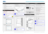
4.1 Mounting
Ensure that suitable ESD protective mea-
sures are taken during mounting. Otherwise
the device may be damaged.
Make sure that the supply voltage of the
Flexi Soft system is switched off.
Fig. 4: Mounting of the encoder connection
box
Hang the device onto the DIN mounting rail.
Ensure that the earthing spring contact is
positioned correctly. The earthing spring
contact on the device must contact the DIN
mounting rail securely and electrically
conductively.
Latch the device onto the DIN mounting rail
by pressing it lightly in the direction of the
arrow.
4.2 Dismantling
Remove the wiring.
Fig. 5: Dismantling the encoder connection
box
Insert two pointed objects (e.g. two screw-
drivers) in the opening for the two catch
springs and pull down the catch springs ().
Remove the module from the DIN mounting
rail in the direction of the arrow ().
5 Electrical installation
Switch off the entire machine or system!
The mac
hine/system could unintentionally
start up while you are connecting the
devices.
Please observe the appropriate safety
standards!
All safety
-
related parts of the system (wiring,
sensors and controls connected, configura
-
tion) must comply with the related s
afety
standards. This requirement can mean that
safety
-
related signals must be of redundant
design, or that single
-channel signal cables
must be laid with protection, or they must
be protected against short circuits by using
test outputs and/or regular fun
ction tests.
The Flexi Soft safety controller and the encoder
connection box fulfil the EMC requirements in
accordance with the basic specification
EN 61000-6-2 for industrial use.
To ensure full electromagnetic compatibility
(EMC), the DIN mounting rail must be connected
to FE.
The voltage supply as well as all signals connec-
ted have to fulfil the regulations for extra-low
voltages with safe separation (SELV/PELV).
All safety sensors and actuators connected as
well as wiring and installation have to fulfil the
required safety characteristics.
On the replacement of the module or encoder
connection box, it must be ensured the pin
assignment is made correctly, e.g. by marking or
laying in a suitable manner.
For additional information that is to be taken
into consideration when the Flexi Soft safety
controller is used refer to the “Flexi Soft Hard-
ware” and “Flexi Soft Designer Software”
operating instructions.
6 Configuration and
commissioning
Commissioning requires a thorough check
by qualified safety per
sonnel!
Before the initial commissioning of the
system in which you are using a Flexi Soft
system, it must be checked and released
documented by qualified safety personnel.
7 Technical data
See the “Flexi Soft Hardware” operating
instructions.
8 Ordering information
Device
type
Part
Part no.
FX3-EBX1
Optimized motor
feedback splitter
box for FX3-MOCx
2079867
For suitable connection cables please refer to the
“Flexi Soft Hardware” operating instructions.
/