Page is loading ...

122
Soundweb
TM
SoundwebSoundweb
SoundwebSoundweb
Soundweb
TMTM
TMTM
TM
9014 9014
9014 9014
9014
Installation Guide

123
Soundweb
TM
Regulatory Information
An example of this equipment has been tested and found to comply with the following European
and international Standards for Electromagnetic Compatibility (only when used with a metal
wallbox).
Radiated Emissions (EU): EN55022 (1995) Associated Equip.
Immunity (EU): EN50082/1 (1997) RF Immunity, Fast Transients ESD
Radiated Emissions (USA): FCC part 15 Class A
v1.0 MR/JMK 8th September 1999
Important safety information - read and follow
It should not be necessary to remove any protective earth or signal cable shield
connections to prevent ground loops. Any such disconnections are outside the
recommended practice of BSS Audio, and will render the EMC certificate void.
We have written this guide with the aim of helping installers and sound engineers alike to
get the most out of the 9014. We recommend that you read this manual, particularly the
section on mechanical installation, before attempting to operate the unit.
We welcome any comments or questions regarding the 9014 or other BSS products, and
you may contact us at the address or World Wide Web site given below.
BSS Audio:
Cranbourne House,
Cranbourne Industrial Estate,
Potters Bar,
Hertfordshire,
EN6 3JN.
www.bss.co.uk
Tel: +44 (0)1707 660667 Fax: +44 (0)1707 660755
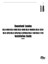
Mechanical Installation
Dimensions of the unit are shown below.
Three 9014 devices can be mounted side-by-side with a 1U panel, available from BSS
Audio as part number Z-999-FPNL.
BSS Audio also offer a universal AC input +24V DC power supply, available as part
number Z-999-PSU.
The panel can be used to rack mount one or two 9014 devices if required, and can be
fitted with the Z-999-PSU power supply, with the use of a PSU tray; part number Z-999-
TRAY.

124
Soundweb
TM
Use
The 9014 requires 12-24v DC to be supplied externally. There are two ways of getting
power into the unit:
• Connect a 24v 1A DC power supply to the 2.4mm barrel connector. Up to nine more
9014s may be powered from the paralleled combicon connector.
• Connect a 12-24v DC power supply to the combicon connector.
A pair of 9014 Fibre Interface units are used to replace a standard category 5 Soundweb
network cable. Each fibre cable will transfer 8 channels of digital audio plus control data.
To utilise the fibre system, each end of the fibre link requires one 9014 device. Each
device is equipped with an RJ-45 Soundweb network cable jack into which the network
cable is connected, and two snap-in SC type fibre connectors.
Two fibre cables are then required to connect between 9014 devices - this is to enable the
bi-directional data transfer.
Network socket
This connects to either the Network Out socket or the Network In socket on another unit.
The connecting cable is CAT. 5 network cable, terminated with RJ45 connectors, with all
8 cores wired straight through.
Note that the twisted pairs in any CAT.5 network cable must be wired to the following pin
pairs at each terminal:
1 (White-Orange) with 2 (Orange); 3 (White-Green) with 6 (Green);
4 (Blue) with 5 (White-Blue); 7 (White-Brown) with 8 (Brown)
Note:
Ensure that all Out sockets are connected to their correct In sockets at each end of every
cable. Connecting In - In (or Out - Out) will result in improper operation of the network.

125
Soundweb
TM
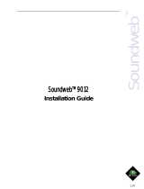
Rear panel connections
The unit has the following connections on the rear face:
Power
Phoenix socket: Power supply to or from a 9011 power interface.
Barrel socket: Power supply from a Z-999-PSU power supply.
Network
Signal at the network socket is in electrical form.
The network socket is bi-directional, so information can pass in and out of the 9014 unit
through this connection simultaneously. It is also auto-sensing, meaning that it can be
connected to either an OUT or an IN socket on one of the other Soundweb series units.
Fibre-in/out
Signal at the fibre in/out sockets has been converted to an optical format.
Information arriving from a Soundweb unit at the network socket is passed through the
9014 for conversion, and out of the fibre out socket.
Information arriving at the fibre in socket is passed through the 9014 for conversion and
out of the network socket.
Front panel LED functions
The unit has three LED indicators showing:
Power
Steady - This indicates the power supply is functioning.
Fibre-in
Steady – Data is arriving on the fibre input.
Intermittent – You have exceeded the optical power budget by either exceeding the
maximum fibre length or by having too much attenuation in fibre splices. See the
specification section.
Cable-in
Steady – Data is arriving on the cable.

126
Soundweb
TM
Technical specifications
PowerPower
PowerPower
Power
DC Supply 12-24V DC, <5VA
Connector Phoenix screw terminal or 2.4mm inline barrel
connector
NetworkNetwork
NetworkNetwork
Network
Single RJ-45 Auto-sensed input node or output node - no setup required.
Max cable length 20m
Fibre ConnectionFibre Connection
Fibre ConnectionFibre Connection
Fibre Connection
Snap-in SC fibre input
Snap-in SC fibre output
Fibre cableFibre cable
Fibre cableFibre cable
Fibre cable
Multimode 62.5/125um or Multimode 50/125um
Optical Power BudgetOptical Power Budget
Optical Power BudgetOptical Power Budget
Optical Power Budget
10dB
Max fibre length 2000 metres/6550 feet/1.2 miles
N.B this distance is based on the optical power budget and maximum allowable network
delay of one sample in any one ring.
Dimensions 5.3" x 5.5" x 1.4"
135 x 139 x 36mm
/