Page is loading ...

ROCKSLIDEENGINEERING.COM - NEED ASSISTANCE? 435.752.4580 - PAGE 1 REVISED 5/23/2023
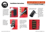
To watch an install overview of our step
slider, scan the QR code with your
smart phone camera.
Please note that this manual will have
the latest changes to the install process.
https://youtu.be/DSh8yatg4p8
Newest features:
• 40% stronger with High Strength Low Alloy Steel (HSLA).
• All new Smart Motor for improved, consistent motion. Intelligent acceleration and
deceleration provides quiet, smooth operation.
• Updated harness for simplified, quicker installation.
• Improved mechanical components increase reliability and reduce maintenance (warranty).
INSTALLATION MANUAL
Made in the USA
BD-SS-300-JL4
BD-SS-300-JL2
GEN 3 JL STEP SLIDER
2017 - PRESENT

ROCKSLIDEENGINEERING.COM - NEED ASSISTANCE? 435.752.4580 - PAGE 2 REVISED 5/23/2023
Description Quantity
Electric Step Slider (Pair) 2
Bump stop plate with VHB backing 2
Wiring harness 1
Double sided adhesive strips 4
Door sensor 4
Magnets 4
Alcohol wipes 4
Rocker cutoff switch 1
1/4” push in plug 10
M10 flange bolt 1
Cable clip 1
Floor Plug Grommet 2
5/16” - 18 nylock nut (pinch seam) 8
5/16” grade 8 washer (pinch seam) 8
1/4” - 20 nylock nut (pinch seam) 4
1/4” - 20 grade 8 washer (pinch seam) 4
5/16” - 18 X 5/8” grade 8 hex head bolt 24
5/16” SAE yellow zinc washer 24
Front bracket (drop style) 2
Middle bracket (short style) 2
Rear brackets (long style) 2
Rocker cutoff switch bracket 1
Zip Tie 10
Tools Required
10 mm socket 7/16” socket
18 mm socket 1/2” socket
8 mm socket Wrench with 3-4”extension
Breaker bar 1/2” Box end ratcheting wrench
7/16” Box end ratcheting wrench
**Optional for quicker install
Impact Gun with
adapters
Heavy Duty Impact Gun with 1/2”
driver
Front Bracket
Middle Bracket
Rear Bracket
4 in.
Drop Style
5 3/16 in.
Long Style
6 in.
Long Style

ROCKSLIDEENGINEERING.COM - NEED ASSISTANCE? 435.752.4580 - PAGE 3 REVISED 5/23/2023
Harness Diagram - 1
A. CIRCUIT BOARD CONNECTOR
B. MOTOR CONNECTOR
C. LIGHT CONNECTOR
D. REAR DOOR SENSOR CONNECTOR
E. FRONT DOOR SENSOR CONNECTOR
F. ROCKER SWTICH CONNECTORS
G. ROCKER SWITCH
H. BATTERY TERMINALS
I. FUSE HOLDER
B
G
A
C D: Green
E: Blue F
H
I

ROCKSLIDEENGINEERING.COM - NEED ASSISTANCE? 435.752.4580 - PAGE 4 REVISED 5/23/2023
Harness Diagram - 2
Baery
Harness Route: Located outside of
the Jeep aached to the top of
the frame rail.
Harness Route: Located inside of the
underneath the rocker panels.
G
H
Harness Route: Passenger Side
Harness Route: Driver Side
Harness on 2 Door Models: You will have
excess harness length with a two door.
Secure extra length with zip es and follow
front door sensor and magnet instrucons.

ROCKSLIDEENGINEERING.COM - NEED ASSISTANCE? 435.752.4580 - PAGE 5 REVISED 5/23/2023
Harness Diagram - 3
Harness Route: Located underneath
Jeep aached to the crossmember.
A A
B
B
C
D
C
D
E
E
F
H
I
Harness Route: Located
inside of the Jeep under-
neath the rocker panels.
Harness Route: Located
outside of the Jeep
aached to the top of
the frame rail.
IMPORTANT
You must connect ground wire to
an exisng body bolt. If you try to
aach both wires to baery
terminals, you will lose 6 in. of
harness length. (see step 2)

ROCKSLIDEENGINEERING.COM - NEED ASSISTANCE? 435.752.4580 - PAGE 6 REVISED 5/23/2023
Step 1
REMOVE THE FUSE FROM THE
HARNESS
INSTALLING THE PASSENGER SIDE
OF THE HARNESS
Once the fuse is removed: trace the
passenger side of the harness with the fuse
case, red wire (+) and black wire (-) from
the rear passenger door along the frame rail
making sure to run the harness behind the
body bolts.
Underneath the passenger side front door,
there is a factory hole where you can se-
cure your wiring harness. Use this cable
clip and M10 flange bolt. Do not tighten
completely until full harness is in place.
Fasten the first junction of wires to the
existing factory harness with a zip tie be-
hind the body bolts. Do not pull the zip
ties tight yet. Leave the remainder of the
harness at the passenger door free.
I
Passenger Side Harness Zip Tie & Cable Clip Anchor Points
2: Zip Tie 1: Zip Tie 3: Cable Clip
Factory Harness RSE Harness
Remove any factory sliders or steps from the vehicle and set aside. You will not need any of the hardware from the factory parts
removed. We provide all new hardware for our installation.

ROCKSLIDEENGINEERING.COM - NEED ASSISTANCE? 435.752.4580 - PAGE 7 REVISED 5/23/2023
Step 2
CONNECTING TO THE BATTERY
TERMINAL
ENSURE THE FUSE IS PULLED FROM
THE WIRING HARNESS
Run the red wire (+) and black wire (-)
with the fuse case along the frame rail, up
the fire wall.
Attach the red wire (+) to the positive
terminal. The black wire (-) will attach to
an existing body bolt on the Jeep. Ensure it
has good metal to metal contact to keep
paint from interfering with the connection.
IMPORTANT
You must attach the ground wire to the
body bolt. If you don’t, you will lose 6
inches of harness length on JL models.
Step 3
SECURE HARNESS
With the wires attached to the battery, pull
excess wire harness down from battery to
frame rail and secure this section of the
harness by tightening the M10 flange bolt
and cable clip. Tighten up the zip ties
along the frame rail to the first junction of
wires on the harness at the rear passenger
door.
Inner fender lining has been removed to have easier access running harness up rewall.

ROCKSLIDEENGINEERING.COM - NEED ASSISTANCE? 435.752.4580 - PAGE 8 REVISED 5/23/2023
Step 4
REMOVE ROCKER PANELS
Pop the rocker panels on the rear of the
passenger side to allow access to the rear
floor plug.
Peel up the carpet and look for this hard
plastic plug sealed to the floor.
Remove the plug by using a screwdriver
and hammer to hit it up and out from
underneath the Jeep.
Replace with black rubber grommet
provided.
Step 4 Note - 4xe Owners
ADDITIONAL PANEL REMOVAL
In order to pop the rear rocker panels on
both sides, you will need to remove the
side panels that cover the ends of the
battery compartment found under the rear
seat.
Remove the two bolts on the end and pop
the panel off and set aside.
You can now pop the rear rocker panels
and peel up the carpet to allow access to
the floor plug.

ROCKSLIDEENGINEERING.COM - NEED ASSISTANCE? 435.752.4580 - PAGE 9 REVISED 5/23/2023
Step 6
INSTALLING THE DRIVER SIDE OF
THE HARNESS
Pop the front and rear panels on the driver side
and peel back the carpet to expose the rear floor
plug. Remove the plastic plug and replace with
the provided grommet. Thread the green door
sensor (D), blue door sensor (E) and rocker
switch (F) connectors through the floor plug
and into the cab.
Leave the rear green door sensor (D) in the
back. Run the front blue door sensor (E) and the
Rocker Switch (F) along the existing harness
towards the front of the Jeep.
The drivers side circuit board (A) and motor (B)
connectors remain outside underneath the jeep.
Step 5
INSTALLING THE PASSENGER SIDE OF THE HARNESS
Thread the green door sensor (D) and blue door sensor (E) connectors up
through the rear floor plug on the passenger side. The circuit board (A), Motor
(B) and light (C) connectors will remain visible on the passenger side under
the vehicle.
Pull the remainder of the harness from the passenger side to the driver side
over the frame rail. Run it along the rear cross member in line with the rear
wheels and secure the harness with zip ties to the cross member.
D E
E
D
F
Optional
If desired, apply a small amount of silicon into
the passenger side grommet where the sensor
wires come thru to fill any gaps.
Optional
If desired, apply a small amount of silicon into
the driver side grommet where the sensor and
switch wires come thru to fill any gaps.

ROCKSLIDEENGINEERING.COM - NEED ASSISTANCE? 435.752.4580 - PAGE 10 REVISED 5/23/2023
Step 7
ROCKER SWITCH
INSTALLATION
Install master switch cutoff bracket
onto the JL OBD2 port bracket.
Remove the OBD2 port screw using
an 8mm socket.
Insert screw through large hole on
the master switch bracket, and then
back through the OBD2 port
bracket, and install back into place
to hand tight.
Pull the wires through the bracket.
Plug red and black wires into place.
The wires can be plugged in on
either side. Push the button back into
the bracket until it snaps into place.
Turn switch to off position marketed
with “OFF” or “O”.
Step 8
BODY BOLTS
Locate the three body bolts on the
underside of the vehicle on each side.
Loosen the three body bolts about 1/4”
to allow free movement of the washer
up and down.
Breaker bar may be required to loosen
the body bolts.
TIP FROM A MECHANIC
As you start loosening, as soon as you
hear the bolt pop or feel it bind, reverse
direction 1/8 to 1/4 turn to clear the
threads. This will make it easier as you
progress. Even if you do not hear it pop
do the reverse direction early on to
prevent body bolt damage.
IMPORTANT
RSE is not responsible for any body bolt
damage. Please visit your Jeep dealership
or regular mechanic for assistance.

ROCKSLIDEENGINEERING.COM - NEED ASSISTANCE? 435.752.4580 - PAGE 11 REVISED 5/23/2023
Step 9
BRACKET INSTALLATION
Install each bracket between the bolt head
and the washer. Leaving them loose for now.
3. Front Bracket 2. Middle Bracket 1. Rear Bracket
4 in.
Drop style
5 3/16 in.
Long Style
6 in.
Long Style
2 1 3
IMPORTANT
In some cases the washer doesn’t
allow enough gap you will have to
use a small file to remove the two
threads closest to the back side of
the washer.
You can also try knocking the
brackets into place between the
bolt head and washer with a
rubber mallet.

ROCKSLIDEENGINEERING.COM - NEED ASSISTANCE? 435.752.4580 - PAGE 12 REVISED 5/23/2023
Step 10
BUMP STRAP INSTALLATION
In preparation for the bump straps, make sure
the angled section of the Jeeps body near the
pinch seam is thoroughly cleaned and wipe
it down with an alcohol pad to prep the
area. This will ensure good contact of the
bump strap adhesive with the painted
surface.
IMPORTANT
Before placing the bump strap to the
Jeep, do an alignment check. 1 3/4 in.
from the bottom of the door seal to the
top of the bump strap is a good location.
Starting at the rear fender and working
toward the front fender, take your time with
the actual installation.
Make sure the notch in the bump strap lines
up with the rear body seam.
Slowly removing the adhesive as you move
along the body of the Jeep, holding the bump
strap in place. Press firmly where the red tape
backing is removed.
IMPORTANT
Once that tape adheres to the Jeep, it is
designed not to come off. The bump strap
protects the Jeep’s paint and fills the gap
between the Jeep and Step Slider.

ROCKSLIDEENGINEERING.COM - NEED ASSISTANCE? 435.752.4580 - PAGE 13 REVISED 5/23/2023
Step 11
STEP SLIDER INSTALLATION
Before placing the Step Slider on the Jeep,
pull the motor connector through the last
cutout located next to the circuit board so it
hangs out of the way.
Tighten the body bolts on each side of the
vehicle with the brackets in place so they are
snug but still have a small amount of swivel.
Lift the Step Slider onto the Jeep lining up the
bolts of the step body with the pinch seam
holes of the Jeep.
As you slide the bolts into the holes, make
sure the brackets are above the step body.
When you have the bolts of the step slider
inserted into the pinch seam holes, the Step
Slider will hang and stay on the Jeep allowing
you to secure with nyloc nuts.
Secure the Step Slider to the pinch seam by
using two 1/4” nyloc nuts and four 5/16”
nyloc nuts with washers.
Since the six bolts come in two sizes, work
from the front of vehicle toward the back. In
this order the nyloc nuts sizes will be 1/4,
5/16, 5/16, 5/16, 1/4, 5/16.
Tighten the pinch seam nuts. 1/4” nuts torque
to 8 ft. lbs. and the 5/16” nuts torque to 18 ft.
lbs.
Repeat steps for other side.
IMPORTANT
Make sure your wires are not
being pinched between the
brackets, Step Slider or body
of the Jeep.

ROCKSLIDEENGINEERING.COM - NEED ASSISTANCE? 435.752.4580 - PAGE 14 REVISED 5/23/2023
Step 14
PLUGGING IN THE HARNESS
Pull the circuit board (A) connector through
cutouts on the back of the step slider bringing
wire out toward the bottom cutout hole by the
circuit board.
Plug the circuit board (A) connector from
harness into the circuit board. Push firmly till
you hear a click.
Route the long connector wire from the motor
through the back of step slider and plug the
motor connector (B) from harness into the
wire from the motor. Secure all wires with
zip tie so they don’t hang down.
NOTE
The wires for the motor connector (B) will be
crossed over red to yellow and yellow to red.
This is the way.
NOTE
The additional wire on the harness is for the
optional light kit connector (C). Tuck away
inside of the step slider for later installation.
A
B
C A
B
TIGHTEN BODY BOLTS
Tighten the six body bolts by torquing these
to 80 ft. lbs.
STEP SLIDER INSTALLATION
Bolt the Step Sliders to the body bolt brackets
using four 5/16” -18x5/8” hex head bolts and
washers on each bracket. You can use a hole
punch or screw driver to help line up the
holes of the brackets with the step. Do not
tighten hex bolts until you have four bolts in
each bracket. Then tighten and torque the hex
head bolts to 20 ft. lbs. Repeat for other side.
NOTE - Skid Plate Install
If you will be installing our skid plates leave
the 2 rear bolts of the front brackets out until
the skid plate is installed. The skid plate will
come with 4 longer bolts (2 each side) to
replace these on either side. Make sure you
leave these bolts out before installing the skid
plate rivets.
Step 13
Step 14

ROCKSLIDEENGINEERING.COM - NEED ASSISTANCE? 435.752.4580 - PAGE 15 REVISED 5/23/2023
I
Step 15
CALIBRATION CYCLE
With both of your step sliders installed, it is time to
calibrate the circuit board.
Install the fuse into fuse holder (I) of our wire harness
located at the battery.
Turn ON the switch you installed under the dash.
E
D
Step 16
Start the calibration with the Driver’s Door.
Locate the blue sensor wire (E) and grab a sensor wire
setup.
Step 17
Make sure the step is clear of all obstructions
prior to calibration.
Plug the door sensor into the blue sensor wire (B) of the wire harness. The
step will fully deploy.
Unplug the sensor from the wire harness and the step will fully retract after
approximately a three second delay.
The calibration is complete on the driver’s side step.
Repeat this process on the passenger side step to calibrate it.
E

ROCKSLIDEENGINEERING.COM - NEED ASSISTANCE? 435.752.4580 - PAGE 16 REVISED 5/23/2023
Step 18
INSTALLING DRIVER DOOR SENSOR
Run the front door sensor (E) along the existing
factory harness. Use the alcohol wipes to clean
directly below the door latch Striker. Make sure
the surface area is clean and ready for the door
sensor adhesives.
With the door sensor in hand, use the double sid-
ed adhesive and attach it to the back of the sensor.
Press the sensor firmly below the door striker.
Expose the adhesive on the foam wire protector
next to the sensor and wrap the foam around the
frame metal. Connect the door sensor to the blue
wire (E) connector and the step will deploy.
When you are finished, you can tuck all of the
carpeting back in and reinstall the plastic rocker
trim. Snapping right into place.
Step 19
1 Magnet
DRIVER DOOR MAGNET INSTALLATION
IMPORTANT Do a test fit to make sure the
magnet is properly aligned with the door sensor by
placing a magnet on the door but not using the
adhesive backing yet.
Magnet location is on the outer part of the door.
Opposite where the sensor was placed below the
door striker. Roughly 1/4 in. down from the bot-
tom screw below the door latch.
Close the driver’s door. If the sensor and magnet
are lined up, the step will retract.
Once you have confirmed magnet location in door,
use the alcohol pad to clean the inside of the door.
Peel off the backing and firmly press the magnet
into place.
Now close the driver’s door again. If the sensor
and magnet are lined up, the step will retract. If it
does not retract, check alignment of magnet to
sensor.

ROCKSLIDEENGINEERING.COM - NEED ASSISTANCE? 435.752.4580 - PAGE 17 REVISED 5/23/2023
Step 20
INSTALLING REAR DRIVER DOOR
SENSOR (4DR)
Remove the trim panel. Run the rear door sen-
sor (D) along the existing factory harness and
up the inner portion on the B Pillar.
Using the alcohol wipes, clean this area above
the rear door hinge. Make sure the surface area
is clean and ready for the door sensor adhesives.
With the door sensor in hand, use the double
sided adhesive and attach it to the back of the
sensor.
Place the sensor 1/4” above the hinge bracket.
Press the sensor firmly. Expose the adhesive on
the foam wire protector next to the sensor and
wrap the foam around the frame metal. Connect
the door sensor to the green wire (D) connector
and the step will deploy.
Step 21
IMPORTANT
Rear door sensors are located on the INNER portion of the door on the B Pillar.
REAR DRIVER DOOR MAGNET
INSTALLATION (4DR)
IMPORTANT Do a test fit to make sure the magnet
is properly aligned with the door sensors.
Using the alcohol pad, clean the foam on the inside of
the door. Peel off the backing and firmly press the
magnet into place.
Magnet location is on the inner side of the door.
Opposite where the sensor was placed on the B Pillar.
Close your rear door after placing the sensor. Opposite
the sensor, on the inner part of your door, a foam piece
will indent slightly. Place your magnet in the center of
the indented foam.
Now close the rear driver door. If the sensor and
magnet are lined up, the step will retract. If it does not
retract, check alignment of magnet to sensor.
1 Magnet

ROCKSLIDEENGINEERING.COM - NEED ASSISTANCE? 435.752.4580 - PAGE 18 REVISED 5/23/2023
Step 23
Use these plugs to cover the holes in the Step
Slider.
You are done!
Scan this code to leave us a review!
Step 22
PASSENGER SIDE SENSORS AND MAGNETS
Repeat Steps 18-21 to install door sensors and magnets
on the passenger side of your vehicle.
NOTE
On the rear door place the sensor at the hinge bracket.
This is different than driver’s side to ensure proper
alignment of sensor to magnet.

ROCKSLIDEENGINEERING.COM - NEED ASSISTANCE? 435.752.4580 - PAGE 19 REVISED 5/23/2023
FREQUENTLY ASKED QUESTIONS:
I just installed my steps and they are
not coming down when I open the door.
Double check the connections. Check the fuse to make sure it is plugged in. Is the on / off
switch getting power? Is the circuit board plugged in? Are the door sensors plugged in?
I opened my door a bunch of times and
the system just shut off. What happened?
Our systems have built-in protection against quick cycling like this to prevent damage.
Simply remove your 20 amp fuse and re-install.
This will reset the system and allow it to work normally again.
Everything is plugged in and the switch is
turning on and off, but the steps still
won't deploy.
Check the motor first. Simply unplug it from the wiring harness and apply external 12V power
to the leads. One position will make them deploy. Switch the leads again to make them retract.
If this works, plug the motor back into the harness. We test each and every motor that leaves
our factory by hand along with assembling your step slider by hand. These may fail, but it is
extremely rare after we send them after having tested them. If you test the motor and all you
hear is a clicking sound but nothing happens, there is likely internal damage.
I tested the motor, and it works. I checked
the sensors individually, and the system
still won't work. The steps don't deploy
unless I do it manually with 12V power.
In rare circumstances, the circuit board that runs the system may be faulty.
Send us an email at Warranty@rockslideengineering.com to request a new circuit board.
I was off-roading, left my system on,
someone left the door ajar and I ripped
my step off on a rock. What now?
We can replace these parts for you at cost. You will have to remove the step off your vehicle to
replace the innards. Call us and we’ll figure out what you need exactly! If you prefer us to do
the repair we will do that for you! You will have to cover shipping to us and the cost of the
parts, but we will ship it back to you (from our warehouse to your house) on our account.
Everything is working now. But I want to
take my doors off and have the steps still
work.
We sell a door delete kit you can bypass the door sensors with. Part# SL-DD-100
comes with everything you need allowing to remove your doors and manually deploy and
retract the steps with the push of a button.
The steps deployed and won’t retract.
What is going on?
Chances are your magnets are misaligned. To diagnose which door needs to be adjusted, un-
plug the rear sensors with the front doors closed. If your steps come up, then it was the rear
doors that need to be aligned with your magnet. If the step stays down, the front door needs to
be aligned. Open your door, shift the magnet in a direction, and shut it again. Repeat until the
step comes up when the door is shut. Mark the magnet placement on the front door. Plug the
rear door sensor in, shut the rear door and front door, and see if it comes up. If not, the rear
door is misaligned (Since we just aligned the front door we know it’s the rear door now). Re-
peat the previous process of opening your door, shifting your magnet, and shutting your door
until the step comes up. It may take a few tries.
OPTION 2
Check the sensors. Unplug both of them from the wiring harness on the side that is not work-
ing, and plug one back in. Manually test your sensors by putting a magnet really close (but not
touching) to the sensor. Does it make the step retract? When the magnet is away, the step
should deploy. If the steps deploy right after installation, more than likely your magnets just
need to be aligned. Do this one by one with each sensor by the method above. Install one sen-
sor, test, align the magnet on the door, test, and then mark the position of the magnet so if for
some reason they do move out of place you can easily realign them.

ROCKSLIDEENGINEERING.COM - NEED ASSISTANCE? 435.752.4580 - PAGE 20 REVISED 5/23/2023
WARRANTY POLICY
LIMITED TWELVE (12) MONTH WARRANTY FOR FINISH AND ELECTRICAL COMPONENTS
Rock-Slide Engineering, LLC (“RSE”) warrants to the original purchaser that (a) the structural and mechanical com-
ponents of the Step Sliders will be free of defects in material and workmanship for the lifetime of the Step Sliders (the
“product”), and (b) the finish (powder
coat) and the electrical components (including the motor) will be free of defects in material and workmanship for a
period of twelve (12) months from the original date of purchase. This warranty applies only to the original retail pur-
chaser. Warranty is void if product was not
purchased directly from R- SE or from an authorized RSE retailer or reseller. This warranty applies only with regard
to the product as originally installed to the original vehicle. This warranty does not cover removal or reinstallation of
the product.
To exercise this warranty and receive any warranty service, the original purchaser must provide RSE with proof of
purchase and date of purchase that is acceptable to RSE, such as a copy of the original purchaser’s purchase receipt.
The original purchaser must return the
defective product to RSE along with a description of the problem, a copy of the original purchase receipt, the original
bill of sale and all contact information (name, address, telephone number and email address). To begin the warranty
process, the original purchaser must
email RSE’s warranty department. During this warranty term, and upon the original purchaser’s valid exercise of this
warranty, RSE shall, at its option, repair or furnish the replacement product in the event the original product is deemed
by RSE to be defective. RSE’s sole liability shall be for repairing or
replacing the product, but RSE may refund the purchase price at its sole discretion and option. The original purchaser
is responsible for prepayment of all shipping and/or transportation charges with respect to the exercise of this warran-
ty. The product may change without
notice. In the event of a product change, RSE has no obligation to upgrade or modify any older generation product.
THE WARRANTY SET FORTH HEREIN IS THE ONLY WARRANTY COVERING THE PRODUCT. NO OTH-
ER WARRANTY EXISTS, EXPRESS OR IMPLIED, INCLUDING, WITHOUT LIMITATION, IMPLIED WAR-
RANTIES OF MERCHANTABILITY AND/OR FITNESS FOR A PARTICULAR PURPOSE. No retailer, reseller,
dealer, agent, or employee is authorized to make any modifications, extensions, amendments, or additions to this war-
ranty.
This warranty shall be void in its entirety if RSE determines that the product installation was modified, changed, al-
tered, customized or in any way used other than as instructed. Installation of the product without strictly adhering to
the installation instructions shall void this warranty. Installation must be on the proper vehicle or warranty is void.
RSE SHALL NOT BE LIABLE FOR SPECIAL, INDIRECT, INCIDENTAL OR CONSEQUENTIAL DAMAGES,
UNDER ANY LEGAL THEORY AND/OR UNDER ANY CIRCUMSTANCE WHATSOEVER. IN ANY EVENT,
ANY DAMAGES IN ANY SITUATION SHALL BE LIQUIDATED DAMAGES AND MAY NOT EXCEED THE
RETAIL PRICE OF THE PRODUCT. RSE SHALL NOT BE LIABLE FOR ANY LOSS, DAMAGE OR INJURY
DIRECTLY OR INDIRECTLY ARISING FROM THE USE OF OR INABILITY TO DETERMINE THE USE OF
THE PRODUCT. THE ORIGINAL PURCHASER IS RESPONSIBLE TO DETERMINE THE SUITABILITY OF
THE PRODUCT FOR ITS INTENDED USE, PRIOR TO USING THE PRODUCT, AND THE ORIGINAL PUR-
CHASER ASSUMES ALL RESPONSIBILITY AND RISK IN CONNECTION THEREWITH.
For questions or concerns: please contact our office at 435-752-4580 and ask for the warranty department or email us
/