Page is loading ...

Crestron PAC2
®
Professional Automation Control System
Operations Guide

The specific patents that cover Crestron products are listed at patents.crestron.com.
Crestron, the Crestron logo, Cresnet, Crestron Green Light, Crestron Studio, Crestron Toolbox, D3 Pro, e-Control, PAC2, RoomView and SIMPL+ are
either trademarks or registered trademarks of Crestron Electronics, Inc. in the United States and/or other countries. ColdFire is either a trademark or
registered trademark of Motorola, Inc. in the United States and/or other countries. Other trademarks, registered trademarks and trade names may be
used in this document to refer to either the entities claiming the marks and names or their products. Crestron disclaims any proprietary interest in the
marks and names of others. Crestron is not responsible for errors in typography or photography.
This document was written by the Technical Publications department at Crestron.
©2013 Crestron Electronics, Inc.
Regulatory Compliance
As of the date of manufacture, the PAC2 has been tested and found to comply with specifications for CE
marking and standards per EMC and Radiocommunications Compliance Labelling.
Federal Communications Commission (FCC) Compliance Statement
CAUTION: Changes or modifications not expressly approved by the manufacturer responsible for
compliance could void the user’s authority to operate the equipment.
NOTE: This equipment has been tested and found to comply with the limits for a Class B digital device,
pursuant to part 15 of the FCC Rules. These limits are designed to provide reasonable protection against
harmful interference in a residential installation. This equipment generates, uses and can radiate radio
frequency energy and, if not installed and used in accordance with the instructions, may cause harmful
interference to radio communications. However, there is no guarantee that interference will not occur in a
particular installation. If this equipment does cause harmful interference to radio or television reception,
which can be determined by turning the equipment off and on, the user is encouraged to try to correct the
interference by one or more of the following measures:
• Reorient or relocate the receiving antenna
• Increase the separation between the equipment and receiver
• Connect the equipment into an outlet on a circuit different from that to which the receiver is connected
• Consult the dealer or an experienced radio/TV technician for help
Industry Canada (IC) Compliance Statement
CAN ICES-3(B)/NMB-3(B)

Crestron PAC2 Professional Automation Control System
Operations Guide – Doc. 5941A Contents • i
Contents
Professional Automation Control System: PAC2 1
Introduction ............................................................................................................................... 1
Features and Functions ................................................................................................ 1
Specifications .............................................................................................................. 4
Physical Description .................................................................................................... 5
Built-In Cresnet Hub/Repeater .................................................................................. 10
Setup ........................................................................................................................................ 12
Network Wiring ......................................................................................................... 12
Installation ................................................................................................................. 12
Hardware Hookup ..................................................................................................... 14
AC Power Connection ............................................................................................... 16
Uploading and Upgrading ........................................................................................................ 18
Establishing Communication ..................................................................................... 18
Programs and Firmware ............................................................................................ 19
Program Checks ........................................................................................................ 19
Problem Solving ...................................................................................................................... 20
Troubleshooting ......................................................................................................... 20
Troubleshooting Communications ............................................................................ 20
Troubleshooting Non-Functioning Units ................................................................... 21
Serial Communication Difficulties with Other Devices Connected to the PAC2 ..... 22
Network Analyzer ..................................................................................................... 23
Battery Replacement ................................................................................................. 23
Check Network Wiring .............................................................................................. 23
Reference Documents ................................................................................................ 24
Further Inquiries ........................................................................................................ 25
Future Updates .......................................................................................................... 25
Return and Warranty Policies .................................................................................................. 26
Merchandise Returns / Repair Service ...................................................................... 26
Crestron Limited Warranty ........................................................................................ 26


Crestron PAC2 Professional Automation Control System
Operations Guide – Doc. 5941A Professional Automation Control System: PAC2 • 1
• 2-Series engine | Dual bus architecture
• 4 GB Compact Flash memory card slot
• Built-in Cresnet
®
distribution and hub/repeater
• 10/100 Ethernet capable | SSL encryption
• e-Control
®
2 and RoomView
®
enabled
• SNMP support | Built-in firewall, NAT and router
• Eight Versiport I/O ports and eight relay ports built-in
• Two Y-Bus / 1 Z-Bus control card expansion slots
• Internal power supply | CAEN enclosure installation
• Configurable via Crestron D3 Pro
®
software
Professional Automation
Control System: PAC2
Introduction
The PAC2
®
from Crestron
®
is a professional dual bus control system designed to
serve as the central processor for Crestron Green Light
®
systems. Fast performance,
rigorous construction and extreme flexibility provide a truly powerful automation
solution for today’s most demanding residential and commercial environments.
Features and Functions
2-Series Control System
Built upon Crestron’s reliable 2-Series control engine, the PAC2 is extensively
programmable using Crestron’s suite of powerful development software and vast
database of drivers and software modules. The PAC2 works seamlessly with
Crestron’s entire line of lighting dimmers and shade controls, keypads, touch
screens, thermostats, wireless gateways, control cards and expansion modules.
Whole House Integration
The PAC2 provides for the integration of non-Crestron devices and subsystems
through a host of control interfaces. Eight isolated relays and eight I/O Versiports are
built in to accommodate motion sensors, contactors, door strikes and other low
voltage controls. Additional relays, I/O ports, RS-232, RS-422, RS-485, IR and

Professional Automation Control System Crestron PAC2
2 • Professional Automation Control System: PAC2 Operations Guide – Doc. 5941A
MIDI interfaces can be added by installing up to two Y-Bus control cards. Crestron
also offers a full line of expansion modules to facilitate the placement of serial COM
ports, relays, DTMF interfaces and shade controllers at any location throughout a
residence or commercial facility.
Modular Enclosure Installation
The PAC2 mounts in any CAEN or CAENIB automation enclosure and connects
directly to the CLX-Series lighting modules. Every Crestron lighting system is
completely modular and scalable, allowing virtually unlimited configuration and
expansion flexibility.
Cresnet Distribution
Cresnet
®
is the communications backbone for Crestron lighting modules, wall box
dimmers, thermostats, keypads and many other devices. The flexible 4-wire bus
streamlines the wiring of a complete Crestron lighting system. With 32 separate
Cresnet ports, the PAC2 provides extensive connectivity for numerous Cresnet
devices on multiple homeruns. Its built-in Cresnet hub provides eight isolated
segments, each supporting 3000 feet (~915 meters) of cabling and approximately 20
Cresnet devices. The Cresnet ports are arranged into four separate power groups
providing a clean, flexible 24 Vdc power distribution solution utilizing internal or
external power supplies as needed.
Ethernet and e-Control
A choice of single or dual port Ethernet cards facilitates secure high speed network
connectivity, enabling extensive capabilities for remote system maintenance and
control and providing an interface to other Crestron control systems. Native features
include built-in email client to report system troubles and other functions to the
owner or service company via instant email notification. An onboard Web server
provides the foundation for Crestron’s exclusive e-Control
®
2 XPanel technology,
providing secure IP-based remote control.
RoomView and SNMP
For large facilities utilizing multiple PAC2 units and other control systems,
Crestron’s exclusive RoomView
®
Help Desk software delivers a comprehensive
solution for remote monitoring and asset management. Also, built-in SNMP support
enables similar capability using third-party network management software, allowing
full control and monitoring from the IT Help Desk or NOC in a format that is
familiar to IT personnel.
NAT
The PAC2’s onboard NAT (Network Address Translator) acts as a firewall and
router to facilitate the configuration of a private control LAN for Crestron touch
screens and other Ethernet devices, with a single point connection to the client’s
LAN (Dual port Ethernet card required).
NOTE: For specific details on NAT, including setup and configuration, refer to the
latest version of the Crestron NAT Reference Guide (Doc. 6001), which is available
from the Crestron Web site (
www.crestron.com/manuals).

Crestron PAC2 Professional Automation Control System
Operations Guide – Doc. 5941A Professional Automation Control System: PAC2 • 3
Backup Processor
For applications demanding ultimate reliability, a second backup PAC2 may be
employed. An internal watchdog circuit constantly monitors the PAC2’s processor,
transferring control of the complete system in the event of a failure. An override
input is also provided to allow an external contact closure to bypass the PAC2 and
activate a preset override state in each connected lighting module.
Memory Expansion
A memory card slot allows for easy expansion of the PAC2’s internal memory using
any Type II Compact Flash memory card up to 4 GB.
D3 Pro Software
Crestron D3 Pro
®
software eliminates the need for custom programming, providing a
complete design, development and documentation solution for the lighting
professional.

Professional Automation Control System Crestron PAC2
4 • Professional Automation Control System: PAC2 Operations Guide – Doc. 5941A
Specifications
Specifications for the PAC2 are listed in the following table.
PAC2 Specifications
SPECIFICATION DETAILS
Processor
CPU 32-bit Freescale ColdFire
®
Microprocessor
Memory
SDRAM 64 MB
NVRAM 256 kB
Flash 4 MB
Compact Flash Expandable up to 4 GB (not included)
Operating System Real time, preemptive
multithread/multitasking kernel; FAT32 file
system with long file names; supports
SIMPL Windows and SIMPL+
®
Ethernet
With C2ENET-1 10/100BASE-T, auto-negotiating, full/half
duplex, static IP or DHCP/DNS, SSL,
TCP/IP, UDP/IP, CIP, SMTP, SNMP,
built-in Web server and email client;
supports Crestron e-Control 2 XPanel and
RoomView applications
With C2ENET-2 All above features plus built-in firewall,
router and Network Address Translator
(NAT)
Power Requirements
Main Power Consumption 2.4 amps, 100-250 Vac, 50/60 Hz
Available Cresnet Power 50 watts
(shared with control card expansion slots)
Environmental
Temperature 41º to 113º F (5º to 45º C)
Humidity 10% to 90% RH (non-condensing)
Enclosure Black and gray metal, surface mount box
with two integral mounting flanges;
Occupies one module space in a single
width CAEN or CAENIB enclosure or two
side-by-side module spaces in a double
width enclosure
Dimensions
Height 8.00 in (204 mm)
Width 14.00 in (356 mm)
Depth 3.75 in (96 mm)
Weight 8.0 lb (3.7 kg) with line cord

Crestron PAC2 Professional Automation Control System
Operations Guide – Doc. 5941A Professional Automation Control System: PAC2 • 5
Physical Description
This section provides information on the connections, controls and indicators
available on the PAC2.
PAC2 Physical View (Without Optional Y and Z Bus Cards)
PAC2 Physical View
(Top with Optional Jumpered 3-Pin Mini Connector Installed in POWER 1 Port)

Professional Automation Control System Crestron PAC2
6 • Professional Automation Control System: PAC2 Operations Guide – Doc. 5941A
PAC2 Overall Dimensions (Front View)
14.00 in
(356 mm)
8.00 in
(204 mm)
Refer to “Built-In Cresnet Hub/Repeater” which starts on page 10 for wiring details
and power requirements for the PAC2 NET connectors.
PAC2 Overall Dimensions (Bottom View)
3.75 in
(96 mm)
Z-Bus Slot Y-Bus Slots
PAC2 (Left Side View)

Crestron PAC2 Professional Automation Control System
Operations Guide – Doc. 5941A Professional Automation Control System: PAC2 • 7
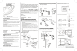
PAC2 Connectors & Indicators (Front View)
1
2
3
5
11
12
13
6
8
9
10
7
4
2
1
PAC2 Connectors (Bottom View)
15
16
17
18
19
14

Professional Automation Control System Crestron PAC2
8 • Professional Automation Control System: PAC2 Operations Guide – Doc. 5941A
Connectors, Controls & Indicators
# CONNECTORS
1
,
CONTROLS &
INDICATORS
DESCRIPTION
1 NET (and LEDs)
(A – H)
24 Y
Z
G
(32) 4-pin 3.5 mm detachable terminal blocks
comprising (4) Cresnet ports (paralleled) per
each of (8) segments
24: Power (24 Vdc)
Y: Data
Z: Data
G: Ground
(8) Yellow LEDs indicate Cresnet
communications on each respective segment
2 LEFT, RIGHT
(2) 5-pin 0.156 inch headers;
Module interconnect ports, connect to
CLX-Series lighting control modules using
included interconnect cables
3 POWER (and LEDs)
(1 - 4)
INT
G
EXT
(4) 3-pin 3.5 mm detachable terminal blocks
comprising (1) Cresnet power selection
connecter per each of (4) power groups;
Connect to external Cresnet power supply or
to internal power supply via jumpers, to
power Cresnet devices connected to the
NET ports;
Maximum load per power group using
external supply: 75 watts (3.125 amps @ 24
Vdc);
Maximum total load using internal supply: 50
watts (2 amps @ 24 Vdc);
(4) Green LEDs indicate 24 Vdc power
present at each respective power group
4 I/O (1 - -8)
1 2 3 4
5 6
7
8
G
(1) 9-pin 3.5 mm detachable terminal block
comprising (8) “Versiports” – digital
input/output or analog input ports;
Digital input: Rated for -024 Vdc; input
impedance 20 kΩ; logic threshold 1.24 Vdc;
Digital output: 250 mA sink from maximum
24 Vdc; catch diodes for use with “real world”
loads;
Analog input: Rated for 0-10 Vdc, protected
to 24 Vdc maximum; input impedance 20 kΩ;
Programmable 5 volts, 2 kΩ pull-up resistor
per pin;
All ports referenced to ground
5 OVERRIDE
R
LG
(1) 3-pin 3.5 mm detachable terminal block
comprising (2) inputs from external contact
closures to trigger the preset override state in
CLX-Series modules connected to the
module interconnect ports;
Maximum input: 1- mA at 5 volts
(Continued on following page)

Crestron PAC2 Professional Automation Control System
Operations Guide – Doc. 5941A Professional Automation Control System: PAC2 • 9
Connectors, Controls & Indicators (Continued)
# CONNECTORS
1
,
CONTROLS &
INDICATORS
DESCRIPTION
6 BACKUP NET INPUT
24 Y
Z G
(1) 4-pin 3.5 mm detachable terminal block
backup Cresnet port;
Connects to the NET port of a backup control
system and power supply
24: Power (24 Vdc)
Y: Data
Z: Data
G: Ground
7 PWR LED (1) Green LED, indicates power supplied to
unit via AC line or BACKUP NET INPUT
8 Reset Buttons
HW-R – Hardware reset (reboots the control
system)
SW-R – Pressing this in combination with
HW-R button performs a system restart
without loading the program. Pressing it
alone momentarily while the system is
running restarts the program
9 NET LED (1) Yellow LED, indicates Cresnet bus
activity
10 ERR LED (1) Red LED, indicates control system has
generated an error message
11 LAN (A – B) LEDS
2
LNK – Indicate the Ethernet card has
established a valid Ethernet connection
ACT – Indicate communication (activity) at
the respective port on the Ethernet card
12 FAULT (and LED)
GF
(1) 2-pin 3.5 mm detachable terminal block;
Contract closure output;
Relay closed when PAC become inactive;
Connects to digital input of backup control
system;
(1) Red LED, indicates PAC2 has become
inactive, FAULT output is active (relay
closed)
13 RELAY OUTPUT
(1 – 8)
1 2 3 4
5 6
7
8
(2) 8-pin 3.5 mm detachable terminal blocks
comprising (8) normally open, isolated
relays;
Rated 1 amp, 30 volts ac/dc;
MOV arc suppression across contacts
14 S3 Z-BUS (1) Z-Bus expansion slot;
Accepts all Z-Bus control cards
15 MEMORY EXPANSION (1) Type II Compact Flash card slot for
memory expansion (up to 4 GB)
16 COMPUTER
(1) DB9 female’
RS-232 computer console port
(Continued on following page)

Professional Automation Control System Crestron PAC2
10 • Professional Automation Control System: PAC2 Operations Guide – Doc. 5941A
Connectors, Controls & Indicators (Continued)
# CONNECTORS
1
,
CONTROLS &
INDICATORS
DESCRIPTION
17 NET
(24 VDC 50W)
24 Y
Z G
24VDC 50W
(1) 4-pin 5 mm detachable terminal block;
Cresnet port, Master/Slave selectable’
Expandable via C2N-NPA8 Network Poll
Accelerator (sold separately)
24: Power (24 Vdc)
Y: Data
Z: Data
G: Ground
18 Line Power
(1) Attached input power cable, ~1 foot (~305
mm) long, with inline IEC320 socket;
Connects to ac power source using
grounded pigtail cable and DIN rail terminal
block (both included)
19 S1, S2 (2) Y-Bus expansion slots;
Accept all Y-Bus control cards
1. Interface connectors for NET, LEFT/RIGHT, POWER, I/O, OVERRIDE, BACKUP NET
INPUT, FAULT, RELAY OUTPUT and NET (24VDC 50W) ports are provided with the unit.
2. LAN LEDs are active only if a single port or dual port Ethernet card (which is field installed)
occupies the Z-Bus slot.
Built-In Cresnet Hub/Repeater
The built-in Cresnet Hub/Repeater serves as a repeater, splitter and wiring block.
The hub allows for 256 or more devices; 32 per segment (A-H) and distribution up to
3000 feet (~914 meters) per segment.
There are eight independent segments, each with four Cresnet connectors wired in
parallel. Each segment has a dedicated driver/receiver for Cresnet communication. In
addition, there is a master NET port on the front panel. The eight NET (A-H)
activity LEDs illuminate when a device on the respective segment transmits data.
Segments that are not in use or have devices that are not polled by a Crestron
Studio™ (or SIMPL Windows) program are logically “disconnected” from the other
segments in operation. The LEDs for these segments are not illuminated.
CAUTION: Use only Crestron power supplies for Crestron equipment. Failure to
do so could cause equipment damage or void the Crestron warranty.
Power for the hub is supplied through POWER ports 1, 2, 3, and 4, to segment pairs,
as shown in the illustration on the following page. When power is applied, the LED
adjacent to the port is illuminated.

Crestron PAC2 Professional Automation Control System
Operations Guide – Doc. 5941A Professional Automation Control System: PAC2 • 11
Powering a Hub Segment Pair
In the illustration above, one of the supplied 3-pin mini connectors with installed
jumper wire is plugged into the POWER 1 port. The PAC 2’s internal power supply
is connected to the INT pin; the port’s EXT pin is connected to the 24 pin of each
connector in the segment pair. Since the jumper connects the INT and EXT pins of
the port, 24Vdc is supplied to each connector and the external network devices.
If the power needed for a hub segment exceeds the power available from the internal
supply (50 watts, maximum), remove the jumper from the supplied 3-pin mini
connector to disconnect the internal power supply, then connect the 24Vdc and
ground wires from an external source (such as a Crestron 24 Vdc regulated power
supply) to the EXT and G pins.
NOTE: If a device or Cresnet network connected to a hub segment has its own
power source, do not make any connection to the applicable POWER port. Although
equipment damage is unlikely, Crestron does not recommend applying two power
sources to the same circuit.

Professional Automation Control System Crestron PAC2
12 • Professional Automation Control System: PAC2 Operations Guide – Doc. 5941A
Setup
Network Wiring
When wiring the Cresnet network, consider the following:
Use Crestron Certified Wire.
Use Crestron power supplies for Crestron equipment.
Provide sufficient power to the system.
CAUTION: Insufficient power can lead to unpredictable results or damage
to the equipment. Use the Crestron Power Calculator to help calculate how
much power is needed for the system (
www.crestron.com/calculators).
For networks with 20 or more devices, use a Cresnet Hub/Repeater (CNXHUB) to
maintain signal quality.
For more details, refer to “Check Network Wiring” which starts on page 23.
Installation
Ventilation
The PAC2 should be used in a well-ventilated area. The venting holes should not be
obstructed under any circumstances.
To prevent overheating, do not operate this product in an area that exceeds the
environmental temperature range listed in the table of specifications. Consider using
forced air ventilation or incrementing the spacing between units to reduce
overheating. Consideration must be given if installed in a closed or multi-unit rack
assembly since the operating ambient temperature of the environment may be greater
than the room ambient temperature. Contact with thermal insulating materials should
be avoided on all sides of the unit.
Mounting in a CAEN
CAUTION: The Crestron Automation Enclosure (CAEN) houses equipment that
needs to be air-cooled. Therefore, mount in a well-ventilated area. The ambient
temperature range must be 41° F to 113° F (5° C to 45° C). The relative humidity
must range from 0% to 90% (non-condensing). Allow adequate clearance in front of
the vented cover for servicing and ventilation.
NOTE: The CAEN is intended for indoor use only.
NOTE: Reliable earth grounding of equipment mounted in a CAEN should be
maintained. Particular attention should be given to supply connections other than
direct connections to the branch circuit (for example, use of power strips).
The PAC2 has two flanges that allow the unit to be mounted in a CAEN. For more
information about the CAEN, refer to the latest version of the CAEN – Automation
Enclosures Installation Guide (Doc. 5940). The following procedure assumes two
CLX-Series modules have been installed in a double-wide CAEN. Complete the
procedure below to attach the PAC2 to the CAEN. A #2 Phillips screwdriver is
required.

Crestron PAC2 Professional Automation Control System
Operations Guide – Doc. 5941A Professional Automation Control System: PAC2 • 13
1. Using a #2 Phillips screwdriver, attach the four supplied self-tapping pan
Phillips screws (8B x 1/4”) by screwing them in partially (to allow room to
mount the PAC2) below the modules. (Refer to the illustration below.)
2. Mount the PAC2 in the CAEN (where the screws were attached in step 1),
slide the unit to the right to ensure the screws fully engage the slots in the
flanges, then tighten the screws.
NOTE: For a single-wide CAEN, attach screws on right (screw them in partially),
mount the PAC2 (where the screws were attached in step 1), attach screws on left
and fully tighten all screws.
Mounting the PAC2 in a CAEN
8B 1/4 inch
screw
CLX-Series Module
PAC2
Double-wide
CAEN
Bussing Strip Installation
The PAC2 is supplied with two brass bussing strips to facilitate commoning
(linking) of the RELAY OUTPUT terminal block connections. The bussing strips
are constructed with four terminal block positions, and may be trimmed to size for
various applications or different devices. One strip is supplied for each 8-position
terminal block.
1. To utilize the bussing strip, determine the number of relays to be commoned
for the equipment being installed. If less than four, the strip can be trimmed
to size with a pair of scissors or wire snips.

Professional Automation Control System Crestron PAC2
14 • Professional Automation Control System: PAC2 Operations Guide – Doc. 5941A
2. Loosen the terminal block screws and insert the first leg of the bussing strip
into the first common position on the terminal block. The strip engages the
other common positions automatically.
3. Remove approximately 1/8” of the jacket from the common wire and insert
the conductor into one of the terminal block common positions. Tighten the
terminal block screws to lock the wire and bussing strip into place. Insulate
the strip by folding a piece of 3/4” wide vinyl electrical tape over the spine
and as much of the individual legs as possible. Excess tape at each end of
the strip should be pressed closed, then trimmed to within approximately
1/16” of the end of the strip.
4. When wiring the remaining conductors, remove approximately 1/8” of the
jacket and insert the wires into the proper terminal block positions. To
prevent the possibility of electrical shorts, it is essential that these
conductors do not touch any uninsulated portion of the bussing strip.
5. Secure the wires connected to the terminal block with a tie wrap around the
bussing strip to provide strain relief.
Hardware Hookup
Make the necessary connections as called out in the illustrations on the following
page. Refer to “Network Wiring” on page 12 before attaching the 4-position terminal
block connectors. Apply power after all connections have been made.
When making connections to the PAC2, use Crestron power supplies for Crestron
equipment.

Crestron PAC2 Professional Automation Control System
Operations Guide – Doc. 5941A Professional Automation Control System: PAC2 • 15
Hardware Connections for the PAC2 (Front)
LEFT:
To CLX-Series Module
(for Single and
Double-Wide CAEN)
POWER:
24 Vdc to Hub
from Internal
or External Power
RIGHT:
To CLX-Series Module
(for Double-Wide CAEN)
NET:
To Cresnet
Network Devices
RELAY OUTPUT:
To controllable devices
I/O:
To Controllable Devices
From Device Outputs
-Contact Closures
-Solid State Closures
OVERRIDE:
To Override Switch
FAULT:
To control system
(I/O port)
BACKUP NET INPUT:
To Control System
for Backup Cresnet Power
NET:
To Cresnet
Network Devices
Hardware Connections for the PAC2 (Bottom)
MEMORY EXPANSION:
For Optional
Compact Flash Memory Card
COMPUTER:
To Serial Port on PC
Using DB9 RS-232 Cable
NET:
To Any Cresnet Device
Line Power:
From AC
Power Source

Professional Automation Control System Crestron PAC2
16 • Professional Automation Control System: PAC2 Operations Guide – Doc. 5941A
NOTE: Ensure the unit is properly grounded by connecting the chassis ground lug
to an earth ground (building steel).
NOTE: To prevent overheating, do not operate this product in an area that exceeds
the environmental temperature range listed in the table of specifications.
NOTE: Since the plug on the power supply cord is used to disconnect power from
the unit, the socket-outlet shall be installed near the equipment and shall be easily
accessible.
AC Power Connection
The PAC2 requires ac power for operation. This can be accomplished using the
materials listed in the following table. This involves adding the terminal blocks and
associated parts to the lower left terminal rail in a double-wide CAEN enclosure, or
the lower terminal rail in a single-wide enclosure, and making the necessary wiring
connections. The power cable and hardware required for connection are supplied
with the PAC2.
Supplied Parts for PAC2 AC Connection
QUANTITY/DESCRIPTION PART #
One (1) White, 1-Position Terminal Block JTTB01-4
One (1) Black, 1-Position Terminal Block JTTB01-6
One (1) Terminal Block Partition Plate JTHWXX-3
One (1) Terminal Block End Plate JTHWXX-2
One (1) Terminal Block End Bracket JTHHXW-1
One (1) Power Cord CAXXIPC-65008A-1
Refer to the illustration on the following page and perform the associated procedures.
WARNING: Verify ac power to the CAEN assembly is turned off before
performing any of these assembly or wiring procedures.
/