
SAVE THIS BOOK
This book is valuable. In addition to instructing you
on how to install and maintain your appliance, it also
contains information that will enable you to obtain re-
placement parts or accessory items when needed. Keep
it with your other important papers.
ANS Z21.60, Z21.84 or RGA 2-72 standards or for use
with a vent-free gas log heater approved to ANS Z21.11.2
standard.
etc.) should be contacted before installation to deter-
mine the need to obtain a permit.
36" WOOD BURNING MASONRY FIREPLACE
OWNER’S OPERATION AND INSTALLATION MANUAL
and Herringbone Refractory
For more information, visit www.desatech.com
ICC-ES #ESR-2542

www.desatech.com
116010-01E2
-
damage or loss of life. Refer to this manual for assis-
installer or local distributor.
TABLE OF CONTENTS
Safety .................................................................. 2
Specications ...................................................... 3
Fireplace Installation............................................ 4
Venting Installation .............................................. 6
Optional Gas Line Installation............................ 10
Glass Door Installation ...................................... 12
Operation and Maintenance Guidelines ............ 13
Replacement Parts ............................................ 14
Technical Service............................................... 15
Accessories ....................................................... 15
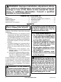
SAFETY
Before beginning the installation of the
fireplace, read these instructions through
completely.
• This DESA Heating, LLC replace and its
components are safe when installed ac-
cording to this installation manual. Unless
you use DESA Heating, LLC components,
which have been designed and tested for
the replace system, you may cause a re
hazard.
• The DESA Heating, LLC warranty will be
voided by and DESA Heating, LLC dis-
claims any responsibility for the following
actions.
a. Modification of the fireplace, com-
ponents, doors, air inlet system and
damper control.
b. Use of any component part not manu-
factured or approved by DESA Heat-
ing, LLC in combination with a DESA
Heating, LLC replace system.
Proper installation is the most important step
in ensuring safe and continuous operation
of the replace. Consult the local building
codes as to the particular requirements
concerned with the installation of all factory
built replaces.
-
less the manufacturer's instruc-
tested for use with the insert.
used as a substitute for a furnace
supplemental heat only.
or liquids in the vicinity of this
or any other appliance.
appliance should be located
furniture and draperies.
the appliance.
-
logs are used, do not poke or stir
the logs while they are burning.
evaluated for the application in
warnings and caution markings
on packaging prior to use.

www.desatech.com
116010-01E 3
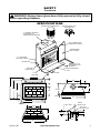
SPECIFICATIONS
10.5"
15.375"
0.625"
45"
29"
26.625"
22"
36"
21.5"
3.5"
10.75"
1"
49"
8"
58"
30"
36"
45"
12"
9.5"
7"
67"
7.5"
1
1
/
2
" AIR SPACE
BACK AND SIDES
0" TO
BOTTOM
GAS LINE
KNOCKOUTS
12" EACH SIDE
COMBUSTIBLE
WALL BOARD
NO COMBUSTIBLE
MATERIAL ON FACE
MINIMUM 12" TO
PERPENDICULAR
SIDEWALL
HEARTH EXTENSION
74" X 20"
1" CHIMNEY AIRSPACE
CLEARANCE TO
COMBUSTIBLE MATERIAL
TERMINATION
SQUARE CHASE-TOP
ROUND TOP TERMINATION
OUTSIDE AIR
20"
GAS LINE
KNOCK OUTS
AIR KIT
KNOCK OUT
LEFT SIDE
SAFETY
Continued

www.desatech.com
116010-01E4
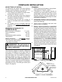
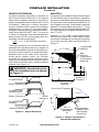
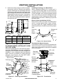
FIREPLACE INSTALLATION
To determine the safest and most efcient
location for the replace, you must take into
consideration the following guidelines:
1. The location must allow for proper clear-
ances (see Figures 1 and 2).
2. Consider a location where the replace
will not be affected by drafts, air condition-
ing ducts, windows or doors.
3. A location that avoids the cutting of
joists or roof rafters will make installation
easier.
4. An outside air kit is available with this
replace (see Optional Outside Air Kit,
page 6).
Back and sides of replace 1
1
/
2
" min.*
Front of replace 48" min.
Floor** 0" min.
Perpendicular wall to opening 12" min.
Top spacers 0" min.
Mantel clearance
see Mantels, page 5
Chimney outer pipe surface 1" min.
* Not required at nailing anges
** See step 2 of Framing
-
quired air spaces with insulation
or other materials.
The minimum height of chimney, measured
from base of replace to ue gas outlet of
termination, is 16 feet for straight ue or a ue
with one elbow set. The maximum distance
between elbows is 6 feet. For systems with
two elbow sets, the minimum height is 22
feet. The maximum height of any system is
50 feet. This measurement includes replace,
chimney sections and height of termination
assembly at level of the ue gas outlet (see
Figure 15, page 9).
28.25"
58.125"
67.125"
45.25"
Figure 1 - Framing Dimensions
86.5"
61"
Maintain 1
1
/
2
"
Clearance at Sides
and Back of Fireplace
1
1
/
2
" Clearance
Not Required at
Nailing Flanges
Figure 2 - Corner Installation
1. Frame opening for replace using dimen-
sions shown in Figures 1 and 2.
2. If replace is to be installed directly on
carpeting, tile (other than ceramic) or any
combustible material other than wood
ooring, replace must be installed on a
metal or wood panel extending full width
and depth of replace.
3. Set replace directly in front of this open-
ing and slide unit back until nailing anges
touch side framing.
4. Check level of replace and shim with
sheet metal if necessary.
5. Before securing fireplace to prepared
framing, ember protector (provided) must
be placed between hearth extension (not
supplied) and under bottom front edge of
replace to protect against glowing embers
falling through. If replace is to be installed
on a raised platform, a Z-type ember pro-
tector (not supplied) must be fabricated to
t your required platform height. The ember
protector should extend under the replace
a minimum of 1
1
/
2
". The ember protector
should be made of galvanized sheet metal
(28 gauge minimum to prevent corrosion.
6. Using screws or nails, secure replace to
framing through anges located on sides
of replace.

www.desatech.com
116010-01E 5
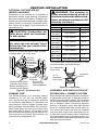
HEARTH ExTENSION
A hearth extension projecting a minimum of
20" in front of and a minimum of 12" beyond
each side of replace opening is required to
protect combustible oor construction in front
of replace. Fabricate a hearth extension
using a material which meets the following
specications: a layer of noncombustible,
inorganic material having a thermal conduc-
tivity of K=0.84 BTU IN/FT, HR. F (or less) at
1" thick. For example, if the material selected
has a K factor of 0.25, such as glass ber, the
following formula would apply:
0.25 x 1.0" = 0.30" thickness required
0.84
Thermal conductivity "K" of materials can be
obtained from the manufacturer or supplier of
the noncombustible material. If the hearth ex-
tension is to be covered, use noncombustible
material such as tile, slate, brick, concrete,
metal, glass, marble, stone, etc. Provide
a means to prevent hearth extension from
shifting and seal gap between replace frame
and hearth extension with a noncombustible
material (see Figure 3).
is to be installed only as shown
FIREPLACE INSTALLATION
Continued
Figure 3 - Hearth Extension
Seal Gap
Fireplace Front
Ember Protector
Fireplace Front
Raised Hearth
Fireplace Front
Elevated
Ember Protector
Ember Protector
Seal Gap
Hearth
Extension
A mantel may be installed if desired (see Figure
4). Woodwork such as wood trims, mantels or
any other combustible material projecting from
the front face must not be placed within 12" of
the replace opening. Combustible materials
above 12" and projecting more than 1
1
/
2
" from
the replace must not be placed less than 15"
from top opening of replace (NFPA STD 211,
Sec. 7-3.3.3).
Mantels or any other combustible mate-
rial also may come up to side edge of black
metal face of replace as long as projection
from front face fall within the limit shown in
Figure 4.
12
1
/
4
" Ref.
15" Min.
12" Min.
1
1
/
2
" Max.
3" Nom.
33°
Combustible
Material
Safe
Zone for
Projection of
Combustible
Materials
Fireplace
Opening
Upper
Section of
Fireplace
Figure 4 - Mantel Clearances to
Combustible Material
FIREBOX
SAFE ZONE
Top View of Fireplace
3" Max.
4.5"
Min. to
Perpendicular
Side Wall
12"
7.75"
33°
Combustible
Material Must
Not Overlap
Front Face
6"
Ref.

www.desatech.com
116010-01E6
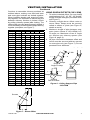
Figure 6 - Lineal Gain
PART NO. GAIN
Georgian Fireplace 66
1
/
2
"
12-12DM
12-12HT
Pipe Section 10
5
/
8
"
18-12DM
18-12HT
Pipe Section 16
5
/
8
"
24-12DM
24-12HT
Pipe Section 23
5
/
8
"
36-12DM
36-12HT
Pipe Section 34
5
/
8
"
48-12DM
48-12HT
Pipe Section 46
5
/
8
"
RLT-12D
RLT-12HT
Round Termination 7
3
/
4
"
*
STL-12D
Square Chase-Top
with Slip Section
7
"
to 15
"
*
* The lineal gain for the terminations is mea-
sured to the ue gas outlet height.
Hemmed
End
12
3
/
8
"
Stainless
Inner Pipe
15" Galvanized
Outer Pipe
The DESA Heating, LLC chimney system
consists of 12", 18", 24", 36" and 48" snap-
lock, double-wall pipe segments, planned
for maximum adaptability to individual site
requirements. Actual lengths gained after
tting overlaps must be taken into consider-
ation (lineal gain) and are given in the lineal
gain chart (see Figure 6). Lineal Gain is the
actual measurable length of a part after two or
more parts are connected. For Canada, use
chimney parts designated "HT".
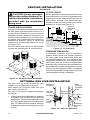
VENTING INSTALLATION
Figure 5 - Outside Air Kit
Secure to Collars with Metal Tape, Screws
or Straps (Min. 1/4" x 20" size)
Air Inlet
Location
Must Allow
For Bushes
or Snow
Vent Hood
Required for
Wall Installation
Air Inlet
Eyebrow
Vented Crawl Space
(Check Local Codes
Before Installing in a
Vented Crawl Space)
Installation of an outside air kit should be
performed during rough framing of replace
due to the nature of it's location. Outside com-
bustion air is accessed through a vented crawl
space (AK4F) or through a sidewall (AK4).
See Figure 26 on page 14 for instruction of
operating air kit.
inlet ducts shall not terminate
in attic space.
termination.
Each double wall chimney section consists of
a galvanized outer pipe, a stainless steel in-
ner ue pipe and a wire spacer. Pipe sections
must be assembled independently as chim-
ney is installed. When connecting chimney
directly to replace, inner ue pipe section
must be installed rst with lanced side up.
The outer pipe section can then be installed
over ue pipe section with hemmed end up.
Press down on each pipe section until lances
securely engage hem on replace starter. The
wire will assure proper spacing between inner
and outer pipe sections.
collar around chimney at top of
chimney enclosure.

www.desatech.com
116010-01E 7
VENTING INSTALLATION
Continued
Continue to assemble chimney sections as
outlined above, making sure that both inner
and outer pipe sections are locked together.
When installing double wall snap-lock chim-
ney together, it is important to assure the joint
between chimney sections is locked. Check
by pulling chimney upward after locking. The
chimney will not come apart if properly locked. It
is not necessary to add screws to keep chimney
together (exception, see Figure 7).
OFFSET CHART (22-50 FT. SYSTEM HEIGHT)
Figure 8 - Ceiling Support Pipe
12S-12DM
2" Min.
Straps
Straps
Straps
Straps
Detail A
Return Elbow
Detail B
Angle Firestop
See Detail A
See Detail B
1. To achieve desired offset, you may install
combinations of 12", 18", 24", 36" and 48"
length of double wall pipe (see offset chart
and Figure 7).
2. Chimney weight above offset rests on
return elbow. Straps must be securely
nailed to rafters or joists (see Figure 8,
details a and b).
3. Maximum length of pipe between sup-
ports (return elbow or 12S-12DM) is 6'
of angle run. Maximum of two 6' angle
run sections per chimney system (see
Figure 9, page 8).
4. All pipe connections between offset and
return must be secured with two screws
on outer pipe only (see Figure 7). Do not
penetrate inner stainless.
RISE
A B 12" 18" 24" 48"
4
3
/
8
" 16
3
/
8
"
ELBOW SET ONLY
9
3
/
4
" 25
1
/
2
"
1
12
3
/
4
" 30
3
/
4
"
1
15" 34
3
/
4
"
1
18" 40"
1 1
21
1
/
4
" 46
1
/
4
"
1
23
3
/
4
" 49
1
/
4
"
1 1
27
3
/
4
" 56
3
/
4
"
1
30" 60
3
/
4
"
1 1
33" 66"
1 1
36" 71"
1 1
38
1
/
4
" 75"
2
41
1
/
4
" 80
1
/
4
"
1 1 1
45" 86
3
/
4
"
2
46
3
/
4
" 89
1
/
2
"
1 1 1
51" 97"
1 1
53
1
/
4
" 101"
1 2
56
1
/
4
" 106
1
/
4
"
2
59
1
/
4
" 111
1
/
2
"
1 1 1
61
3
/
4
" 115
1
/
2
"
1 2
64
3
/
4
" 120
3
/
4
"
1 2
68
1
/
4
" 127"
2 1
70" 130"
1 1 2
74
1
/
4
" 137
1
/
2
"
1 2 1
76
3
/
4
" 141
1
/
2
"
1 2 1
79
3
/
4
" 146
3
/
4
"
4
Figure 7 - Elbow Offset
B
A
Screws

www.desatech.com
116010-01E8
VENTING INSTALLATION
Continued
Firestop spacers are required at each point
where chimney penetrates a floor space.
Their purpose is to establish and maintain
required clearance between chimney and
combustible materials. When pipe passes
through a framed opening into a living space
above, restop must be placed onto ceiling
from below as shown in Figure 10.
They also provide complete separation from
one oor space to another or attic space as
required by most codes. When double wall
pipe passes through a framed opening into
an attic space, restop must be placed into
attic oor as shown in Figure 11.
Figure 10 - Firestop Spacer with Living
Space Above Ceiling
Figure 11 - Firestop Spacer with Attic
Space Above Ceiling
Existing
Ceiling
Frame
Firestop
Spacer
Screws or
Staples
(Min. of 8)
Firestop
Spacer
Screws or Staples
(Min. of 8)
To maintain a 1" clearance to the pipe on a
roof with a pitch, a rectangular opening must
be cut.
1. Determine the center point through which
pipe will penetrate the roof.
2. Determine center point of the roof. Pitch
is the distance the roof drops over a given
span, usually 12". A 6/12 pitch means the
roof drops 6" for each 12" one measure
horizontally down from roof rafters.
3. Use roof opening chart (Figure 12, page
9) to determine correct opening length and
ashing required.
4. Remove shingles around opening mea-
sured. Cut out this section.
Existing
Ceiling
Frame
Figure 9 - Typical Offset Terminations
Return
Elbow
Offset
Elbow
Return
Elbow
Offset
Elbow
6' Max.
6' Max.
6' Max.
6' Max.
6' Max.
6' Max.
Return
Elbow
Offset
Elbow
Offset
Elbow
Return
Elbow
A B C
Offset
Elbow
Ceiling
Support Pipe
12S-12DM
Return
Elbow

www.desatech.com
116010-01E 9
VENTING INSTALLATION
Continued
17" Min.
30" Min.
1" Min.
1" Min.
1" Min.
Opening "A"
Pitch Slope Opening
Flat 0° 17" V6F-10DM
0-6/12 26.6° 19" V6F-10DM
6/12-
12/12
45.0° 24" V12F-10DM
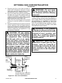
5. Add next sections of pipe until the end pen-
etrates the roof line. Check to see that the
proper clearances are maintained. Extend
chimney by adding sections of double wall
pipe until pipe is minimum of 30" above the
highest point of the roof cutout. Termination
and chimney must extend a minimum of
36" above the highest point where it passes
through the roof.
Figure 12 - Roof Opening Measurements
Nail Only
Outer
Perimeter
of Flashing
Storm Collar
Flashing Cone
Underlap Shingles
at Bottom
Overlap
Shingles Top
and Sides Only
Figure 13 - Flashing Installation
Determine ashing to be used with roof open-
ing chart. Slide ashing over pipe until base is
at against roof. Replace as many shingles as
needed to cover exposed area and ashing
base. Secure in position by nailing through
shingles (see Figure 13). DO NOT NAIL
THROUGH FLASHING CONE.
Figure 14 - Storm Collar
Chimney
Pipe
Waterproof
Caulk
Storm
Collar
Flashing
When installing ashing on a metal roof, it
is required that putty tape be used between
ashing and roof. Flashing must be secured
to roof using #8 x 3/4" screws and then sealed
with roof coating to prevent leakage through
screw holes. A roof coating must also be ap-
plied around perimeter of ashing to provide
a proper seal.
Place storm collar over pipe and slide down
until it is snug against open edge of ash-
ing (see Figure 14). Apply waterproof caulk
around perimeter of collar to provide a proper
seal.
Terminations/Spark Arrestor
The replace system must be terminated with
listed round top or chase terminations. In any
case, refer to installation instructions supplied
with termination.
Secure
Termination
to Outer
Pipe with 3
Screws
RTL-10D
Level of
Flue Gas
Outlet
Stainless
Inner Flue
Pipe
Waterproof
Caulking
Storm
Collar
Flashing
Underlap
Shingles
Figure 15 - Termination
Overlap
Shingles (Top
and Sides of
Flashing Base)

www.desatech.com
116010-01E10
VENTING INSTALLATION
Continued
All ue gas outlet chimney terminations must
extend a minimum of 3 feet in height above the
highest point where it passes through the roof
and must be at least 2 feet above the high-
est point of the roof that is within a horizontal
distance of 10 feet (see Figure 17).
Combustible materials, such as wallboard,
gypsum board, sheet rock, drywall, plywood,
etc. may make direct contact with sides and
top around replace face. It is important that
combustible materials do not overlap the face
itself. Brick, glass, tile or other noncombustible
materials may overlap front face provided they
do not obstruct essential openings like louvered
slots or any other opening. When overlapping
with a noncombustible facing material, use only
noncombustible mortar or adhesive.
24" Min.
24" Min.
18"
Min.
Typ.
Figure 16 - Multiple Chase Installation
10'
2' Min.
10'
3' Min.
2' Min.
3' Min.
Level of
Flue Gas
Outlet
Figure 17 - 10 Foot Rule
Figure 18 - Gas Line Knockout
Side
Firebrick
Finished
Side
Refractory
Knockout
Plug
Outside of
Fireplace
Gas Line
Conduit
Insulation
Gas
Conduit
Cover
1/2" Dowel
Remove
Knockout
OPTIONAL GAS LINE INSTALLATION
-
-
low the installation instructions
provided with the termination
being used.
Instructions for chase installations are includ-
ed with chase style termination chosen. In a
multiple chase installation, be sure to provide
adequate distance between terminations to
prevent smoke spillage from one termination
to another. We suggest that terminations be
separated at least 24" center to center and
stacked at a vertical height difference of 18"
(see Figure 16).
Note: If a decorative shroud is to be installed,
contact the manufacturer for specications.
Gas line hook up should be done by your
supplier or a qualied service person.
Note: Before you proceed, make sure your
gas supply is turned off.
Use only a 1/2" black iron pipe and appropri-
ate ttings.
1. Remove knockout indentation on refractory
or rebrick wall located above refractory
hearth oor. The knockout indentation must
be rmly tapped with any solid object such
as a 1/2" dowel until it is released. Remove
fragmented portions of refractory (see Fig-
ure 18).

www.desatech.com
116010-01E 11
2. Remove gas line cover plate located on
either side of replace and pull out insu-
lation from gas line conduit sleeve. Save
insulation for reuse. Replace screws.
3. Run a 1/2" black iron gas line into replace
through rear at gas line conduit sleeve (if
using a raised platform, add height). Provide
sufcient gas line into replace chamber for
tting connection (see Figure 19).
Note: Secure incoming gas line to wood
framing to provide rigidity for threaded
end.
4. Repack insulation around gas line and into
sleeve opening. Seal any gaps between
gas line and refractory knockout hole with
refractory cement or commercial furnace
cement, Install the gas appliance or cap
off gas line if desired.
and connections must be tested
for leaks after the installation
is completed. After ensuring
that the gas valve is on, apply
soap and water solution to all
forming show a leak. Correct
-
-
Seal
Opening
with
Refractory
Cement
Outside of
Fireplace
Gas
Line
Conduit
Repack
Insulation
Incoming
1/2" Black
Iron Pipe
Side
Firebrick
Finished
Side
Provide Enough Threaded
End for Fitting Connection
Figure 19 - Gas Line Installation
OPTIONAL GAS LINE INSTALLATION
Continued
-
ate an unvented gas log set in
removed.
If you install a decorative gas appliance
(vented gas log), the decorative gas appliance
must comply with the Standard for Decorative
Gas Appliance for Installation in Solid Fuel
Burning Fireplaces, ANS Z21.60, Z21.84 or
RG 2-72 and shall also be installed in accor-
dance with the National Fuel Gas Code, ANSI
7223NFPA 54 latest edition.
has been used for wood burning,
cleaned of soot, creosote and
cleaner. Creosote will ignite if
heavily heated.
decorative vented gas log, the
damper must be removed or
permanently locked in the fully
open position and the glass
doors must be in the fully open
position.

www.desatech.com
116010-01E12
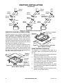
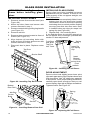
GLASS DOOR INSTALLATION
Figure 20 - Installing Top Door Frame
Top Door
Rail
Smoke Shelf
frame before installing glass
door.
1. Remove screws from smoke shelf (see
Figure 20).
2. Mount top door frame and secure with
screws removed in step 1.
3. Remove center brick by pulling ring handle
(see Figure 21).
4. Remove ash box.
5. Remove three screws located at front of
rebox (see Figure 21).
6. Align bottom rail mounting holes with
holes at front of rebox and secure with
screws removed in step 5.
7. Place ash box in place. Replace center
brick.
Remove doors and slightly loosen lower pivot
clips and upper spring clips. Replace doors and
fully close them. Use 1/8" shims (any material)
to level doors. Once proper setting is achieved,
carefully open doors enough so that you can
access spring clips with a phillips screwdriver.
Tighten screws. See Figure 23.
Figure 22 - Installing Bi-Fold Doors
Spring
Clip
Insert Pin
into Spring
Clip
Pivot
Hole
Insert
Bottom
Pivot Pin
into Hole
Fold Door
and Slide
Top Pins
Into Track
Figure 23 - Adjusting Bi-Fold Doors
Figure 21 - Installing Bottom Door Rail
Bottom
Door Rail
Ash Box
Center
Brick
Ring
Handle
Screws
Spring clips have been installed but some
adjustments may be needed. If doors do not
close properly or do not appear straight, see
Door Adjustment.
1. With bi-fold doors completely folded, insert
bottom pivot pin into pivot hole located
near bottom corner of front face opening
and swing door to vertical position making
sure top pins slide into door track. Door
is installed when top door pin snaps into
spring clip (see Figure 22).
2. Repeat step 1 for remaining door.
If you nd the doors do not close properly or
do not appear level or straight, proceed with
section on door adjustment.
Spring
Clip

www.desatech.com
116010-01E 13
Figure 24 - Bi-Fold Glass Doors
Doors Fully Closed
Fireplace Front
Fireplace Front
Doors
Fully Opened
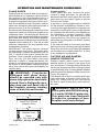
OPERATION AND MAINTENANCE GUIDELINES
Glass doors are optional with this replace.
When replace is in operation, doors must be
fully opened or fully closed position only or a
re hazard may be created (see Figure 24).
A replace equipped with glass doors oper-
ates much differently than a replace with an
open front. A replace with glass doors has a
limited amount of air for combustion.
Excessive heat within replace can result if too
large a re is built or if combustion air gate is not
completely open. The following tips should be
followed to assure that both replace and glass
door retain their beauty and function properly.
Both ue damper and glass doors must be fully
opened before starting re. This will provide
sufcient combustion air and maintain safe
temperatures in rebox.
IMPORTANT: The glass must be allowed
to warm slowly and evenly. Tempered glass
will withstand a gradual temperature rise to
550° F, which is more than a normal re will
generate. Such materials as pitch/wax laden
logs, very dry mill end lumber and large
amounts of paper or cardboard boxes can
create an excessively hot re and should not
be burned in this replace. Always keep re
away from doors and never allow ames to
contact glass.
equipped with glass doors
should be operated only with
doors fully opened or doors fully
Cleaning Glass
Clean glass with any commercial glass
cleaner or soap and water. Do not use any
abrasive material to clean glass. Do not clean
glass with any cool water if glass is still hot
from re and smoke.
A gas line or gas log lighter may be installed
for the purpose of installing a vented or vent-
free decorative gas appliance incorporating an
automatic shutoff device and complying with
the Standard for Decorative Gas Appliances
for Installation in Vented Fireplaces, ANSI
Z21.60 or American Gas Association draft
requirements for Gas Fired Log Lighters for
Wood Burning Fireplaces, Draft NO. 4 dated
August, 1993.
If you wish to install an unvented (vent-free)
gas log set, only unvented gas log sets which
have been found to comply with the standard
for unvented room heaters, ANSI Z21.11.2 are
to be installed in this replace.
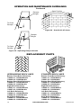
Damper handle, which opens and closes
damper blade, is located in the upper front
face of replace. Pushing handle forward and
up through keyway slot will free damper blade
to automatically open. Pushing handle forward
and down will lock damper blade closed (see
Figure 25, page 14).
The outside air kit lever is located at left and
right hand sides of replace (see Figure 26,
page 14). Lifting lever up will free outside
air door to open. Pulling lever down will lock
the door.
-
This grate has been designed
to keep the operation of your

www.desatech.com
116010-01E14
OPERATION AND MAINTENANCE GUIDELINES
Continued
Figure 25 - Operating Damper Handle
Damper
Weight
To Close
Damper
To Open
Damper
Damper
Weight
Open Position
Closed Position
Figure 26 - Outside Air Kit Lever
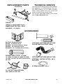
REPLACEMENT PARTS
Bottom Rear Brick Refractory
Right Brick Refractory
Rear Brick Refractory
Bottom Rear Brick Refractory
Right Brick Refractory
Rear Brick Refractory

www.desatech.com
116010-01E 15
GRATE
TECHNICAL SERVICE
You may have further questions about installa-
tion, operation, or troubleshooting. If so, con-
tact DESA Heating, LLC at 1-866-672-6040.
When calling please have your model and
serial numbers of your heater ready.
You can also visit DESA Heating, LLC’s web
site at www.desatech.com.
REPLACEMENT PARTS
Continued
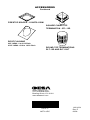
ACCESSORIES
48-12HT
PN 01576

DESA Heating, LLC
2701 Industrial Drive
Bowling Green, KY 42101
www.desatech.com
NOT A UPC
116010-01
Rev. E
06/08
ACCESSORIES
Continued
116010 01
-
 1
1
-
 2
2
-
 3
3
-
 4
4
-
 5
5
-
 6
6
-
 7
7
-
 8
8
-
 9
9
-
 10
10
-
 11
11
-
 12
12
-
 13
13
-
 14
14
-
 15
15
-
 16
16


Ask a question and I''ll find the answer in the document
Finding information in a document is now easier with AI
Related papers
Other documents
-
Gibraltar Building Products 05152 Operating instructions
-
Builders Edge 120033030034 Installation guide
-
Builders Edge 120140806001 Installation guide
-
Gibraltar Building Products PRCS4WG Operating instructions
-
-
FMI BDG42PB Operating instructions
-
Construction Metals JV428 Installation guide
-
-
Builders Edge 120081422001 Installation guide
-