Market Forge ETP-10G Operating instructions
- Category
- Cookers
- Type
- Operating instructions

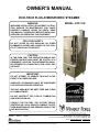
OWNER’S MANUAL
ECO-TECH PLUS ATMOSPHERiC STEAMER
35 Garvey Street • Everett • MA • 02149-4403
Tel: (617) 387-4100 • Toll Free: (866) 698-3188
Fax: (617) 387-4456 (MA and Overseas) • Fax: (800) 227-2659 (Ex. MA)
E-mail: custserv@mi.com • www.mi.com
It is our policy to build equipment which is design certied by A.G.A./C.G.A. and N.S.F. However, a continuing program of product improvement makes it necessary to submit new models to the
agencies as they are developed and consequently not all models bear the appropriate agency labels at all times.
S-6501 Rev. A 05/07
WARNiNG:
iMPROPER iNSTALLATiON, ADJUSTMENT, ALTERA-
TiON, SERViCE OR MAiNTENANCE CAN CAUSE
PROPERTY DAMAGE, iNJURY OR DEATH. READ
THiS MANUAL THOROUGHLY BEFORE iNSTALLiNG,
SERViCiNG OR OPERATiNG THiS EQUiPMENT.
FOR YOUR SAFETY:
DO NOT STORE OR USE GASOLiNE OR OTHER
FLAMMABLE VAPORS AND LiQUiDS iN THE ViCiN-
iTY OF THiS OR ANY OTHER UNiT.
CAUTiON:
iN THE EVEN THAT THE OPERATOR SMELLS GAS
PROPER iNSTRUCTiONS MUST BE POSTED iN A
PROMiNENT LOCATiON. THiS iNFORMATiON SHALL
BE OBTAiNED BY CONSULTiNG YOUR LOCAL GAS
SUPPLiER.
iMPORTANT:
DO NOT ATTEMPT TO OPERATE THiS UNiT iN THE
EVENT OF A POWER FAiLURE.
ADEQUATE CLEARANCES MUST BE MAiNTAiNED
FOR SAFE AND PROPER OPERATiON.
THE UNiT AREA MUST BE KEPT FREE AND CLEAR
OF COMBUSTiBLES.
DO NOT OBSTRUCT THE FLOW OF COMBUSTiON
AND VENTiLATiON AiR.
CONTACT THE FACTORY, THE FACTORY REPRE-
SENTATiVE OR LOCAL SERViCE COMPANY TO PRE-
FORM MAiNTENANCE AND REPAiRS SHOULD THE
UNiT MALFUNCTiON.
MODEL: ETP-10G

i
TABLE OF CONTENTS
PERFORMANCE CHECK:
WARNiNG: THE STEAMER AND iTS PARTS ARE
HOT. USE CARE WHEN OPERATiNG, CLEANiNG
OR SERViCiNG THE STEAMER. THE COOKiNG
COMPARTMENT CONTAiNS LiVE STEAM. STAY
CLEAR WHiLE OPENiNG DOOR.
Once the steamer is installed and all mechanical
connections have been made, thoroughly test the
steamer before operation.
Check that proper water, drain and electrical
and gas connections have been made.
Turn main power switch ON. After approximate-
ly 10 minutes, the “READY” light should come
on, indicating that the water temperature is ap-
proximately 200° Fahrenheit (93° Celsius).
Check that “Ignition” light comes on when the
burner pilot is ON.
1.
2.
3.
When the “READY” light comes on, set timer
to the “5 minute” position. With door open, ob-
serve that no steam is entering the compart-
ment and that the “COOKING” light is OFF.
Close compartment door. The COOKING light
should now be illuminated and steam should be
heard entering the compartment after about 45
seconds.
The tempering tank does not discharge to drain
until the water in the top of the tank reaches
130°F or the unit is shut off and the generators
are allowed to drain.
Open compartment door and observe that
steam supply to chamber is cut off. “READY”
light should again come on as “COOKING” light
goes “OFF”.
Close compartment door and let cooking cycle
nish. When the timer returns to “0”
4.
5.
6.
7.
8.
iNTRODUCTiON
INTRODUCTION ................................................... i
INSTALLATION ......................................................1
OPERATION ..........................................................3
MAINTENANCE .....................................................7
TROUBLE-SHOOTING ..........................................9
ILLUSTRATED PARTS LIST ..................................13

iNTRODUCTiON
DESCRiPTiON:
The Eco-Tech Plus Atmospheric Steamer from
Market Forge Industries is a stainless steel
atmospheric steamer with two cooking com-
partments, each with an independent close-
coupled atmospheric 42,000 BTU gas steam
generator.
Benets: The Eco-Tech Plus incorporates a
water management system that reduces the
amount of water used to condense generated
steam, resulting in substantial savings on en-
ergy-related costs.
Industry First!: The ETP-10G is the only At-
mospheric Twin Generator Steamer that comes
complete with a self contained water lter sys-
tem. The built-in system eliminates the hassle
of where to put the lter and also provides a
warning indicator when it is time to change the
cartridges.
The Energy Star rating may qualify for rebates
in your state. Consult your local utility company
for details.
Construction: Eco-Tech Plus cooking com-
partments and cabinet are stainless steel with
unitized body construction. Cooking compart-
ments have removable left, right, and rear body
panels. Each cooking compartment has a posi-
tive, fully insulated, slam-action door construct-
ed of Type 300 stainless steel. Door gasket is a
one-piece, NSF Approved silicone rubber gas-
ket mounted on the inside of the door. Com-
partments are equipped with door interlock
switches that automatically cut off power to the
gas valve when the doors are opened.
TECHNiCAL SPECiFiCATiONS:
Cooking Compartment: Each compartment is
provided with stainless steel pan support racks
and a stainless steel liner. The front edge of the
bottom compartment contains a condensate
drip trough that drains automatically to a water
management tempering tank.
Controls: Each compartment is individually
controlled by an on/off power switch and 60-
minute electromechanical timer. At the end of
the cooking time, a continuous signal will sound
which can be silenced by returning the timer
to the off position. An exclusive mode selec-
tor gives the operator the option of using each
cooking cavity as a holding cabinet.
Operation: Each compartment utilizes a pow-
erful close-coupled 42,000 BTU steam genera-
tor that supplies steam to the cooking compart-
ments. Generators are held in the “ready” mode
for quick response for heavy-demand situa-
tions. Each generator is rated at 42,000 BTU.
Generator chambers are mounted at the rear
of the steamer cavity and close-coupled to the
steam compartment. Generators include as
standard a pilotless ignition system, automat-
ic water level control, low-water cutoff, safety
relief valve, and preheat thermostat (190°F)
and high limit. Each generator includes an ac-
cess port for Total Concept delimer/descaler.
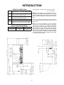
DiMENSiONS AND CAPACiTY:
Internal Dimensions of cooking compartments:
14.5” Wide x 10.75” High x 23” Front-To-Back.
(368 mm Wide x 273 mm High x 584 mm Front-
To-Back) Allow 6” 152 mm of space on the right
side if height of adjoining wall or equipment ex-
ceeds 29” 737 mm.
Capacity:
Each cooking compartment will accommodate
(9) 12” x 20” x 1” deep pans
(5) 12” x 20” x 21/2” deep pans
(3) 12” x 20” x 4” deep pans
OPTiONAL:
● 12” x 20” x 1” perforated stainless steel pans.
● 12” x 20” x 2 1/2” perforated stainless steel pans.
● 12” x 20” x 2 1/2” solid stainless steel pans.
● 12” x 20” x 4” perforated stainless steel pans.
● 12” x 20” x 4” solid stainless steel pans.
● Total Concept Descaler (case of 4 gallons).
● Casters with Strain Relief.
● P.M. Plus.
ii

SERViCE CONNECTiONS
G Gas Connection - 3/4” NPT (Male) 84,000
BTU’s.
CW1 Cold Water - Generator - 3/8” O.D. tubing,
Maximum 50 PSI, Minimum 25 PSI.
CW2 Cold Water - Condenser - 3/8” O.D. tubing,
Maximum 50 PSI, Minimum 25 PSI.
D Drain - 1/2” O.D. tube to open oor drain.
EC Electrical Connection - 120 Volts AC, 60 Hz,
single phase, comes with 6 foot cord. NEMA
5-15.
iNSTALLATiON CLEARANCE*
Left Side Right Side Rear
3 8 6
* Use on non-combustible oors only.
Gas Connection: 1/2” NPT female 3 1/2” W.C. natural
10” W.C. propane
NOTES: If the equipment is to be installed where the el-
evation exceeds 2,000 ft. (609.6 meters) above sea level,
specify installation altitudes so that the proper gas orices
can be provided. Rated Input: 42,000 BTU per compart-
ment.
All service connections are made at the bottom of the unit,
in the 6” high space between the oor and the bottom of
the cabinet.
Drain: 1 1/2” O.D. pipe coupled to 1 1/2” O.D. tempering
tank drain. Do not make solid connection to oor drain.
PVC and CPVC pipe are not acceptable materials for
drains. Before connecting water to this unit, have water
supply analyzed to make sure that hardness is no greater
than 2.0 grains per gallon and a pH level is within the
range of 7.0–8.5. Water that fails to meet these standards
should be treated by the installation of a water condition-
er. Equipment failure caused by inadequate water quality
is not covered under warranty.
iNTRODUCTiON
iii

1
iNSTALLATiON
SETTiNG iN PLACE:
The location of installation must be under an ex-
haust hood, which will remove water vapor emit-
ted when the cooker door is opened, and exhaust
combustion fumes. Level the unit in nal location by
turning the adjustable feet. Using the cabinet top as
a reference, obtain level adjustment left-to-right and
front-to-back.
MECHANiCAL CONNECTiONS:
All electrical and plumbing connections are located
on the rear panel of the unit. See ‘SERVICE CON-
NECTIONS’ on page 4 for location of mechanical
connections.
iNSTALLATiON CODES AND STANDARDS:
Installation must conform with local codes, or in ab-
sence of local codes, with the National Fuel Gas
Code - ANSI Z223.1/NFPA 54, or the Natural Gas
and Propane Installation Code, CSAB149.1 as ap-
plicable.
The appliance and its individual shut off valve
must be disconnected from the gas supply pip-
ing system during any pressure testing of that
system at pressures in excess of ½ psi.
The appliance must be isolated from the gas
supply piping system by closing its individual
manual shut off valve during any pressure test-
ing of the gas supply piping system at test pres-
sures equal to or less than ½ psi.
Electrical grounding must be provided in accor
-
dance with local codes, or in the absence of local
codes, with the National Electrical Code ANSI/NFPA
70, or the Canadian Electrical Code, CSA C22.2 as
applicable.
Ventilation must be provided in accordance with lo-
cal codes, or in the absence of local codes, with
ANSI/NFPA 96 Standard for Ventilation and Fire
Protection of Commercial Cooking Operations.
WARNiNG: Electrical grounding instructions -
Units come equipped with a three-prong
(grounding) plug for your protection against
shock hazard and should be plugged directly
into a properly grounded three-prong recepta-
cle. Do not cut or remove the grounding prong
from this plug. (120 VOLT UNITS ONLY).
1.
2.
WiRiNG DiAGRAM FOR APPLiANCE iS LO-
CATED ON RiGHT HAND SiDE PANEL OF THE
COOKER CABiNET.
EXHAUST FANS AND CANOPiES:
Canopies are set over ranges, ovens, kettles, etc.,
for ventilation purposes. It is recommended that a
canopy extend 6” past the appliance and be located
6’ 6” from the oor. Filters should be installed at an
angle of 45 degrees or more with the horizontal. This
position prevents dripping of grease and facilitates
collecting the run-off grease in a drip pan, usually
installed with the lter. A strong exhaust fan tends to
create a vacuum in the room and may interfere with
burner performance or may extinguish pilot ames.
Makeup air openings approximately equal to the
fan area will relieve such vacuum. In case of unsat-
isfactory performance on any appliance, check with
the exhaust fan in the “OFF” position.
WALL EXHAUST FAN:
Exhaust fans should be installed at least two feet
above the vent opening at the top of the unit.
CLEARANCES:
Adequate clearance must be provided in aisle and
at the side and back. Adequate clearances for air
openings into the combustion chamber must be
provided, as well as for serviceability. Use appli-
ance on noncombustible surface only. Minimum
clearance from combustible and noncombustible
construction, 3” on left side, 8” on right side and 6”
from back.
WARNiNG: THESE PROCEDURES MUST BE
FOLLOWED BY QUALiFiED PERSONNEL OR
WARRANTY WiLL BE VOiDED. AN OPEN GAP
FLOOR DRAiN iS REQUiRED iMMEDiATELY BE-
LOW THE APPLiANCE DRAiN.
TO iNSTALL:
Un-crate carefully. Report any freight damage
to the freight company immediately.
Set the unit in place. Be certain to maintain the
minimum clearances from combustibles and
non-combustibles.
Level the appliance using a spirit level.
1.
2.
3.

2
Be certain to leave adequate clearances for
cleaning, maintenance and service.
GAS CONNECTiON:
The Serial and Rating Plate on the unit indicates
the type of gas your unit is equipped to burn.
DO NOT connect to any other gas type.
A ¾” NPT line is provided at rear for the con-
nection. Each compartment is equipped with an
internal pressure regulator which is set at 3.5”
W.C. manifold pressure for natural gas and 10”
W.C. for propane gas. Use c” pipe tap on the
burner manifold for checking pressure.
An adequate gas supply is imperative. Undersized
or low pressure lines will restrict the volume of gas
required for satisfactory performance. A steady
supply pressure, between 6” W.C. and 14” W.C.
for natural gas and 11” W.C. and 14” W.C. for pro-
pane gas is recommended. With all units operating
simultaneously, the manifold pressure on all units
should not show any appreciable drop. Fluctua-
tions of more that 25% on natural gas and 10% on
propane gas will create problems, affecting burner
operation. Contact your gas company for correct
supply line sizes.
Purge the supply line to clean out any dust, dirt or
other foreign matter before connecting the line to
the unit. Use pipe joint compound which is suitable
for use with LP on all threaded connections.
Test pipe connections thoroughly for gas leaks.
WARNiNG: NEVER USE AN OPEN FLAME TO
CHECK FOR GAS LEAKS. CHECK ALL CON
-
NECTiONS FOR LEAKS USiNG SOAPY WATER
BEFORE USE.
ELECTRiCAL CONNECTiON:
120 VAC-60 Hz - Single Phase. Units with this elec-
trical rating are factory supplied with a three-wire
cord and three-prong plug which ts any standard
120V, three-prong grounded receptacle. A separate
15 amp supply is needed for each unit.
4.
1.
2.
PLUMBiNG CONNECTiONS:
NOTiCE: EQUiPMENT NOT iNSTALLED iN AC
-
CORDANCE TO THESE GUiDE LiNES MAY VOiD
THE WARRANTY.
WARNiNG: PLUMBiNG CONNECTiONS MUST
COMPLY WiTH APPLiCABLE SANiTARY, SAFE-
TY AND PLUMBiNG CODES.
CAUTiON: AN OBSTRUCTED DRAiN CAN
CAUSE PERSONAL iNJURY OR PROPERTY
DAMAGE.
Two water lines are provided. Connect water sup-
ply lines to the 3/8” copper tubes at the rear of the
steamer.
One line is for supply of water to the generator and
one for cold condensate water to condense live
steam entering the drain line.
DRAiN CONNECTiONS:
WARNiNG: AN OPEN GAP FLOOR DRAiN iS
REQUiRED iMMEDiATELY BELOW THE APPLi-
ANCE DRAiN.
CAUTiON: PVC OR CPVC ARE NOT ACCEPT-
ABLE MATERiALS FOR DRAiNS.
iNSTALLATiON

3
iNSTALLATiON
WATER CONDiTiONiNG:
It is important that the water supplied to the gen-
erator be softened to no more than 2.0 grains of
hardness and have a pH of 7.0 to 8.5. This degree
of hardness can be easily obtained with the use of
a properly maintained water softener. The use of a
water meter will determine the water consumption
and when the water softener needs regeneration or
recharging. Failure to comply with these water con-
dition standards may void the warranty.
Untreated water contains scale producing miner-
als which can precipitate onto the surfaces in the
steam generator. Due to the temperatures in the
steam generator, the minerals can bake onto the
surfaces and components. This can result in early
component failure and reduced product life. Water
level probes become coated with scale. Scale may
bridge across the probe insulator from the metal ex-
tension which senses the water level in the steam
generator shell. Once this scale becomes wet, the
water level control is unable to maintain the proper
water level in the steam generator. STRAINERS
and FILTERS will NOT remove all minerals from
the water.
OPERATiON
WARNiNG: iN THE EVENT OF MAiN BURNER iG-
NiTiON FAiLURE, A 5 MiNUTE PURGE PERiOD
MUST BE OBSERVED PRiOR TO RE-ESTAB-
LiSHiNG iGNiTiON SOURCE. iF SO EQUiPPED,
SOME UNiTS WiLL AUTOMATiCALLY RE-AT-
TEMPT iGNiTiON.
WARNiNG: iN THE EVENT A GAS ODOR iS DE-
TECTED, SHUT DOWN EQUiPMENT AT THE
MAiN SHUT OFF VALVE AND CONTACT THE
LOCAL GAS COMPANY OR GAS SUPPLiER
FOR SERViCE.
LiGHTiNG:
Ensure power, gas and water supply is on.
Turn power switch “ON”.
Generator tank will begin lling with water.
Once water level has been reached, the ignition
light will come on and remain on throughout the
operation of the appliance.
When the READY light comes on the steamer
is ready for use.
SHUTDOWN STAND-BY:
Set timer to “OFF” position and leave door slightly
open.
COMPLETE SHUTDOWN:
Set timer to “OFF” and turn power switch “OFF”.
Generator will drain automatically.
1.
2.
3.
4.
5.
1.
Turn water supply “OFF”.
Turn gas supply “OFF”
Disconnect power supply.
PREHEATiNG:
Before each initial operation of the cooker, and at
any other time when the cooking compartment is
cold, a 5-minute preheating period is required. To
preheat the cooker, put steam source into operation
and proceed as follows:
Close cooking compartment door.
Set 60-Minute Timer Dial to “5-minute” setting.
Turn off buzzer, which sounds to indicate cook-
ing is complete, by setting the Timer Dial to OFF
position.
COOKiNG:
CAUTiON: LiVE STEAM AND ACCUMULATED
HOT WATER iN THE COMPARTMENT MAY BE
RELEASED WHEN THE DOOR iS OPENED.
Before loading the cooker, be sure compartment is
hot. See preheating instructions.
Slide pans of food into cooking compartment
pan supports.
Close cooking compartment door.
2.
3.
4.
1.
2.
3.
1.
2.

4
3. Set timer cooking time:
a. HOLD - for holding cooked foods in a warm
state. Will maintain the cooking cavity at or
above 150°F (65°C).
b. 60-MINUTE TIMER - for timed cooking.
Set timer to the required cooking time (see
Cooking Guidelines).
Turn off buzzer, which sounds to indicate cook-
ing is complete, by setting timer dial to the OFF
position.
Open door slightly at rst letting most of the
steam out of the compartment and then fully
open the door.
Unload by sliding pans of food from pan sup-
ports.
CAUTiON: AN OBSTRUCTED DRAiN CAN
CAUSE PERSONAL iNJURY OR PROPERTY
DAMAGE.
Frequently check that the compartment drain and
plumbing is free of all obstructions. Never place
food containers, food or food portion bags in the
cooking compartment in such a way that the com-
partment drain becomes obstructed.
Each compartment is equipped with a removable
drain screen. Frequently check the drain screen for
accumulation of food particles. Should food parti-
cles accumulate against, or clog the drain screen,
remove it, clean it thoroughly and then replace it in
its original position.
SHUT-DOWN PROCEDURE:
No shut-down procedure is required for the cooker
except to check that both timer dials are in the OFF
position and that both compartment doors are open.
When all cooking has been completed for the day,
the steam source must be shut off.
COMPLETE SHUTDOWN:
Set timer to “OFF” and turn power switch “OFF”.
Steam generators will drain automatically.
Turn water supply “OFF”.
Close manual gas shut off valve.
3.
4.
5.
6.
7.
1.
2.
3.
Disconnect power supply.
CAUTiON: WHEN THE UNiT iS NOT iN USE,
LEAVE THE COOKiNG COMPARTMENT DOORS
UNLATCHED TO PROLONG THE LiFE OF THE
DOOR GASKET.
CLEANiNG:
After each period of daily operation (more fre-
quently as required to maintain cleanliness), the
cooker should be thoroughly cleaned by com-
pleting the following steps:
Remove left and right side pan supports by lift-
ing up and off mounting studs. Remove the drain
screen in the rear of the compartment. Wash
with a mild detergent. Rinse and set aside for
reassembly.
Wash cooking compartment interior using a mild
detergent and water. Rinse and dry thoroughly.
Replace pan supports and drain screen in com
-
partment and leave door open.
COOKiNG COMPARTMENT DRAiNAGE:
The bottom of the cooking compartment is angled
slightly toward the rear of the unit. This assures that
any condensate build-up or spills will be directed
toward the drain, which is located at the rear bot-
tom center of the cooking compartment. Any liquid
exiting the cooking compartment runs down the
cooking compartment drain tube and into the con-
densate tank.
DRiP/SPiLL TROUGH DRAiNAGE:
The Pressureless Steam Cooker has a drip/spill
trough below the cooking compartment door. It will
catch any condensate gathering on the front of the
unit when the door is opened.
WARNiNG: THE STEAMER AND iTS PARTS ARE
HOT. USE CARE WHEN OPERATiNG, CLEANiNG
OR SERViCiNG THE STEAMER. THE COOKiNG
COMPARTMENT CONTAiNS LiVE STEAM. STAY
CLEAR WHEN OPENiNG DOOR.
CAUTiON: AN OBSTRUCTED DRAiN CAN
CAUSE PERSONAL iNJURY OR PROPERTY
DAMAGE.
4.
1.
2.
3.
4.
OPERATiON

5
OPERATiON
CONTROLS:
1. Ignition Light:
When lit, indicates that pilot burner has been
ignited.
2. Ready Pilot Light:
When lit, indicates steam generator has
reached 200º Fahrenheit (93ºC) and is ready
for the cooking cycle.
3. Cooking Pilot light:
When lit, indicates that a cooking cycle is in
progress.
4. Timed Cooking/Hold Mode:
Set the cooking time (0-60 minutes) - steam
cooking will begin after the door is closed. The
cooking cycle will be interrupted if the door
is opened during the cooking cycle; resume
cooking by closing the door. Hold - For keep-
ing cooked foods warm after cooking, at or
above 150°F (65°C).
5. Main Power Switch:
On:• The steam generator will automatically ll and
begin heating to the pre-set temperature for
standby. Red light will ignite on the main power
switch.
Off:• The steam generator will drain. No lights.
Delime:
• Closes the drain valve while CLR liquid is be-
ing poured into the steam generator during the
Delime procedure. Amber light will ignite on
the main power switch.
6. Buzzer: (not shown)
Signals end of cooking period.
7. Temperature Display:
Shows temperature within the cooking cavity.
CAUTiON: LiVE STEAM AND ACCUMULATED HOT
WATER iN THE COMPARTMENT MAY BE RELEASED
WHEN THE DOOR iS OPENED.
Your steamer has been factory set when “ON” to maintain
water temperature during the READY phase at approxi-
mately 200° F (93°C) just below water boiling point. If the
steamer is used at higher elevations (above 2000 feet), a
qualied technician should adjust the READY phase tem-
perature down to an appropriate temperature, below the
boiling point of water.

6
OPERATiON
TEST KiTCHEN BULLETiN: Facts On Parade
Frozen vegetables should always be cooked in
perforated 12” x 20” x 2 ½ “ (1/1 65 mm) pans 7
½ lbs. (34 kg) maximum per pan.
Frozen entrees should be underlined with a per
-
forated pan for best results. If they are defrosted
rst, the heating time will be decreased.
Fresh foods may also be cooked in this unit.
Vegetables and other foods where the stock is
not to be retained should be cooked in perfo-
rated 12” x 20” x 2 ½” (1/1 65 mm) pans for the
most nutritious results.
There is a safety microswitch on the door which
shuts off the steam each time the door is opened
if the unit is in the cooking cycle.
Total cooking time will vary depending on
the load, even though the timer setting is the
same.
All foods, except cakes and pastry, can be
cooked in a steam cooking unit.
Steam cooked meals have greater nutritional
value since they retain most of their vitamins
and minerals.
Because foods are cooked faster by the higher
temperatures of steam cooking, they can be
prepared closer to serving time, insuring maxi-
mum freshness.
Steam cooked foods have a higher percent
yield more portions per dollar spent.
Food may be served from the same pan in which
it is steam cooked, thus reducing food breakage
since there is no extra handling or transferring
of food from cooking pans to serving pans. It
also reduces pot washing tasks.
Some important advantages of steam cook-
ing are labor saving, reduced operating costs,
space saving, and the lifting of heavy stock pots
is eliminated.
Rice and spaghetti products, if thoroughly wet
at the start of the cooking process, are very
easily prepared.
Food such as potatoes, poultry, seafood, and
some meats may be blanched in the steam
cooker, thus reducing the total cooking time and
grease absorption.
The steam cooker will loosen foods burned on
pans making washing easier.
1.
2.
3.
4.
5.
6.
7.
8.
9.
10.
11.
12.
13.
14.
Solid pans are recommended when liquid is to
be retained and perforated pans when the liquid
is not to be retained.
Eggs may be cooked out of the shell if they are
to be chopped which eliminates peeling after
steaming.
The steam cooker can be opened during the
cooking period to add or remove items.
Steam cooking information, including recom-
mended pan size and type, weight per pan,
cooking times and pan yields are given on the
following pages of this bulletin.
STEAM COOKiNG:
Your steamer efciently cooks vegetables or other
foods for immediate serving. Steam cooking should
be carefully time controlled. Keep hot food holding
time to a minimum to produce the most appetizing
results. Prepare small batches, cook only enough
to start serving, then cook additional amounts to
meet demand. Separate frozen foods into smaller
pieces to allow more efcient cooking.
Use a pan cover for pre-cooked frozen dishes that
cannot be cooked in the covered containers in
which they are packed if they require more than
15 minutes of cooking time. When cover is used,
approximately one-third additional cooking time is
necessary. Cooking time for frozen foods depends
on amount of defrosting required. If time permits,
allow frozen foods to partially thaw overnight in a
refrigerator. This will reduce their cooking time.
PREPARATiON:
Prepare vegetables, fruits, meats, seafood and
poultry normally by cleaning, separating, cutting,
removing stems, etc. Cook root vegetables in a per-
forated pan unless juices are being saved. Liquids
can be collected in a solid 12” x 20” pan placed un-
der a perforated pan. Perforated pans are used for
frankfurters, wieners and similar items when juices
do not need to be preserved. Solid pans are good
for cooking puddings, rice and hot breakfast cere-
als. Vegetables and fruits are cooked in solid pans
in their own juices. Meats and poultry are cooked in
solid pans to preserve their own juices or to retain
broth. Canned foods can be heated in their opened
cans (cans placed in 12” x 20” solid pans) or the
contents may be poured into solid pans.
15.
16.
17.
18.

7
MAiNTENANCE
PREVENTiVE MAiNTENANCE:
A good preventive maintenance program begins
with the daily cleaning procedure. Additional pre-
ventive maintenance operations are presented in
this section. In establishments that employ full-time
maintenance personnel, the tasks described can be
assigned to them. For other installations, tasks re-
quiring mechanical or electrical experience should
be performed by an authorized service agency.
The following paragraphs set for minimum preven-
tive maintenance procedures that must be com-
pleted periodically to assure continued trouble-free
operation of the cooker.
CAUTiON: Under no circumstances should
hardware (or parts) be replaced with a different
length, size, or type other than as specied in
the parts list. The hardware used in the cooker
has been selected or designed specically for
its application, and the use of other hardware
may damage the equipment and will void any
warranty.
WARNiNG: DiSCONNECT THE POWER SUPPLY
TO THE APPLiANCE BEFORE CLEANiNG OR
SERViCiNG.
WARNiNG: THE STEAMER AND iTS PARTS ARE
HOT. USE CARE WHEN OPERATiNG, CLEANiNG
OR SERViCiNG THE STEAMER. THE COOKiNG
COMPARTMENT CONTAiNS LiVE STEAM. STAY
CLEAR WHEN OPENiNG DOOR.
CLEANiNG:
At the end of each day, or between cooking cy-
cles if necessary:
Turn main power switch OFF.
Remove pans and racks from compartment and
wash in sink.
Wash compartment interior with clean water.
NOTiCE: Contact the factory, the factory
representative or a local service company
to perform maintenance and repairs should
the appliance malfunction. Refer to warranty
terms.
Use warm soapy water with a cloth or sponge
to clean exposed bead of door gasket, rinse
with warm clear water and wipe with a dry cloth.
1.
2.
3.
4.
Wipe surfaces which touch door gasket with a
cloth or sponge and warm soapy water, rinse
with warm clear water and wipe with a dry cloth.
Do not apply food oils or petroleum solvents or
lubricants directly to door gasket or surfaces
which touch door gasket.
Remove drain screen from inside compartment
drain. Using a plastic bottle brush and mild de-
tergent, clean inside the drain opening ensuring
there is no food residue or blockage. Clean the
drain screen and replace in its original position.
Leave door slightly open when steamer is not
in use.
CAUTiON: DO NOT USE CLEANiNG AGENTS
THAT ARE CORROSiVE.
Weekly, or more often if necessary:
Clean exterior with a damp cloth and polish with
a soft dry cloth.
Use a non-abrasive cleaner to remove discol-
orations.
Clean around burner air mixer and orice if lint
has accumulated. Side cover must be removed
to clean this area.
Monthly:
Clean around burner air mixers, louvered pan-
els if grease or lint has accumulated.
Following daily and periodic maintenance proce-
dures will enhance long-life for your equipment. Cli-
matic conditions - salt air - may require more thor-
ough and frequent cleaning otherwise the life of the
equipment could be adversely affected. It is NOT
RECOMMENDED to use cleaning agents that are
corrosive.
Use of cleaning agents that contain chloride, acids
or salts which are corrosive may cause pitting and
corrosion when used over a period of time; this will
reduce the life of the appliance.
Should pitting or corrosion occur, this is not covered
by warranty. Follow the recommended cleaning in-
structions. Use a mild detergent, warm water and
rinse thoroughly.
5.
6.
1.
2.
3.
1.

8
MAiNTENANCE
NEVER SPRAY WATER iNTO ELECTRiC CON-
TROLS OR LOUVERS. MONTHLY REMOVAL OF
SCALE DEPOSiTS
It is recommended that your steamer be delimed
once a month, or more often if necessary.
Should your steamer develop a heavy build-up of
lime scale deposits, use the CLR TREATMENT KIT
available from your authorized service agent.
Before beginning deliming procedures, ensure that
water is not overowing into the cooking compart-
ment.
DELiMiNG PROCEDURE:
Both generators must be delimed individually.
WARNiNG: READ AND FOLLOW iNSTRUC-
TiONS ON THE CLR BOTTLE. USE PLASTiC OR
RUBBER GLOVES TO AVOiD SKiN CONTACT.
iF CLR COMES iN CONTACT WiTH SKiN, RiNSE
WiTH CLEAN WATER.
Completely drain steam generator by setting
on/off switch to “OFF”. Set cooking timer to 0.
Set on/off switch to DELIME.
Unscrew the deliming cap at the top side of
steamer. The left port is for the lower genera-
tor and the right port is for the upper generator.
Slowly pour 20 ounces of solution into genera-
tor to avoid spillage. Replace the deliming cap
so it seals tightly. Turn power switch to on.
Operate steamer in READY cycle for ½ hour,
then turn on/off switch “OFF” and allow genera-
tor to drain.
Flush cycle: Turn on/off switch to “ON”. When
ready light comes on, switch to “OFF” to ush
generator. Repeat this step three times to com-
pletely ush generator.
Clean exterior and interior. Use a mild solution
of soap and water. Rinse with clean water.
Dry with a soft cloth. LEAVE COMPARTMENT
DOOR OPEN WHEN NOT IN USE.
The steamer is now ready for use. Turn off for
overnight shutdown.
1.
2.
3.
4.
5.
6.
7.
8.
DOOR GASKET REPLACEMENT:
The cooking compartment door gaskets are made
of a silicone-type rubber material that is very du-
rable but subject to wear during normal operation.
Should the gasket leak replace it.
Open the cooking compartment door.
Remove the four screws on the outside of the
door frame, and remove the door panel assem-
bly.
Remove the six screws from the gasket plate in
the door panel assembly.
Remove the gasket plate and the door gasket
from door panel.
Install the new door gasket to the door panel.
Replace the gasket plate and six screws.
Reassemble the door panel assembly in the
door frame using the four screws.
Gasket replacement is now complete.
Door may be difcult to close until gasket has com-
pressed to conform to opening. Leaving door closed
overnight will compress gasket.
EXTERiOR PANEL REMOVAL:
WARNiNG:
To prevent hazard in servicing the
cooker, be certain that the steam supply boil-
er is shut down, the cold water shut-off valve
is closed, and the electrical disconnect circuit
breaker for the Cooker/Boiler unit is OFF before
removing side panels.
Access to all internal plumbing and electrical as-
semblies is from the right side. The right-side panel
is removed by removing the bottom screws from
panel. Gas controls are located in the lower cabinet
and are accessible from the front of the unit.
STAiNLESS STEEL:
To remove normal dirt, grease or product residue
from stainless steel, use ordinary soap and water
(with or without detergent) applied with a sponge or
cloth. Dry thoroughly with a clean cloth. Never use
vinegar or any corrosive cleaner.
To remove grease and food splatters or condensed
vapors that have baked on the equipment, apply
cleanser to a damp cloth or sponge and rub cleans
-
er on the metal in the direction of the polishing lines
1.
2.
3.
4.
5.
6.
7.

9
MAiNTENANCE
on the metal. Rubbing cleanser as gently as pos-
sible in the direction of the polished lines will not
mar the nish of the stainless steel. NEVER RUB
WITH A CIRCULAR MOTION.
Soil and burnt deposits which do not respond to the
above procedure can usually be removed by rub-
bing the surface with SCOTCH-BRITE scouring
pads or STAINLESS scouring pads. DO NOT USE
ORDINARY STEEL WOOL as any particles left on
the surface will rust and further spoil the appear-
ance of the nish. NEVER USE A WIRE BRUSH,
STEEL SCOURING PADS (EXCEPT STAINLESS),
SCRAPER, FILE OR OTHER STEEL TOOLS. Sur-
faces which are marred collect dirt more rapidly
and become more difcult to clean. Marring also in-
creases the possibility of corrosive attack. Renish-
ing may then be required.
TO REMOVE HEAT TiNT:
Darkened areas sometimes appear on the stainless
steel surface where the area has been subjected to
excessive heat. These darkened areas are caused
by thickening of the protective surface of the stain-
less steel and are not harmful. Heat tint can nor-
mally be removed by the foregoing, but tint which
does not respond to this procedure calls for a vig-
orous scouring in the direction of the polish lines
using SCOTCH-BRITE scouring pads or a STAIN-
LESS scouring pad in combination with a powdered
cleanser. Heat tint action may be lessened by not
applying or by reducing heat to equipment during
slack periods.
REMOVAL OF SCALE DEPOSiTS:
See Deliming Procedure, Page 8.
TROUBLE-SHOOTiNG
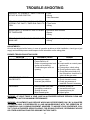
GENERAL TROUBLE-SHOOTiNG GUiDE:
PROBLEM PROBABLE CAUSE REMEDY
COOKING INDICATOR LIGHT FAILS
TO LIGHT WITH TIMER SET.
a. Main power circuit breaker
tripped.
b. Door interlock switch contacts
not closed.
c. Door interlock switch faulty.
d. Indicator light burned out.
e. Faulty timer contacts.
f. Faulty wiring.
a. Locate external circuit breaker
for in coming power and place
in ON position.
b. Shut cooker door to close
switch contacts. Check
alignment of door with switch.
c. Replace switch.
d. Replace light.
e. Replace timer.
f. Inspect condition of wire and
tightness of all connections.
Correct as needed.
STEAM FAILS TO ENTER COOK-
ING COMPARTMENT WITH COOK-
ING INDICATOR LIGHT ON.
a. Faulty wiring. a. Inspect condition of wire and
tightness of all connections.
Correct as needed.
STEAM ENTERS COMPARTMENT
CONTINUOUSLY WITHOUT THE
COOKING OR READY LIGHT ON.
a. Standby thermostat not set
correctly.
b. Faulty thermostatic switch.
c. HOLD set on timer.
a. Adjust the thermostat lower.
b. Replace thermostat.
c. Rotate timer knob to ‘OFF’
position.
TIMER DIAL NOT TURNING.
a. Faulty timer motor.
b. Faulty wiring.
a. Replace timer.
b. Inspect condition of wire and
tightness of all connections.
Correct as needed.

10
BUZZER FAILS TO SOUND AT END
OF TIMER SETTING.
a. Timer contacts faulty.
b. Buzzer faulty.
c. Faulty wiring.
a. Replace timer.
b. Replace buzzer.
c. Inspect condition of wire and
tightness of all connections.
Correct as needed.
STEAM FLOWS CONTINUOUSLY
FROM DRAIN LINE WITH COOKER
IN OPERATION.
a. Cold water not connected.
b. Faulty cooling valve.
c. Faulty wiring.
a. Turn on external shutoff valve.
b. Replace cooling valve.
c. Inspect condition of wire and
tightness of all connections.
Correct as needed.
*DOOR LEAKS. a. Damaged door gasket.
b. Clogged compartment drain or
plumbing.
a. Check gasket for cuts and
replace.
b. Remove screen and clean
drain line or plumbing.
*WATER FLOWS INTO COOK-
ING COMPARTMENT.
a. Level control has failed.
b. Water has very high
resistance.
c. Scale build-up on probe.
d. Water ll solenoid valve.
a. Replace.
b. Replace level control with high
sensitivity control.
c. Clean all probes
d. Plugged, defective, clean or
replace.
*WATER ACCUMULATES IN
COMPARTMENT.
a. Plugged compartment drain. a. Remove screen and clean
drain line.
*WATER FLOWS INTO DRAIN
DURING SHUTDOWN.
a. Cooling valve does not close. a. Check valve for foreign
material or damage.
*WATER NOT BEING SUP-
PLIED TO GENERATOR.
a. Water supply off.
b. Supply water pressure too low.
c. Defective water solenoid
valve.
d. Level Probe shorted.
e. Defective water level control.
f. Drain valve is open.
a. Check incoming water valve
is on.
b. Call supply agency.
c. Replace or clean.
d. Check and correct.
e. Replace.
f. Check valve, clean or replace.
*NOTE: THESE PROBLEMS ARE AN iNDiCATiON OF SEVERE WATER CONDiTiONS WHiCH SHOULD BE CORRECTED
iMMEDiATELY TO AVOiD DAMAGE TO THE COMPONENTS AND PERFORMANCE OF THE STEAMER. CALL YOUR SER-
ViCE AGENCY FOR ASSiSTANCE.
ELECTRiCAL FAULT iSOLATiON GUiDE:
FAiLURE FAULT LOCATiON
WILL NOT OPERATE IN EITHER HOLD OR 60-
MINUTE TIMER POSITIONS.
a. Incoming power
b. Timer
c. Door interlock switch
d. Wiring
OPERATING IN HOLD POSITION BUT NOT IN
60-MINUTE TIMER POSITION
a. 60-Minute timer
b. Wiring
TROUBLE-SHOOTiNG

11
TROUBLE-SHOOTiNG
OPERATES IN 60-MINUTE TIMER POSITION
BUT NOT IN HOLD POSITION
a. Timer
b. Wiring
c. Hold thermostat.
WITH COOK INDICATOR LIGHT ON AND STEAM
ENTERING THE CAVITY, TIMER DIAL FAILS TO
TURN.
a. Hold position set on timer.
b. Timer motor
c. Wiring
BUZZER FAILS TO SOUND AT END OF 60-MIN-
UTE TIMER MODE.
a. 60-Minute timer contacts
b. Buzzer
c. Wiring
STEAM FLOWS CONTINUOUSLY FROM BOILER
DRAIN LINE.
a. Cooling valve needs replacing
b. Wiring
ADJUSTMENTS:
All units are adjusted at the factory. In case of operation problems at initial installation, check type of gas
supply and manifold pressure and compare it with information on the rating plate.
BURNER TROUBLE-SHOOTiNG GUiDE:
PROBLEM PROBABLE CAUSE REMEDY
BURNERS DO NOT COME ON. a. Gas supply is off.
b. Power switch is off.
c. Probe not sensing water level.
d. Ignitor not functioning.
e. Combination gas valve not
opening.
a. Locate supply line and turn
on.
b. Locate switch on control panel
and turn on.
c. Clean probes, check wiring.
d. Check ignition module, relay.
e. Check that control knob is in
the ON position, check that 24
volts is at the gas valve.
BURNERS PRODUCE CAR-
BON DEPOSITS
a. Incorrect orice size.
b. Incorrect gas supply.
c. Incorrect gas pressure.
a. Check size and correct.
b. Check size and correct.
c. Check gas pressure at
manifold. Correct if necessary.
FLASH BACK a. Burning inside mixer tube.
b. Incomplete combustion.
c. Sooting of burner.
d. Miss-located ignitor.
a. Reduce primary air.
b. Increase burner input.
c. Increase primary air.
d. Adjust ignitor.
WARNiNG: AT LEAST TWiCE A YEAR, HAVE AN AUTHORizED SERViCE PERSON CLEAN AND
ADJUST THE UNiT FOR MAXiMUM PERFORMANCE.
WARNiNG: ADJUSTMENTS AND SERViCE WORK MAY BE PERFORMED ONLY BY A QUALiFiED
TECHNiCiAN WHO iS EXPERiENCED iN, AND KNOWLEDGEABLE WiTH THE OPERATiON OF
COMMERCiAL GAS COOKiNG EQUiPMENT. HOWEVER, TO ASSURE YOUR CONFiDENCE, CON-
TACT YOUR AUTHORizED SERViCE AGENCY FOR RELiABLE SERViCE, DEPENDABLE ADViCE
OR OTHER ASSiSTANCE AND FOR GENUiNE FACTORY PARTS.

12
60-MiNUTE TiMER / TiMER CONTACTS:
Defective timer contacts will result in failure of
cooker compartment to operate. When this occurs,
remove the side panel and proceed as follows:
Turn off power to the cooker at external circuit
breaker.
Disconnect all ve wires from timer terminals.
Connect an ohmmeter between terminals 1 &
3.
Rotate timer dial beyond the “0-Minute” point
(any setting) to obtain a reading of zero ohms
on the ohmmeter. If zero ohm reading cannot
be obtained, timer contacts are defective and
the timer must be replaced.
Move ohmmeter leads to terminals 1 and 4.
Rotate timer dial to “0 - Minute” position (an
audible click indicates correct position). If zero
ohm reading cannot be obtained, the timer is
defective and must be replaced.
Remove ohmmeter and replace all ve leads on
timer terminals.
TiMER MOTOR:
A defective timer motor will cause continuous op-
eration in the TIME mode, with the timer dial failing
to return to the “0 - Minute” position.
To conrm timer motor condition, proceed as fol-
lows:
Carefully check motor wire leads and tighten
loose connections.
WARNiNG: Use care while working with con-
trol panel. Terminals carry 120 Volts.
Turn on power to the steamer.
Set timer dial (any setting beyond “0 - Minute”).
If operation is correct, the motor will turn the dial
toward “0 - Minute”. If the motor fails to oper-
ate, it is defective and the entire timer must be
replaced.
Shut off power to the cooker.
DOOR iNTERLOCK SWiTCH:
Malfunction of the cooker door interlock switch
prevents timer indicator lights from turning on and
steam generator from operating when the timer dial
is set. If steam does not enter the compartment and
1.
2.
3.
4.
5.
6.
7.
1.
2.
3.
4.
the cooking indicator light fails to turn on with the
door latch securely engaged, the fault may be in the
door interlock switch. Proceed as follows:
Turn off power to the cooker.
Disconnect wires to the door switch terminals.
Connect an ohmmeter between the terminals of
the switch.
Actuate the switch by closing the cooking com-
partment door. If a zero reading cannot be ob-
tained, the switch is defective and must be re-
placed.
Remove the ohmmeter and replace the leads
on switch terminals.
iNDiCATOR LiGHTS:
If the cooker compartment functions correctly, with
the single exception that the indicator light fails to
light during operation, the fault is a defective indica-
tor light. A “burned out” or defective light is veried
by using an AC volt-meter at the leads, with input
power on the selector switch in the correct position
for that timer, the timer set, and the door latches
closed. If 120 volts is present, the fault is in the in-
dicator light and requires replacement. If 120 volts
is not present, the fault is in the wiring or control
components (selector switch, timer or door switch).
BUzzER:
If the buzzer does not sound at the termination of
the operator-selected timer setting (timer dial re-
turned to “0 - Minute” position), the fault may be a
defective buzzer. Buzzer operation is veried using
an AC volt-meter at buzzer coil connections with
input power on and selector switch and coinciding
timer dial set at the “0 - Minute” position. If voltage
is 120 volts, the fault is in the buzzer, which must
be replaced. If 120 volts is not present, the fault is
in the wiring or control components (timer or selec-
tor switch).
WiRiNG:
Using an ohmmeter, wiring continuity between the
connections shown on the wiring diagram is read-
ily veried. This is best done in stages, removing
only those wires required for each continuity check.
As each lead is replaced, it should be checked for
evidence of corrosion, and cleaned if necessary. All
leads must be tightly attached so as to provide a
good electrical connection.
1.
2.
3.
4.
5.
TROUBLE-SHOOTiNG

13
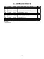
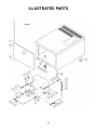
iLLUSTRATED PARTS
Main Assembly

14
iLLUSTRATED PARTS
iTEM PART NO. REF. NO. DESCRiPTiON QTY.
1 97-6334 5224-2 Compartment Strainer 2
2 97-6177 8-5023 Perforated Trough 1
3 97-6175 2681-3 Pan Rack 4
4 97-6269 3977-2 Hinge Rod 1
5 97-6191 9-3213 Door Switch 2
97-6429 39332 Switch Actuator 2
6 97-6178 8-5021 Striker 2
7 97-6430 7712-1 Control Panel Decal 1
8 97-6170 4-PL04 Ready Pilot Light, Green, 125V 2
9 97-5472 4-PL04-2 Ignition Pilot Light, Green, 28V 2
10 97-6171 4-PL07 Pilot Light, Red, 125V 2
11 08-3826 Knob 2
12 97-6367 9124-2 Switch, On/Off/Delime 2
13 08-7521 Temperature Indicator 2
91-6491 Grommet 2
14 97-6227 8-5060-8 Outer Door Shell 2
15 97-6432 3903-2 Door Handle Assembly 2
16 97-6232 8-5068-9 Latch Assembly 2
17 97-6236 9-3366 Spacer 3
18 97-6261 8-5078 Bushing 8
19 97-6230 8-5065-8 Door Panel 2
20 97-6228 8-5063-8 Door Gasket 2
21 97-6229 8-5064-8 Gasket Retaining Plate 2
22 97-6233 9-1011-1 Gasket Panel Screws 12
23 97-6481 9017-2 Hose Clamp, 5/8” 4
**24 97-6434 9219-300 Hose, 5/8 I.D. x 30” Long, Upper Generator Drain 1
97-6435 9219-120 Hose, 5/8 I.D. x 12” Long, Lower Generator Drain 1
25 97-6436 3-6910E Brass Elbow, 5/8”C x 3/4” MPT 2
26 97-6210 3-S543 Blowdown Solenoid Valve 2
27 97-6209 3-6810E Connector, 5/8” C x 3/4” MPT 2
28 97-6437 6440-1 Right Side Panel 1
**29 97-6438 9219-340 Hose, 5/8” I.D. x 3/4” Long, Upper Cavity Drain 1
97-6439 9219-160 Hose, 5/8” I.D. x 16” Long, Lower Cavity Drain 1
30 97-6440 3-646 Brass Tee, 3/8”C 1
31 97-6188 3-696A Brass Elbow, 3/8”C x 1/8” MPT 3
32 97-6344 3-686A Brass Connector, 3/8” C x 1/8” MPT 4
33 97-6441 39294 Timer Relay, Cooling 1
34 97-6186 9092-2 Fuse, 2A, 250V 2
35 97-5864 9068-1 Fuse Holder 2
36 10-6962 4-22ES End Section 1

15
iLLUSTRATED PARTS
37 10-6963 4-22TB Terminal Block 2
38 97-5441 4-35EU Ground Lug 1
39 97-6282 5162-1 Solenoid Valve 3
40 97-6193 9-3174-1 Relay DPDT, 120V 4
41 97-6327 3-716A Brass Tee, 3/8”C x 1/8” MPT x 3’8”C 1
42 97-6442 39148 Bulk Head Union, 3/8”C 2
43 97-6443 9017-5 Hose Clamp, 1-1/16 - 2” 4
44 97-6444 9230-016 Drain Hose, 1-1/4” x 1-3/4” Long 2
45 97-6445 7714-1 Drain Tube Assembly 2
46 97-5702 4127-3 Cord Set, 120V 1
47 97-6418 7349-2 Generator Tank, Lower 1
48 97-6419 39355 High Limit Thermostat
49 97-6194 4038-4 Liquid Level Control, 10K OHM 2
50 97-5701 9-3383 Transformer, 120-24V 2
51 97-6187 9126-1 Operating Thermostat 2
52 97-5572 9210-1 Ignition Module 2
53 97-6172 9-3175-1 Relay SPDT, 120V 2
54 97-6190 3821-1 Buzzer 2
55 97-6420 3-116CB Brass Street Elbow, 3/8” FPT x 1/4” MPT 4
56 97-6421 9053-7 Brass Hose Barb, 5/8” x 3/8” MPT 4
57 97-6422 9017-3 Hose Clamp, 5/8 - 1-1/4” 12
58 97-6423 9219-112 Steam Diverter Hose, 5/8 I.D. x O.D. x 11-1/4”Long 4
59 08-6464 Timer, 60 Minutes, 120V 2
**60 97-6424 9219-210 Upper Delime Hose, 5/8” I.D. x 21” Long 1
97-6425 9219-370 Lower Delime Hose, 5/8” I.D. x 37” Long 1
61 97-6426 9053-6 Brass Hose Barb, 5/8” x 3/4” MPT 2
62 97-6203 3-101E Brass Tee, 3/4” 2
63 97-6204 3-112E Brass Close Nipple, 3/4” 2
64 97-6202 3-100E Brass Elbow, 3/4” 2
65 97-6368 5184-1 Relief Valve Extension 2
66 97-6427 4517-2 Top Panel 1
67 97-6428 3-113E5-1/2 Brass Nipple, 3/4” x 5 1/2” 2
68 97-6219 5286-1 Relief Valve, 5 PSI 2
69 91-7594 Reducing Elbow Assembly 2
91-7765 Clean Port Plug 2
08-7511 O Ring 2
70 97-6372 3738-7 Probe - High Level 2
71 97-6213 3738-8 Probe - Low Level 2
72 97-6212 3738-9 Probe - Low Level Cut Off 2
73 08-6502 Pressure Switch 2
74 97-6202 7349-1 Generator Tank, Top 1

16
75 97-6446 9222-080 Tubing, Pressure Switch, 1/4” I.D. x 8” Long 2
76 97-6447 9053-8 Brass Hose Barb, 1/4” x 1/8 MPT 4
77 97-6448 5703-1 Pressure Switch Bracket 2
78 08-5015 Vacuum Breaker 2
79 97-6449 39252 Tubing, Vacuum Break, 1/4” I.D. x 2” Long 2
80 97-6450 3-X101A Brass Extruded Tee, 1/8” FPT 2
81 97-6451 3-112A Brass Close Nipple, 1/8” NPT 2
82 97-6452 3-110BA Brass Bushing, NPT, 1/4” to 1/8” 2
83 97-6453 3-110DB Brass Bushing, NPT, 1/2” to 1/4” 2
84 97-6454 3-111D Brass Locknut, 1/2” NPT 2
85 10-4586 Sealing Nut, 1/2” NPT 2
*86 97-6455 39447 Timer Relay, Operating 2
*
Not Shown.
** Select as required.
iLLUSTRATED PARTS
Page is loading ...
Page is loading ...
Page is loading ...
Page is loading ...
-
 1
1
-
 2
2
-
 3
3
-
 4
4
-
 5
5
-
 6
6
-
 7
7
-
 8
8
-
 9
9
-
 10
10
-
 11
11
-
 12
12
-
 13
13
-
 14
14
-
 15
15
-
 16
16
-
 17
17
-
 18
18
-
 19
19
-
 20
20
-
 21
21
-
 22
22
-
 23
23
-
 24
24


Market Forge ETP-10G Operating instructions
- Category
- Cookers
- Type
- Operating instructions
Ask a question and I''ll find the answer in the document
Finding information in a document is now easier with AI
Related papers
-
Market Forge ST-12-TGG Operating instructions
-
-
-
-
-
-
Market Forge EPT-10G Datasheet
-
-
-
Other documents
-
 T & S Brass & Bronze Works MV-2522-22 Datasheet
-
Market Forge Industries ETP-10G Installation, Operation & Maintenance Manual
-
Crown GSX-10HE User manual
-
Blodgett SN-3E Operating instructions
-
-
-
-
Vulcan-Hart VSX5G User manual
-
Southbend GC-3S User manual
-
Southbend GDA-2S Owner's manual
