INSTALLATION & OPERATION MANUAL 10124 REV 0 (03/21)
PAGE
5
OF20
G F S
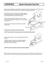
UNPACKING
IMMEDIATELY INSPECT FOR SHIPPING DAMAGE
Immediately after unpacking the steamer, check for possible shipping damage. If the steamer is found to be damaged,
save the packaging material and contact the carrier within 15 days of delivery.
located on the left side panel.
INSTALLATION INSTRUCTIONS
INSTALLATION
WARNING
ELECTRICAL GROUNDING INSTRUCTIONS
This appliance is equipped with a three-prong (grounding) plug for your protection against shock hazard
and should be plugged directly into a properly grounded three-prong receptacle. Do not cut or remove the
grounding prong from this plug. (120V units only).
WARNING
Do not connect the appliance to the electrical supply until after the gas connection has been made.
Installation must conform to local codes, or in absence of local codes, with the National Fuel Gas Code - ANSI Z223.1/
NFPA 54, or the Natural Gas and Propane Installation Code, CSA B149.1, as applicable.
pressure testing of that system at pressures in excess of 1/2 psi (3.5 kPa).
during any pressure testing of the gas supply piping system at test pressures equal to or less than ½ psi (3.5 kPa).
Electrical grounding must be provided in accordance with local codes, or in the absence of local codes, with the National
Electrical Code ANSI/NFPA 70, or the Canadian Electrical Code, CSA C22.2, as applicable.
Ventilation must be provided in accordance with local codes, or in the absence of local codes, with ANSI/NFPA 96
Standard for Ventilation and Fire Protection of Commercial Cooking Operations.
WIRING DIAGRAM FOR APPLIANCE IS LOCATED ON RIGHT HAND SIDE PANEL OF THE COOKER CABINET.
E F Canopies
Canopies are set over ranges, ovens, kettles, etc., for ventilation purposes. It is recommended that a canopy extend
vacuum. In case of unsatisfactory performance on any appliance, check with the exhaust fan in the “OFF” position.
W E F
The exhaust fan should be installed at least two feet above the vent opening at the top of the unit.