Page is loading ...

INSTALLATION AND OPERATION MANUAL
Post in a prominent location, instructions to be followed in the event the user smells gas.
This information shall be obtained by consulting the local gas supplier.
MARKET FORGE INDUSTRIES, INC.
35 GARVEY STREET EVERETT, MA 02149-4403
TEL 6173874100 TELEX 94-94 1 4
FAX: 617 387 4450 OUTSIDE MA 800 227 2659
FORM NO. S-2465 REV B 12-9-96
PRINTED IN USA

1. INTRODUCTION
1.1 To The Kitchen Manager 1.1
1.2 Description 1.1
1.3 Cooking Capacities 1.1
1.4 Basic Functioning 1.1
2. INSTALLATION.
2.1 Setting in Place 2.1
2.2 Service 2.1
2.3 Before Use 2.2
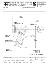
Figure 2.1 - Service Connections
locations & dimensions 2.3
Table 2.1 - Service Connections
specifications & details 2.3
2.4 Service Connections 2.3
2.4.1 Water Connections 2.4
2.4.2 Electrical Connections 2.4
2.4.3 Gas Connections 2.4
2.4.4 Initial Systems Inspection 2.4
2.3 Reversing the Doors 2.5
3. INITIAL SYSTEMS INSPECTION
3.1 General 3.1
3.2 Warm-up 3.1
3.3 Steam Demand 3.1
3.4 STEAM Mode 3.2
3.5 STEAM & HOLD Mode 3.2
3.6 CONSTANT STEAM Mode 3.2
3.7 Steam Suppression System 3.2
3.8 Shut-Down 3.3
4. OPERATION
4.1 Controls and Indicators 4.1
4.2 Operating Procedures 4.1
4.2.1 Startup and Preheating 4.1
4.2.2 Cooking 4.1
4.2.3 Shut Down 4.2
Figure 4.1 - Control Panel 4.2
Table 4.1 - Controls and Indicators 4.3
Figure 4.2 - Removal for Daily Cleaning 4.4
Table 4.2 - Removal for Daily Cleaning 4.4
4.3 Daily Cleaning 4.5
4.4 Prolonged Shut-Down & Cleaning 4.5
5. TROUBLESHOOTING
5.1 General 5.1
Troubleshooting Table 5.1 -5.5
5.2 Water Level Control Board 5.6
6. MAINTENANCE
6.1 General 6.1
6.2 Daily Cleaning 6.1
6.3 Preventative Maintenance 6.1
Figure 6.1 - Assembly of Exterior Sheet
Metal Panels to Unit 6.2
Table 6.1 - Assembly of Exterior Sheet
Metal Panels Parts List 6.2
6.4 Cleaning the Generator 6.3
6.4.1 Cleaning Instructions 6.3
6.5 Cleaning the Ventilation Ductwork 6.4
6.6 Electrical Box Service Access 6.4
Figure 6.2 - Electrical Panel 6.5
Table 6.2 - Electrical Panel Parts List 6.5
Principles of Operation Schematic 6.7
Wiring Diagram 6.8 - 6.9
6.7 Control Panel Service Access 6.10
Table 6.3 - Control Panel Parts List 6.10
Figure 6.3 - Control Panel Assembly 6.11
6.8 Door Adjustment 6.12
6.8.1 Door Alignment 6.12
6.8.2 Door Latch Tension 6.12
Figure 6.4 - Door Latch Assembly 6.13
Table 6.4 - Door Latch Parts List 6.13
6.8.3 Door Handle Tension 6.13
Figure 6.5 - Door Assembly: 6.14
Table 6.5 - Door Assembly Parts List 6.15
MARKET FORGE INDUSTRIES, INC
35 GARVEY STREET EVERETT, MA 02149
TEL 6173874100 TELEX 94-9414
FAX 6173874456 OUTSIDE MA 800 227 2659

6.9 Door Gasket Replacement 6.15
Figure 6.6 - Upper Generator Assy 6.16
Table 6.6 - Upper Gen Parts List 6.17
Figure 6.7 - Lower Generator Assy 6.18
Table 6.7 - Lower Gen Parts List 6.19
Figure 6.8 - Exhaust Duct Assy 6.20
Table 6.8 - Exhaust Duct Parts List 6.21
Figure 6.9 - Blower Box Assembly 6.21
Table 6.9 - Blower Box Parts List 6.21
6.10 Solenoid Fill Valve Screen Service 6.22
Table 6.10 - Tempering Tank Parts List 6.22
Figure 6.10 - Tempering Tank Assy 6.23
Figure 6.11 -Gas Tubing Assy 6.24
Table 6.1 I - Gas Tubing Parts List 6.5
Figure 6.12 - Chassis Assembly 6.26
Table 6.12 - Chassis Assy Parts List 6.27
Table 6.13 - Tubing Routing List 6.28
Figure 6.13 - Tubing Routing 6.29
MARKET FORGE INDUSTRIES, INC
35 GARVEY STREET EVERETT, MA 02149
TEL 6173874100 TELEX 94-9414
FAX 6173874456 OUTSIDE MA 800 227 2659

1. Introduction
1.1 TO THE KITCHEN MANAGER
1. Read this manual carefully and in its entirety. Contact
Market Forge Industries, Inc. for clarification if necessary.
2. Protect your kitchen personnel from scalding and other
serious injury by providing training programs to acquaint
all equipment operators with the correct and safe
methods of operation.
3. Operators must be made aware of the consequences
of misuse. Steam producing equipment, no matter who
the manufacturer, is inherently dangerous when misused.
The possibility of serious scalding always exists, the
careless and/or untrained operator will be injured.
4. This equipment must be maintained according to the
guidelines In this manual (see Section 6, "Maintenance").
Lack of maintenance will lead to a potentially hazardous
condition and possible liability. Operators should report
any equipment malfunction immediately and steps must
be taken to correct the problem before further use of the
equipment is allowed.
5. KEEP THIS MANUAL FOR DAILY REFERENCE.
WARNING:
IMPROPER INSTALLATION, ADJUSTMENT,
ALTERATION, SERVICE OR MAINTENANCE CAN
CAUSE PROPERTY DAMAGE, INJURY OR DEATH.
READ THE INSTALLATION. OPERATION, AND
MAINTENANCE INSTRUCTIONS THOROUGHLY
BEFORE INSTALLING OR SERVICING THIS
EQUIPMENT
1.2 DESCRIPTION
The Steam Tech Plus is a pressureless steam
cooker consisting of two independently controlled
cooking compartments in a single cabinet. Each
compartment has its own Independent control
panel, consisting of a power switch, mode select
switch, constant steam switch, timer (mechanical or
electronic), steam demand indicator, and indicator
lights for each of its functions. The Steam Tech
Plus is equipped with a steam suppression safety
system. These Features and functions will be
discussed in greater detail in Sections 3.
1.3 COOKING CAPACITIES
Each cooking compartment will accept:
• Three 12" x 20" x 2 1/2 pans, or
• Three I/I gastronorm pans, 65mm deep.
The inside dimensions of the cooking compartment
are:
Width- 14 1/2 (368mm) Height-103/4" (273mm) Depth
- 23" (584mm)
1.4 BASIC FUNCTIONING
Each Steam Tech Plus cooking compartment has its
own independent steam generator. Each of its two
cooking compartments may be operated either
Independently or simultaneously. Each compartment
is equipped with identical controls. These controls
allow it to be used in the "TIMED STEAM" mode,
"CONSTANT STEAM" untimed mode. or the "STEAM
& HOLD" mode.
MARKET FORGE INDUSTRIES, INC.
35 GARVEY STREET EVERETT, MA 02149
TEL: 017 387 4100 TELEX: 94-94 1 4
FAX: 6 1 7 387 4456 OUTSIDE MA 800 227 2659 1.1

The Steam Tech Plus utilizes a unique STEAM
DEMAND feature. This feature allows the Steam Tech
Plus to operate at extremely high cooking efficiencies.
The Steam Demand system creates only the amount of
steam as will be absorbed by the food being cooked,
no more and no less. No excess steam is created,
therefore, nothing is lost down the drain.
To begin operation, the POWER switch is
pressed into the ON position, illuminating the power
light. This opens the water feed solenoid valves, to
both the steam generator and tempering tank. Once
the appropriate water level has been reached, the
burner is ignited. When the water temperature in the
steam generator has reached 193°F, the green READY
light, is illuminated, indicating that the unit is now ready
to make steam and all controls are functional.
A steaming mode is selected with the MODE
SELECT switch. After selecting a steaming mode, the
TIMER knob must be set to the desired cooking time to
activate the main burner and begin making steam.
In the STEAM mode, the unit will create steam
for the duration of time you have set. Once the timer
reaches the end of its cycle (0 minutes), the unit will
stop making steam, and the buzzer will sound. The
buzzer is silenced by returning the timer knob to the
OFF position. The generator will continue to idle at
193°F.
In the STEAM & HOLD mode, the unit will create
steam for the duration of time you have set. Once the
timer reaches the end of its cycle (0 minutes), the unit
will stop making steam and go into the HOLD mode,
illuminating the amber hold light. When in the HOLD
mode, the auxiliary thermostatically controlled electric
strip heater is activated. The strip heater is mounted
onto the outside of the cooking compartment and will
maintain a safe internal holding temperature. The unit
will now act as a holding cabinet until you call for steam
again. During this time, the generator will continue to
idle at 193°F.
The CONSTANT STEAM button overrides the
MODE SELECT switch and the TIMER. When the
button is depressed, the green constant steam light is
illuminated. In this mode, the generator will constantly
supply steam, as controlled by the Steam Demand
System, regardless of the MODE SELECT switch and
TIMER setting, until the CONSTANT STEAM button is
pressed again. While the CONSTANT STEAM button is
depressed, the TIMER may be used as an alarm only,
as it will have no effect on the creation of steam. To
exit the constant steam mode, the CONSTANT STEAM
button must be pressed again. This will cause the
green constant steam light to go off. The generator will
now idle at 193°F, ready to make steam.
All drainage is routed through the common
tempering tank, which regulates the drain water
temperature. This tank cools the drain water to 130°F
before discharging it down the main drain line.
NOTE: Read this manual carefully and in its
entirety. Contact Market Forge Industries, Inc. for
clarification if necessary
Product Service Department
Market Forge Industries, Inc.
35 Garvey Street
Everett, Massachusetts 02149
Telephone: (617) 387-4100
The model and serial numbers must be
referenced when corresponding with Market Forge.
The data plate containing the serial number is located
on the top of the unit.
NOTE: It is the owner/manager's respon-
sibility to provide instruction to kitchen equipment
operators. The instruction must include the safe
operation of all equipment. Operators must report
malfunctioning equipment immediately so the
equipment can be taken out of service and
repaired.
MARKET FORGE INDUSTRIES, INC.
35 GARVEY STREET EVERETT, MA 02149 1.2
TEL: 017 387 4100 TELEX: 94-9414
PAX: 6 17 387 4456 OUTSIDE MA 800 227 2659
1. Introduction

2.1 SETTING IN PLACE
The assembled Steam Tech Plus Pressureless
Steam Cooker is shipped bolted to a skid, with the
cabinet feet shipped in a separate container. Steps
required for assembly are as follows:
I - Remove the four bolts which secure the unit to the
skid.
2- Install the feet into the threaded mounting
locations on the bottom of the unit.
3- Mount the left and right pan support racks on the
mounting brackets located inside each of the
cooking compartments.
NOTE: The racks with the metal baffling mount on
the right (steam inlet) side of the cooking
compartments.
4- A location must be selected under an exhaust
hood which will remove the products of gas
combustion, along with the small amounts of vapor
emitted from the cooker during normal operation.
5- Level the unit after it is placed in its final location.
This is accomplished by turning the bottom part of
the adjustable feet. Using the cabinet top as a
reference, obtain level adjustment left-to-right and
front-to-back.
6- Remove all instructional materials from the
cooking compartments and leave both doors
slightly ajar.
2.2 SERVICE
Required service, both preventative and
corrective, is explained in Section 6 of this manual.
Should repairs be required, a network of authorized
agencies is available to assist with prompt service. A
current Directory of Authorized Service Agencies may
be obtained by contacting:
Product Service Department
Market Forge Industries, Inc. 35
Garvey Street
Everett, Massachusetts 02149
Telephone: (617) 387-4100
The model and serial numbers must be
referenced when corresponding with Market Forge.
The data plate containing the serial number is located
on the top of the unit.
An electrical diagram is located on pages 6.8 -6.9
of this manual, along with a schematic of the principles
of operation on page 6.7. For more in depth technical
information on the Steam Tech Plus, consult your
Market Forge Factory Authorized Service Agency
Representative. An electrical diagram is also posted on
the inside of the front cover panel of the unit, for your
convenience.
These diagrams show only a single compart-
ment system, but are representative of both
systems, as the top and bottom cooking compart-
ment systems are the same. The top system circuits
on the unit have an "A" designation following the wire
numbers, while the bottom system circuits have a "B"
designation following the wire numbers.
NOTE: It is the owner/manager's responsi-
bility to provide instruction to kitchen equipment
operators. The instruction must include the safe
operation of all equipment. Operators must report
malfunctioning equipment immediately so the
equipment can be taken out of service and
repaired.
MARKET FORGE INDUSTRIES, INC. 2.1
35 GARVEY STREET EVERETT, MA 02149
TEL: 61 7 387 4100 TELEX: 94-94 1 4
FAX: 6 1 7 387 4456 OUTSIDE MA 800 227 2659
2. Installation

2.3 BEFORE USE
Before proceeding to Section 2.4, Service
Connections, be sure you have road and under-
stand the following statements.
•Keep this appliance free and dear from
combustibles.
• Do not obstruct the flow of combustion and
ventilation air.
•This installation, must conform with local codes,
or in the absence of local codes, with the
National Fuel Gas code, ANSI Z223.1, the
Natural Gas Installation Code. For installation
in Canada, this appliance is to be in accor-
dance with the current Natural Gas Installation
Code CAN/CGA-B149.1, or the Propane Gas
Installation Code. CAN/CGA-B149.2 . and/ or
Local Codes as applicable, including:
•The generator and its individual shut off
valve must be disconnected from the gas
supply piping system during any pressure
testing of that system at test pressure in
excess of 1/2 psig (3.45 k/PA).
•The generator must be isolated from the gas
supply system by closing its individual
manual shut off valve during any pressure
testing of the gas supply piping system at
test pressures equal to or less than 1/2 psig
(3.45k/PA).
•This appliance, when installed, must be
electrically grounded in accordance with local
codes, or in the absence of local codes, with
the National Electric code, ANSI/NFPA70-
Latest Edition. For installation in Canada, all
electrical connections are to be made in
accordance with CSA C22. 1 Canadian
Electrical Code Part I and/or Local Codes.
•This product must be installed in a room with
adequate air supply.
•Do not place any objects on or directly against
the unit that will block air openings into the
combustion chamber.
•Minimum clearances from both combustible and
non combustible surfaces are 2" (51 mm) from
right side wall, 2" (51 mm) from left wall and 6"
(152mm) from rear wall. Suitable for installation
on combustible floors.
•This unit is serviceable almost entirely from the
front. Do not install in such a manner that a
service person cannot access the lower front
cover panel. Some of the componentry may be
more easily accessed by removing either of the
side panels and/or the back panel, as shown in
Figure 6.1, on page 6.2 of this manual. The
minimum suggested clearance for servicing this
unit from the left or right sides is 18". The
minimum suggested clearance for servicing this
unit from the rear is 12"
The steps for side panel removal are as
follows:
1. To remove either side panel, remove the
screw from the center of the bottom edge of
the panel.
2. Slide the side panel upwards until it stops.
3. Swing the bottom edge of the side panel out
away from the unit far enough (about 1.5
inches), so that it is free to slide down to the
floor.
4. This will allow the top edge of the side panel
to slide out from under the top cap of the unit.
To remove the back panel, remove the 8 screws
which attach it to the unit, as shown in Figure
6.1, on page 6.2 of this manual.
•There are no special lighting or shut down
procedures for the burners. Each burner is
controlled by the POWER, switch for that
generator.
• Keep this manual for daily reference.
MARKET FORGE INDUSTRIES, INC.
35 GARVEY STREET EVERETT, MA 02149 2.2
TEL: 617 387 4100 TELEX: 94-94 I 4
FAX: 617 387 4456 OUTSIDE MA 800 227 2659
2. Installation

Table 2.1 Service
Connections
specifications and details
G
Gas Supply Connection-
1/2" NPT
EC
Electrical Connection -
120 VAC, 60hz, 1/2" conduit or equivalent.
Current draw for 120V control circuitry is 6.5
Amps. Use wire suitable for at least 90°C.
CW
Cold Water -
1/2" NPT to cold water supply manifold. Cold
water supply line to have a maximum of 50 PSI
(3.5 kg/cm2) and a minimum of 25 PSI (1.8
kg/cm2) water pressure.
D
Drain -
1 1/2" 0. D. pipe coupled to 1 1/2" 0. D.
tempering tank drain. DO NOT MAKE SOLID
CONNECTION TO FLOOR DRAIN.
F
Flue-
Place unit so that the Flue is under an exhaust
hood to remove the products of gas combus-
tion. DO NOT TOUCH FLUE! The Flue
reaches extremely high temperatures!
1.4 SERVICE CONNECTIONS
All service connections are made at the bottom of
the unit, in the 6 inch high space between the floor and
the bottom of the cabinet. Please see Figure 2.1 and
Table 2.1 for service connections, details and
dimensions.
NOTE:
If the equipment is to be installed where the
elevation exceeds 2,000 feet (609.6 meters) above
sea level, specify installation altitudes so that the
proper gas orifices can be provided.
MARKET FORGE INDUSTRIES, INC.
35 GARVEY STREET EVERETT, MA 02149
TEL: 617 387 4100 TELEX: 94-9414 2.3
PAX: 6 I 7 387 4456 OUTSIDE MA 800 227 2659
2. Installation

2.4.1 Water Connections
Before connecting water to this unit, have water
supply analyzed to make sure that hardness is no
greater than 2.0 grains per gallon and pH level is within
the range of 7.0 - 8.5. Water which fails to meet these
standards should be treated by the installation of a
water conditioner. EQUIPMENT FAILURE CAUSED
BY INADEQUATE WATER QUALITY IS NOT
COVERED UNDER WARRANTY.
CAUTION: PVC OR CPVC PIPING ARE NOT
ACCEPTABLE MATERIALS FOR USE IN DRAINS.
2.4.2 Electrical Connections
Connect cooker controls to 110/120 volt AC, 60
Hz, single phase branch circuit rated 15 amps capacity.
Wiring will conform to the requirements of national and
local electrical codes, (220 volts, 50Hz, single phase
for export units.
NOTE: ONLY A LICENSED ELECTRICIAN SHOULD
MAKE ELECTRICAL CONNECTIONS.
2.4.3 Gas Connections
Each of the generators are factory adjusted for a
gas input of 40,000 BTU/hr at the pressure indicated.
Please read the rating plate on the top of the unit. If
this plate is marked for a different gas than that
supplied, notify your dealer immediately. Install the
supplied external gas supply shut off valve at the gas
main inlet. This is located just under the bottom edge of
the lower front cover panel. Install so that the shut off
valve handle is clearly visible to the operator.
Use new iron or steel pipe complying with the
latest ANSI Standard for Wrought-Steel and Wrought-
lron Pipe, B36, Properly threaded, reamed and free
from chips, oil, and dirt. If pipe dope is used, apply a
moderate amount leaving two end threads bare. Pipe
dope must be resistant to LP gas. Connect the gas line
into the bottom (inlet) side of the gas
supply shut off valve. The supply pressure must be at
least I" (25mm) water column higher than the manifold
or regulator pressure for proper functioning of the
regulator. If it is not, check the supply pipe for blockage
or excessive pressure drop and make the necessary
corrections.
Perform a gas leak test of all newly-made joints,
as well as those leading to the main gas control valve.
Use a soap solution. DO NOT USE FLAME!
Natural gas units are equipped with a pressure
regulator factory adjusted to give 3.5" (89mm) water
column manifold pressure.
Propane gas units are equipped with a pressure
regulator factory adjusted to give 11" (279.5mm) water
column manifold pressure.
For conversion to either natural or propane
gas, 3 components must be changed. They are:
1. Gas orifices for each of the main burners.
2. Both complete pilot burners.
3. Springs inside each of the gas regulator
valves.
Consult the Market Forge for more detailed
information, instructions, and part numbers for
field conversion to either natural or propane gas.
NOTE: ONLY A LICENSED GAS FITTER SHOULD
MAKE GAS LINE CONNECTIONS.
2.4.4 Initial Systems Inspection
After the cooker is set in place, and all service
connections have been made, the cooker must be
given a final systems inspection prior to use. This is to
determine that all systems are functioning properly.
This procedure is described in full detail in Section 3,
"Initial Systems Inspection", of this manual. If all
systems perform as described in Section 3, the cooker
is ready for cooking use. If any of the systems are not
functioning as they should, consult Section 5,
"Troubleshooting" in this manual.
MARKET FORGE INDUSTRIES, INC.
35 GARVEY STREET EVERETT. MA 02149 2.4
TEL: 61 7 387 4100 TELEX: 94-94 1 4
2. Installation

2.5 REVERSING THE DOORS
The Steam Tech Plus Pressureless Steam
Cooker has cooking compartment doors which are
reversible, for your convenience. For Door Assembly
illustration and table, refer to pages 6.14 and 6.15.
NOTE: This procedure is identical for both the
upper and lower cooking compartment doors.
1. Remove the left large side panel by removing the
screw from the center of the bottom edge of the
panel. Gripping one of the louvers, slide the
panel upwards until the bottom edge of the panel
is free to swing out slightly away from the unit.
Slide the panel down until its top edge is dear of
the top cap of the unit.
2. Open Cooking Compartment door.
3. Remove the two 5/16" bolts that attach the top
hinge to the front of the unit.
4. Slide the door upwards, off the bottom hinge.
5. Remove the two 5/16" bolts that attach the bottom
hinge to the front of the unit.
NOTE: The top hinge is slightly larger than
the bottom hinge.
6. Remove the 4 black plastic hole plugs from the
front of the unit. Push the black hole plugs into
the now vacant left upper and lower hinge
mounting holes.
7. Reinstall the top (larger) hinge and bolts into the
right lower hinge mounting holes. Rotate the
hinge 180° for installation, so that the pin
which the door rides on is now facing up. The
hinge must be rotated because it will now
function as the bottom hinge. DO NOT
COMPLETELY TIGHTEN THE HINGE
MOUNTING BOLTS YET These will be used
later for adjusting the door.
8. Remove the door latch assembly from the
face of the unit. The 2 door latch mounting nuts
are located behind the face of the unit and must
be accessed by removing the large side panels.
9. Remove the two white hole plugs from the left
door latch mounting holes, and insert them into
the right door latch mounting holes (where the
door latch assembly was originally mounted).
10. Rotate the door latch assembly 180°, and
install into the left door latch mounting holes.
NOTE: Each stud on the latch assembly should
have a plastic washer, a spring, a plastic washer
and a Nyloc type nut, as shown In Figure 6.5 on
page 6.14.
11. To adjust the tension of the door latch, tighten
both nuts down until the springs are fully
compressed, then back each nut off 1/2 turn.
12. Replace large side panel by placing the panel
against the side of the unit. Be sure that the top
edge of the side panel slides under the top cap
of the unit. Slide the panel upwards until it stops.
Then, while pushing the panel in towards the
unit, slide it down into position. Replace screw.
13. Rotate the door 180° for mounting.
14. Slide the remaining (small) hinge into the top
door bearing.
15. Slide the door and hinge assembly down onto
the hinge which you have already mounted to
the front of the unit. Use the two 5/16" bolts to
mount the top hinge into the right upper hinge
mounting holes. DO NOT COMPLETELY
TIGHTEN THE HINGE MOUNTING BOLTS
YET. These are used later for door adjustment.
16. Door Adjustment is covered in Section 6.8 on
page 6.12 of this manual.
MARKET FORGE INDUSTRIES, INC.
35 GARVEY STREET EVERETT, MA 02149 2.5
TEL: 617 387 4100 TELEX: 94-94 1 4
FAX: 0 1 7 387 4456 OUTSIDE MA 800 227 2659
2. Installation

3.1 GENERAL
This section contains information for you to test
and familiarize yourself with the operation of the Steam
Tech Plus.
After the unit is completely assembled, all
packaging materials removed, and all service
connections are made, all systems must be given a
thorough check-out before being put into operation. Be
sure that the cooking compartments are empty, and all
pan support racks are in place. Confirm that all service
connections are on. Select a cooking compartment to
test. Close the cooking compartment door, and turn the
timer knob to the OFF position.
Figure 3.1, below, illustrates the position of the
controls and Indicators for operation.
NOTE: REPEAT STEPS IN SECTIONS 3.2
THROUGH 3.7 FOR BOTH THE UPPER AND
LOWER COOKING COMPARTMENTS TO INSURE
PROPER FUNCTIONING OF THE ENTIRE UNIT.
3.2 WARM-UP
Push the POWER switch Into the ON position.
The power light will come on immediately, along with
the fan motor. You will hear water entering the unit
through the solenoid valves, filling both the steam
generator and tempering tank.
Once the water levels in the steam generator
and tempering tank have reached the appropriate
level, the solenoid valves will close, and the burner
will Ignite. After a short time (approximately 5
minutes), the green READY light will come on,
indicating that the unit is ready to make steam.
3.3 STEAM DEMAND
Due to the unique nature of this design, it is
important to understand what the STEAM DEMAND
system does. The STEAM DEMAND system is the
means by which the Steam Tech Plus monitors and
creates steam. This system uses very sensitive sensors
to monitor the minute steam fluctuations inside the
cooking compartment. These fluctuations are an
indicator of how much steam energy the food inside the
cooking compartment is using. The sensor controls the
burner, Insuring that steam is created only as fast as it
will be accepted by the food inside the cooking
compartment, no more and no less.
This system can be monitored by observing the
red STEAM DEMAND indicator, located at the top of the
control panel. The STEAM DEMAND indicator will light
up red only when steam is called for, and will cycle on
and off throughout the cooking cycle.
Figure 3.1 Control Panel
• Note that your unit may come equipped with an independent POWER. ON
Indicator, located to the left of the Power Switch.
MARKET FORGE INDUSTRIES, INC.
35 GARVEY STREET EVERETT, MA 02149 3.1
TEL: 017 387 4100 TELEX: 94-94 1 4
FAX: 617 387 4456 OUTSIDE MA 800 227 2659
3. Initial Systems Inspection

3.4 STEAM MODE
Turn the MODE SELECT switch to the STEAM
mode. Set the TIMER, knob to 10 minutes. Immedi-
ately, the STEAM ON window, located near the top of
the control panel, should light up green. At the same
time, the STEAM DEMAND window should light up red.
After a short time, the red STEAM DEMAND light will
begin to cycle on and off, while the green STEAM ON
light stays on continuously.
When the timer reaches 0 minutes, the buzzer
will sound, and both the STEAM ON and the STEAM
DEMAND lights will turn off. The buzzer is silenced by
returning the TIMER knob to the OFF position. The
green READY light will stay illuminated.
3.5 STEAM & HOLD MODE
Turn MODE SELECT switch to the STEAM &
HOLD mode. Set the TIMER knob to 10 minutes.
Immediately, the STEAM ON window, located near the
top of the control panel, should light up green. At the
same time, the STEAM DEMAND window should light
up red. After a short time, the red STEAM DEMAND
light will begin to cycle on and off, while the green
STEAM ON light stays on continuously.
When the timer reaches 0 minutes, the HOLD
window will light up amber. Both the STEAM ON and
the STEAM DEMAND lights will turn off. The green
READY light will stay Illuminated.
While the HOLD light is on, the cooking
compartment will function as a holding cabinet,
maintaining a safe food holding temperature of
approximately 160°F, indefinitely (as long as power is
supplied to the unit). Each of the cooking compart-
ments has its own independent temperature gauge.
The cooking compartment temperature gauges are
mounted on the right hand side of the steam vent
hoods, directly above the control panel for each of the
cooking compartments.
3.6 CONSTANT STEAM MODE
The CONSTANT STEAM button overrides all
other cooking modes. When the CONSTANT STEAM
button is depressed, the CONSTANT STEAM window,
located next to the CONSTANT STEAM button, will
light up green. Immediately, the STEAM ON window,
located near the top of the control panel, should light up
green. At the same time, the STEAM DEMAND window
should light up red. After a short time, the red STEAM
DEMAND light will begin to cycle on and off, while the
green STEAM ON light remains illuminated
continuously.
NOTE: Even in the Constant Steam mode, the
generator will only create as much steam as will be
accepted by the food inside the cooking compartment.
No matter what mode has been selected, the red
STEAM DEMAND indicator will cycle on and off.
The generator will continuously make steam as
needed, until the CONSTANT STEAM button is
released (by pressing it again) and the green CON-
STANT STEAM light goes off.
CAUTION: The timer is useful only as an alarm when in
the CONSTANT STEAM mode. The timer will count
down, but it will have no effect on the continuous
generation of steam, as it will be overridden by the
CONSTANT STEAM button.
3.7 STEAM SUPPRESSION
The proper operation of the Steam Suppression
system is evidenced by the lack of steam billowing out
of the cooking cavity when the door Is opened. While
the generator is creating steam, open the door to the
cooking compartment. As soon as the door is opened,
a solenoid valve will open, sending water to a spray
nozzle inside the steam generator. You should hear the
spray for approximately 3 to 4 seconds. At the same
time, both the STEAM ON and the STEAM DEMAND
lights will turn off. The green READY light will stay
illuminated.
MARKET FORCE INDUSTRIES, INC.
35 GARVEY STREET EVERETT, MA 02149 3.2
TEL: 617 387 4100 TELEX: 94-94 1 4
FAX: 6 17 387 4456 OUTSIDE MA 8OO 227 2659
3. Initial Systems Inspection

Also, when the door is opened, any residual steam
will be drawn up into the steam vent hood. The steam
vent hoods are located above each cooking
compartment
When the door is closed, the STEAM ON and the
STEAM DEMAND windows will light up again. At the
same time, a bubbling sound may be heard, as the cool
air is evacuated from the cooking compartment and
replaced with fresh steam from the generator. The unit
will continue to cycle normally, as it was before the door
was opened.
NOTE: REPEAT STEPS IN SECTIONS 3.2
THROUGH SECTION 3.7 FOR BOTH THE UPPER AND
LOWER COOKING COMPARTMENTS TO INSURE
PROPER FUNCTIONING OF THE ENTIRE UNIT
BEFORE PROCEEDING TO THE NEXT PARAGRAPH,
(3 8 SHUTDOWN).
3.8 SHUTDOWN
No special procedure is necessary for shutting the
unit down. Simply press the POWER switch into the OFF
position. All indicator lights on the control panel will go out,
and the generator for that cooking compartment will drain.
The tempering tank will not drain until both POWER
switches are in the OFF position
CAUTION: When the unit is not in use, leave both
cooking compartment doors slightly ajar to extend the
life of the cooking compartment door gaskets.
Please note that the TIMER should be in the OFF
position and the CONSTANT STEAM button should be
disengaged upon restarting the unit to avoid any
unintentional generation of steam on startup.
NOTE: As a final test of the unit before use in
cooking food, both generators should be shut down,
allowing both the generators and tempering tank to
completely drain.
MARKET FORGE INDUSTRIES INC
35 QARVEYSTREET EVERETT. MA 02149
TEL 0173874100 TELEX 949414
FAX 6 1 7 387 4456 OUTSIDE MA 800 227 2659
3. Initial Systems Inspection

4.1 CONTROLS AND INDICATORS
The controls and indicators used to operate the Steam
Tech Plus pressureless steam cooker are listed and described
in Table 4.1, on page 4.3. Their locations are called out in
Figure 4.1, on page 4.2.
4.2 OPERATING PROCEDURES
This section includes general instructions for daily
operation of the Steam Tech Plus pressureless steam
cooker. You should review Section 3.1 through
Section 3.8 of this manual if you are unfamiliar with the
functions of the Steam Tech Plus. If you require more
detailed technical information on the Steam Tech Plus'
various systems and their functions, please consult
your Market Forge Factory Authorized Service Agency
Representative.
4.2.1 Start-up and Preheating
The Steam Tech Plus pressureless steam cooker
requires no start-up procedure. Simply press the
POWER switch into the ON position. The ignitor will
attempt to ignite the burner for up to 90 seconds, If
after 90 seconds, the burner hasn't ignited, the gas
ignition control will go into lockout. The system will
then need to be manually reset by pressing the
POWER switch into the OFF position for 5 minutes.
Wait 5 minutes before turning the unit on again.
The tempering tank and selected cooking
compartment's steam generator will fill with water.
Once full, the burner will automatically preheat the
water in the generator to 193°F. This will take
approximately 7 minutes. When the generator is ready
to create steam, the green READY light will come on.
4.2.2 Cooking
NOTE: The green READY light must be on
before any controls become operational.
1. Slide pans of food into the cooking compartment
pan support racks.
2. Firmly close the cooking compartment door.
3. Select a cooking cycle, either timed or untimed.
4. For timed cooking, set the MODE SELECT switch
to the desired cooking mode and set the TIMER,
to the desired cook time.
5. At the end of a timed cook cycle (when the timer
has timed out to zero), return the TIMER knob to
the OFF position to:
a. Silence the buzzer (when using the
STEAM Mode).
b. Exit the HOLD function (when using the
STEAM & HOLD Mode).
6. For untimed cooking, press the CONSTANT
STEAM button to override the TIMER and create
continuous untimed steam.
7. When using the untimed cooking cycle, and you
have determined that the food in the cooking
compartment is done, press the CONSTANT
STEAM button again to exit the CONSTANT
STEAM Mode.
8. In any cooking cycle or mode, the Steam
DEMAND light will cycle on and off. This indicates
the automatic creation of steam as it is called for
by the food being cooked.
CONDENSATE WARNING:
Normal steam cooking conditions will create
some condensate due to temperature differences
between the steam and the objects/surfaces it
contacts. When an excessive volume of
condensate appears in the cooking compartment,
the steam generator water level control should be
checked for possible malfunction and the need for
maintenance. Continued use of the equipment,
without maintenance, will create a potential for
scalding.
MARKET FORGE INDUSTRIES, INC,
35 GARVEY STREET EVERETT, MA 02149 4.1
TEL-6173874100 TELEX: 94-94 1 4
FAX: 617 387 4456 OUTSIDE MA 800 227 2659
4. Operation

4. Operation
Figure 4.1
Control Panel
4.2.3 Shut-down
No Shut Down procedure is required for the
Steam Tech Plus. Simply press the POWER Switch
into the OFF position. When shut down, all indicator
lights on the control panel for that cooking compart-
ment will go out, and the generator for that com-
partment will automatically drain. The tempering tank
will not drain until both POWER switches ore in the
OFF position.
When a cooking compartment Is not in use, be
sure to leave its door slightly ajar to extend the life of
the cooking compartment door gasket. When the unit is
completely shut down, both cooking compartment
doors should be left ajar.
NOTE: To avoid the unintentional creation of
steam upon startup, return both timer knobs to the OFF
position and be sure that both CONSTANT STEAM
switches are disengaged.
MARKET FORGE INDUSTRIES, INC.
35 GARVEY STREET EVERETT, MA 02149
TEL: 617 387 4100 TELEX: 94-9414 4.2
FAX: 6 I 7 387 4456 OUTSIDE MA 800 227 2659

4. Operation
Power Switch
Located at the bottom of the control panel. Pressing this switch into the ON position will
supply power to unit and activate the corresponding system. Pressing this switch into the
OFF position will cut off power to the corresponding system and shut down the unit.
Power Indicator
Located in the body of the POWER SWITCH. Lights up red when the POWER SWITCH Is
pressed into the ON position.
Ready Light
Located above the POWER SWITCH. Lights up green when the corresponding generator
has warmed up, indicating that it is ready to create steam.
Mode Selector Switch
Located in the center of the control panel, just above the ready light. Turn the switch to the
right to select the STEAM mode. Turn the switch to the left to select the STEAM & HOLD
mode.
Timer Knob
Located near the top of the control panel. Turn the timer knob clockwise to set the cook
time.
Steam On Indicator
Located near the top of the control panel. Lights up green when any cooking mode is
active.
Steam Demand Indicator
Located above the Steam On indicator. Lights up red as the product you are cooking calls
for steam. It will cycle on and off at varying rates depending on the quantity and product
being cooked.
Hold Indicator
Located near the center of the control panel, on the left side. Lights up amber when the
unit is in the HOLD mode.
Temperature Gauge
Located on the right side of each of the steam hoods, above the control panel. They are
used to monitor the internal temperature of the cooking compartments during the HOLD
mode.
Constant Steam Switch
Located near the center of the control panel, on the right side. Press the button once to
engage it and enter the CONSTANT STEAM mode. Press it again to disengage it and exit
the CONSTANT STEAM mode.
Constant Steam Indicator
Located next to the Constant Steam button. Lights up green whenever the unit Is in the
CONSTANT STEAM mode.
Clean Generator Warning
Indicator
Located in the lower right side of the control panel. This will light up red when the
generator needs to be de-limed.
Table 4.1
Controls and Indicators
MARKET FORGE INDUSTRIES, INC.
35 GARVEY STREET EVERETT, MA 02149 4.3
TEL: 6 17 387 4100 TELEX: 94-94 I 4
FAX: 6 I 7 387 4456 OUTSIDE MA 800 227 2659

4. Operation
Table 4.2 - Daily Cleaning Parts List, (single cooking compartment shown*)
ITEM QTY.* DESCRIPTION PART NO.
1 1 A-la-carte Tray E91-5782
2 1 Cooking Compartment Drain Screen E91-5718
3 1 Drip / Spill Trough Screen E91-5769
4
1
Left Pan Slide
E91
-
5700
5 1 Right Pan Slide E91-5698
*NOTE The components and quantities shown on this page are for a single cooking compartment only. These
components and quantities are identical for both the upper and lower cooking compartments.
MARKET FORGE INDUSTRIES, INC.
35 GARVEY STREET EVERETT, MA 02149 4.4
TEL: 617 387 4100 TELEX: 94-94 I 4
FAX. 6 1 7 387 4456 OUTSIDE MA 800 227 2659

4.3 DAILY CLEANING
After each period of daily operation (more frequently as
required to maintain cleanliness) the cooker should be
thoroughly cleaned by completing the following steps:
1. Remove the left and right side pan support racks by
lifting them up off their mounting brackets.
2. Remove the a-la-carte tray from the floor of the
cooking compartment by lifting the front of the tray
off the mounting pins and sliding it forward.
3. Remove the drain screen from the rear wall of the
cooking cavity by sliding it up off its mounting tabs.
4. Wash cooking compartment interior using detergent
and water. Rinse and dry thoroughly.
5. Remove upper and lower Drip/Spill Trough screens.
Lift the left side of the screen up and swing it out
away from the face of the unit until it Is free to slide
out from under the control panel housing.
6. Wash all removed pieces with a detergent, using a
brush, and rinse. These pieces can also be sent
through a commercial automatic dishwashing
machine. Set these pieces aside for reassembly.
7. Replace the Drip/Spill Trough screens by sliding the
right hand side of the screens under the control
panel housing. Then swing the left hand side of the
screen in towards the face of the unit until the
screen is free to drop down into position.
8. Replace drain screen onto rear wall of cooking
compartment by sliding it down onto its mounting
tabs.
9. Replace a-la-carte tray by sliding it back until it drops
down onto its mounting pins.
10. Replace pan supports into cooking cavity by
hanging them on their mounting brackets. 8e sure
to hang the support with the metal baffling on it on
the right (steam inlet opening) side of the cooking
cavity.
4.4 PROLONGED SHUT-DOWN AND CLEANING
1. Press the both POWER switches into the OFF position. The
steam generators and tempering tank will automatically
drain.
2. Clean the cooking compartment, as described in Section
4.3 of this manual.
3. The Steam Generator must be Rinsed & Drained. Refer to
Section 6.4, Cleaning the Generator, for complete
instructions.
4. Turn gas valve to the OFF position.
CAUTION:
• Disconnect the power supply to the steam generators
before servicing.
• Keep appliance area free & clear from combustibles.
• Don't obstruct the flow of combustion & ventilation air.
• Contact the factory, the factory representative, or a factory
authorized service company to preform maintenence and
repairs.
• In the event of a power failure, no attempt should be made
to operate this appliance. Be sure both power switches are
in the OFF position.
• Keep this manual for daily reference.
MARKET FORGE INDUSTRIES, INC.
35 GARVEY STREET EVERETT, MA 02149 4.5
TEL: 617 387 4100 TELEX: 94-9414
FAX: 017 387 4456 OUTSIDE MA 800 227 2659
4. Operation

5.1 GENERAL
The information in this section is intended to assist the
operator, maintenance and the service personnel in locating
the source of problems which may occur with the cooker.
Before following any of the procedures given in this section,
the operator/maintenance person should be thoroughly
familiar with the "Operation" Section of this manual.
If the problem cannot be readily corrected without the
use of tools, the operator/maintenance person should contact
the nearest Market Forge service agency for assistance.
TROUBLE POSSIBLE CAUSE REMEDY
POWER Light does not come on
when the POWER Switch is
pressed into the ON position.
1. No 120v power to unit.
2. Fuse blown.
3. Faulty POWER Switch.
1. Be sure 120v power supply is on.
2. Replace fuse.
3. Check/replace POWER Switch.
Water enters the steam generator
and/or tempering tank very slowly.
1. Dirty strainer screen in the water fill solenoid
valve.
2. Dirt or lime accumulation on seat of water fill
solenoid valve.
1. Clean/replace strainer screen.
2. Clean valve seat.
Steam generator will not fill.
1. Faulty generator fill solenoid valve. 2. Faulty
generator drain solenoid valve.
1. If 120 Volt is verified at the solenoid
coil, but the valve fails to open, replace
solenoid.
2. If 120 Volt is verified at the solenoid
coil, but the valve fails to close, replace
solenoid.
Tempering tank will not fill. 1. Fuse blown.
2. Faulty tempering tank fill/cool solenoid valve.
3. Faulty tempering tank drain solenoid valve.
1. Replace fuse.
2. If 120 Volt is verified at the solenoid
coil, but the valve fails to open, replace
solenoid.
3. If 120 Volt is verified at the solenoid
coil, but the valve fails to close, replace
solenoid.
MARKET FORCE INDUSTRIES, INC.
35 GARVEY STREET EVERETT, MA 02149 5.1
TEL: 617 387 4100 TELEX: 94-94 1 4
FAX: 6 17 387 4456 OUTSIDE MA 800 227 2659
5. Troubleshooting

5. Troubleshooting
TROUBLE POSSIBLE CAUSE REMEDY
Warm-Up Burner will not ignite. 1. No gas supply to unit. 1. Make sure that gas service is
connected and turned on.
2. No gas supply to gas regulator valve. 2.
Make sure that the manual safety gas
valve is turned on.
3. No gas supply beyond gas regulator valve. 3. Make sure that the main regu
lator gas
valve is turned on.
4. Faulty Warm-up burner solenoid valve in gas
regulator.
4. If 24 volts is verified at the solenoid
coil, but valve fails to open, replace gas
regulator.
5. Faulty ignition/flame sensor control module. 5. See Ignition/Flame Sensor Control
Diagnostic section.
6. Faulty ignitor. 6. Check electrical connections.
* Be sure ignitor gap is 1/8".
* Check ignitor alignment.
* Be sure ignitor is seated properly in
its mounting.
Warm-Up Burner will not stay lit. 1. Faulty ignition/flame sensor control module. 1. See Ignition/Flame Sensor Control
Diagnostic section.
2. Faulty ignitor/flame sensor. 2. * Check etectrical connections.
*Be sure ignitor gap is 1/8".
*Check ignitor alignment.
*
Be sure ignitor is seated properly in its
mounting.
3. Sediment trap may be full. 3. Empty sediment trap. Be sure to turn
off main gas supply!
READY light will not come on. 1. Faulty 190°F generator thermostat. 1. Check/replace 190°F generator
thermostat.
2. Faulty READY light. 2. Check/replace READY light.
MARKET FORGE INDUSTRIES, INC.
35 GARVEY STREET EVERETT, MA 02149 5.2
TEL: 6 17 387 4100 TELEX: 94-94 1 4
FAX: 617 387 4456 OUTSIDE MA 800 227 2659
/