Page is loading ...

ABB Network Partner
User´s manual and
Technical description
SPAJ 131 C
Overcurrent relay
RS 421 Ser.No.
SPAJ 131 C
2
5
1028D
f
n
= 50Hz
60Hz
1
2
3
4
5
/
>
tt
n
/
II
n
)(
>
I
n
)(
>>
I
>>
/
tt
%
[]
%
[]
U
aux
80...265V
~
–
18...80V
–
n
I
=
1A 5A
SPCJ 3C3
REGISTERS
0000
1
2
3
4
5
6
7
8
01
SGR
L1
IRF
>
I
L2
I
L3
I
I
1309
[ ]
s
k
>
t
0.5
0.05 1.0
13
2.5
0.5
0.04 1.0
0.5
1.5
2.5
STEP
RESET
SG1
0
1
1
2
3
4
5
6
7
8
20
STEP
>>
I
n
I
>
I
n
I
>>
I
>>
t
[ ]
s
>
I
>>
I
SPCJ 3C3
B

2
1MRS 750660-MUM EN
Issued 97-02-24
Version A (replaces 34 SPAJ 20 EN1)
Checked
Approved
Data subject to change without notice
Station
Automation
SPAJ 131 C
Overcurrent relay
Contents
Features .......................................................................................................................... 2
Application.....................................................................................................................3
Description of operation................................................................................................. 3
Connections ................................................................................................................... 4
Configuration of output relays ....................................................................................... 6
Start and operation indicators......................................................................................... 7
Combined power supply and I/O module ...................................................................... 7
Technical data ................................................................................................................ 8
Examples of application................................................................................................ 10
Secondary injection testing........................................................................................... 18
Maintenance and repair................................................................................................ 22
Spare parts.................................................................................................................... 22
Ordering numbers ........................................................................................................ 22
Dimensions and instructions for mounting .................................................................. 23
Order information........................................................................................................ 23
The complete manual for the three-phase overcurrent relay SPAJ 131 C includes
the following partial manuals:
Overcurrent relay SPAJ 131 C, general description 1MRS 750660-MUM EN
Three-phase overcurrent relay module SPCJ 3C3 1MRS 750602-MUM EN
General characteristics of C-type relay modules 1MRS 750328-MUM EN
Features
Three-phase low-set phase overcurrent stage
with definite time or inverse time characteristic
High-set phase overcurrent stage with definite
time characteristic
Both overcurrent stages can be blocked by an
external control signal
Output relay functions freely configurable for
desired operation
Flexible adaptation of relay to specific applica-
tions
Local numerical display of setting values, meas-
ured values and recorded fault values
Serial interface for two-way data communica-
tion over fibre-optic bus between relay and
substation and/or remote control systems
Continuous self-supervision of hardware and
software, including auto-diagnostics

3
Application
The overcurrent relay SPAJ 131 C is designed
to be used for two-stage phase overcurrent pro-
tection of distribution feeders, large low-voltage
motors, high-voltage motors, medium-sized and
large generators and power transformers. The
relay can be used both as main protection relay
and back-up protection relay.
The relay has two protection stages: a low-set
overcurrent stage I> and a high-set overcurrent
stage I>>. The low-set stage operates with defi-
nite-time characteristic or with inverse-time
characteristic, while the high-set stage operates
with definite time characteristic only.
The overcurrent relay is provided with five
output relays, of which four are freely configur-
able for the desired function. Two of the output
relays have heavy-duty contacts capable of di-
rectly controlling a circuit breaker.
The overcurrent relay SPAJ 131 C is a secondary
relay that is connected to the current transform-
ers of the protected object. The relay can be used
for single-phase, two-phase or three-phase over-
current protection. The overcurrent relay con-
tinuously measures the phase currents of the
object to be protected. On the occurrence of a
fault the overcurrent relay generates an alarm
signal, trips the circuit breaker or starts external
auto-reclose functions, in accordance with the
current application.
When the phase current exceeds the set start
value I> of the low-set stage, the overcurrent
relay starts. When, at definite time operation,
the set operate time t> or, at inverse definite
minimum time (IDMT) operation, the calcu-
lated operate time t>, expires, the relay operates.
In the same way the high-set stage starts once its
set start value I>> is exceeded and, when the set
operate time t>> expires, the relay operates.
The low-set stage of the overcurrent relay can be
given either definite-time or inverse-time char-
acteristic. At inverse time characteristic four
inverse time curve sets with different slopes are
available: Normal inverse, Very inverse, Ex-
tremely inverse and Long-time inverse. These
curve sets comply with the BS 142 and IEC 255
standards.
The start signals from the overcurrent relay are
obtainable as contact functions. The start signal
can be used, for instance, for blocking cooperat-
ing protection relays.
The relay contains one optically isolated logic
input for incoming external control signals,
generally blocking signals.
Description
of operation
Three-phase low-set overcurrent stage
with definite time or inverse definite
minimum time operation characteristic
Three-phase high-set overcurrent stage
with instantaneous or definite time
operation characteristic
Blocking of high-set and/or low-set overcurrent
stages by external control signal
Serial communication
51
50
Tripping 1
Tripping 2
Start 1
IRF
Signal 1
Serial port
Blocking
I
L1
I
L2
I
L3
Fig. 1. Protection functions of the overcurrent relay SPAJ 131 C. The encircled numbers refer to
the ANSI (=American National Standards Institute) number of the concerned protection function.

4
Connections
Fig. 2. Connection diagram for the three-phase overcurrent relay SPAJ 131 C.
U
aux
Auxiliary voltage
A,B,C,D,E Output relays
IRF Self-supervision function
BS Blocking signal
SS Start signal
TS Trip signal
SGR Switchgroup for configuring trip and alarm signals
SGB Switchgroup for configuring blocking signals
TRIP_ Trip output
SIGNAL1 Signal on relay operation
START1 Start signal or signal on relay operation
U1 Three-phase overcurrent relay module SPCJ 3C3
U2 Power supply and I/O module SPTU 240S1 or SPTU 48S1
U3 I/O module SPTE 3E4
SERIAL PORT Serial communication port
SPA-ZC_ Bus connection module
Rx/Tx Optical-fibre receiver terminal (Rx) and transmitter terminal (Tx) of the bus
connection module
L1
L2
L3
0
Ι
0
Ι
-
-
+
+
6
8
73 2 4
5A
1A
5
SGR/1
SPAJ 131 C
U2
U3
U3
1111
DC
BA
+-
Uaux
E
+
-
(
~
)
(
~
)
≅
_
5A
1A
5A
1A
5 81 68 661 2 3 4 6 7 8 9 10 11 61 62 70 71 72 77 78 80 69 65
SGR
IRF
START1 SIGNAL1 TRIP2 TRIP1IRFBS
+
TS2
TS1
SGB
SS1
SS2
U1
5
4
I/O
3I>
t >>
t >,k
3I>>
SPA-ZC_
Rx Tx
SERIAL
PORT

5
Fig.3. Rear view of the overcurrent relay SPAJ 131 C
Specification of input and output terminals
Contacts Function
1-2 Phase current I
L1
(I
n
= 5 A)
1-3 Phase current I
L1
(I
n
= 1 A)
4-5 Phase current I
L2
(I
n
= 5 A)
4-6 Phase current I
L2
(I
n
= 1 A)
7-8 Phase current I
L3
(I
n
= 5 A)
7-9 Phase current I
L3
(I
n
= 1 A)
10-11 External blocking signal (BS)
61-62 Auxiliary power supply.
When DC voltage is used the positive pole is connected to terminal 61.
65-66 Trip output 1 for the I> and I>> stages (TRIP 1)
68-69 Trip output 2 for the I> and I>> stages (TRIP 2)
80-81 Signal on tripping of the I> and I>> stages (SIGNAL 1)
77-78 Signal on tripping of stage I>>, starting of the I> and I>> stages (START1)
70-71-72 Self-supervision (IRF) alarm output. Under normal conditions the contact interval
70-72 is closed. When the auxiliary voltage disappears or an internal fault is detected,
the contact interval 71-72 closes.
Protective earth terminal
Made in Finland
1
2
3
4
5
6
7
8
9
70
71
72
61
62
65
66
68
69
80
81
77
78
10
11
TTL
B470372
Rx
Tx
In single-phase applications it is recommended
that the energizing current is routed through
two energizing inputs of the relay connected in
series. This arrangement secures a faster opera-
tion time of the relay, in particular, at instanta-
neous operation.
The overcurrent relay SPAJ 131 C connects to
the fibre optic data communication bus by
means of the bus connection module SPA-ZC
17 or SPA-ZC 21. The bus connection module
is fitted to the D-type connector (SERIAL
PORT) on the rear panel of the relay. The opto-
connectors of the optical fibres are plugged into
the counter connectors Rx and Tx on the bus
connection module.

6
In addition, the following functions can be
selected with the switches of the SGR switch-
group on the front panel:
Configuration of
output relays
The trip signal of the I> stage is firmly wired to
output relay A and the trip signal of the I>> stage
is firmly wired to output relay B.
Switch Function Factory User's
settings settings
SGR/1 Routes the ext. blocking signal to the overcurrent module 1
SGR/2 Routes the start signal of the I>> stage to output relay D 1
SGR/3 Routes the start signal of the I> stage to output relay D 1
SGR/4 Routes the trip signal of the I>> stage to output relay D 1
SGR/5 Routes the trip signal of the I>> stage to output relay C 1
SGR/6 Routes the trip signal of the I>> stage to output relay A 1
SGR/7 Routes the trip signal of the I> stage to output relay C 1
SGR/8 Routes the trip signal of the I> stage to output relay B 1
The circuit breakers can be directly controlled
with output relay A or output relay B. Thus
either operation stage may have its own trip
output relay and two separate circuit breakers
can be controlled with the same overcurrent
relay.

7
Start and
operation
indicators
RS 421 Ser.No.
SPAJ 131 C
2
5
1028D
f
n
= 50Hz
60Hz
1
2
3
4
5
/
>
tt
n
/
II
n
)(
>
I
n
)(
>>
I
>>
/
tt
%
[]
%
[]
U
aux
80...265V
~
–
18...80V
–
n
I
=
1A 5A
SPCJ 3C3
REGISTERS
0000
1
2
3
4
5
6
7
8
01
SGR
L1
IRF
>
I
L2
I
L3
I
I
1309
[ ]
s
k
>
t
0.5
0.05 1.0
13
2.5
0.5
0.04 1.0
0.5
1.5
2.5
STEP
RESET
SG1
0
1
1
2
3
4
5
6
7
8
20
STEP
>>
I
n
I
>
I
n
I
>>
I
>>
t
[ ]
s
>
I
>>
I
SPCJ 3C3
B
2. The yellow LEDs (I
L1
,
I
L2
,
I
L3
) on the upper
black part of the front plate indicate, when lit,
that the value of the concerned phase current
is being displayed.
3. The red IRF indicator of the self-supervision
system indicates, when lit, that a permanent
internal relay fault has been detected. The
fault code appearing on the display once a
fault has been detected should be recorded
and notified when service is ordered.
4. The green U
aux
LED on the front panel is lit
when the power supply module operates prop-
erly.
5. The LED indicator below a setting knob
indicates, when lit, that the setting value is
being displayed.
6. The LED of the SG1 switchgroup indicates,
when lit, that the checksum of the switch-
group is being displayed.
The start and operation indicators, the function
of the SG2 software switchgroup and the func-
tions of the LED indicators during setting are
described more detailed in the relay module
manual for the three-phase overcurrent relay
module SPCJ 3C3.
1. Either overcurrent stage has its own opera-
tion indicator (I> and I>>), located in the
right bottom corner of the front plate of the
relay module. Yellow light indicates that the
concerned stage has started and red light that
the stage has operated (tripped).
With the SG2 software switchgroup the start
and trip indicators can be given a latching
function, which means that the LEDs and the
output relay remain lit, although the signal
that caused operation returns to normal. The
indicators are reset with the RESET push-
button. An unreset indicator does not affect
the operation of the relay.
Combined power
supply and I/O
module
The combined power supply and I/O module
(U2) is located behind the system front panel of
the protection relay and can be withdrawn from
the relay case after removal of the system front
panel. The power supply and I/O module incor-
porates a power unit, four output relays, the
control circuits of the output relays and the
electronic circuitry of the external control in-
put.
The power unit is transformer connected, that
is, the primary circuit and the secondary circuits
are galvanically isolated. The primary circuit is
protected by a slow 1 A fuse F1, placed on the
PC board of the module. When the power
source operates properly, the green U
aux
LED
on the front panel is lit.
The power supply and I/O module is available
in two versions which have different input volt-
age ranges:
- type SPTU 240S1 U
aux
= 80...265 V ac/dc
- type SPTU 48S1 U
aux
= 18...80 V dc
The input voltage range of the power supply and
I/O module incorporated in the relay on deliv-
ery is marked on the system front panel of the
relay.

8
Technical data Energizing inputs 1 A 5 A
Terminals 1-3, 4-6, 7-9 1-2, 4-5, 7-8
Rated current I
n
1 A 5 A
Thermal withstand capability
Carry continuously 4 A 20 A
Make and carry for 10 s 25 A 100 A
Make and carry for 1 s 100 A 500 A
Dynamic current withstand capability,
half-wave value 250 A 1250 A
Input impedance <100 mΩ <20 mΩ
Rated frequency f
n
acc. to order 50 Hz or 60 Hz
Output contact ratings
Terminals 65-66, 68-69
Rated voltage 250 V ac/dc
Carry continuously 5 A
Make and carry for 0.5 s 30 A
Make and carry for 3 s 15 A
Breaking capacity for dc, when the manoeuvre
circuit time constant L/R ≤ 40 ms,
at the control voltages
- 220 V dc 1 A
- 110 V dc 3 A
- 48 V dc 5 A
Contact material AgCdO
2
Signalling contacts
Terminals 70-71-72, 77-78, 80-81
Rated voltage 250 V ac/dc
Carry continuously 5 A
Make and carry for 0.5 s 10 A
Make and carry for 3 s 8 A
Breaking capacity for dc, when the signalling
circuit time constant L/R ≤ 40 ms,
at the control voltages
- 220 V dc 0.15 A
- 110 V dc 0.25 A
- 48 V dc 1 A
Contact material AgCdO
2
External control input
Terminals 10-11
Control voltage level 18...265 V dc or
80...265 V ac
Current consumption when input activated 2...20 mA
Auxiliary supply voltage
Power supply and I/O modules and voltage ranges:
- type SPTU 240S1 80...265 V ac/dc
- type SPTU 48S1 18...80 V dc
Power consumption under quiescent/operating
conditions ~4 W/~6 W

9
Three-phase overcurrent relay module SPCJ 3C3
Low-set stage I>
Start current I>, setting range 0.5...2.5 x I
n
Selectable modes of operation
- definite time characteristic
- operate time t> 0.05...100 s
- inverse definite minimum time (IDMT) characteristic
- curve sets acc. to IEC 255-4 and BS 142 Normal inverse
Very inverse
Extremely inverse
Long-time inverse
- time multiplier k 0.05...1.00
High-set stage I>>
Start current I>>, setting range 0.5...20 x I
n
and ∞, infinite
Operate time t>> 0.04...100 s
Data communication
Transmission mode Fibre optic serial bus
Data code ASCII
Selectable data transfer rates 300, 1200, 2400, 4800 or 9600 Bd
Fibre optic bus connection module,
powered from the host relay
- for plastic fibre cables SPA-ZC 21 BB
- for glass fibre cables SPA-ZC 21 MM
Fibre optic bus connection module with
a built-in power supply unit
- for plastic fibre cables SPA-ZC 17 BB
- for glass fibre cables SPA-ZC 17 MM
Test voltages *)
Dielectric test voltage (IEC 255-5) 2 kV, 50 Hz, 1 min
Impulse test voltage (IEC 255-5) 5 kV, 1.2/50 µs, 0.5 J
Insulation resistance (IEC 255-5) >100 MΩ, 500 V dc
Disturbance tests *)
High-frequency (1 MHz) disturbance test
(IEC 255-22-1)
- common mode 2.5 kV
- differential mode 1.0 kV
Electrostatic discharge test (IEC 255-22-2
and IEC 801-2), class III
- air discharge 8 kV
- contact discharge 6 kV
Fast (5/50 ns) transients
- IEC 255-22-4, class III
- IEC 801-4, level IV:
power supply inputs 4 kV
other inputs 2 kV
Environmental conditions
Specified ambient service temperature range -10...+55°C
Long term damp heat withstand acc. to IEC 68-2-3 <95%, +40°C, 56 d/a
Relative humidity acc. to IEC 68-2-30 93...95%, +55°C, 6 cycles
Transport and storage temperature range -40...+70°C
Degree of protection by enclosure
for panel mounted relay IP 54
Weight of relay including flush mounting case 3.0 kg
*) The tests do not apply to the serial port, which is used for the bus connection module only.

10
equipment and possible other protection relays
have been omitted.
Examples of
application
Fig. 4 shows how the phase overcurrent relay
SPAJ 131 C can be applied for substation pro-
tection. For reasons of clarity the remote control
Fig. 4. Overcurrent relay SPAJ 131 C applied for the protection of a distribution substation.
In example 1 the low-voltage switchgear is pro-
tected by an overcurrent relay SPAJ 131 C. The
trip signal is linked to the HV side circuit
breaker of the distribution transformer.
In example 2 the overcurrent relay SPAJ 131 C
is used for protecting the outgoing feeder of
medium voltage distribution switchgear and in
example 3 it is used for the busbar short circuit
protection.
The short circuit protection is based on blockings
between successive protection stages. In such an
arrangement the relay located closer to the fault
gives, when starting, a blocking signal back-
wards to the relay that is closer to the object
supplying the short circuit current. If there is no
blocking, the relay perceives the fault as being in
its own protection area and trips the circuit
breaker. As shown in Fig. 4 the busbar protec-
tion can be extended beyond the power trans-
former feeding the busbar system.
3I>
3I>>
3I>
3I>>
3I>
3I>>
3I>
3I>>
Exemple 1
Exemple 2
Exemple 3
110/20 kV
20 kV/380 V
Blocking signal
Tripping signal

11
Example 1.
Protection of
industrial low-
voltage switchgear
6
8
73 2 4
5A
1A
5
SGR/1
SPAJ 131 C
U2
U3
U3
1111
DCBA
+-
Uaux
E
+
-
(
~
)
(
~
)
5A
1A
5A
1A
5 81 68 661 23 4 6 7 8 9 10 11 61 62 70 71 72 77 78 80 69 65
SGR
IRF
START1 SIGNAL1 TRIP2 TRIP1IRFBS
+
SPA-ZC_
Rx Tx
0
Ι
0
Ι
-
-
+
+
L1 L3L2
TS2
TS1
SGB
SS1
SS2
U1
5
4
I/O
3I>
t >>
t >,k
3I>>
~
SERIAL
PORT
Fig. 5. Overcurrent relay SPAJ 131 C used to protect an outgoing feeder in industrial switchgear.
The switch settings are shown in the table on the next page.
The low-set stage of the overcurrent module
SPCJ 3C3 operates as overcurrent and short
circuit protection for the low-voltage switchgear
and as back-up protection for the outgoing
feeder of the distribution switchgear. The low-
set stage is set to extends to the next protection
stage. The setting of the low-set stage should be
selected so as to ensure that the protection
operates selectively together with the fuses on
the outgoing feeders. The high-set stage is set to
operate at close-by short circuits.
Separate protection for the low-voltage switch-
gear is important if there are several distribution
transformer along the same feeder. In particular
faults in low-voltage switchgear fed by the smaller
transformers of a system are not always capable
of starting the overcurrent relay of the distribu-
tion switchgear feeder.
Current asymmetry, if it appears, does not have
to be allowed for in the current settings, because
due to the peak-to-peak measurement method
employed by the overcurrent relay such asym-
metry does not affect the operation of the relay.

12
The operation of the low-set stage of the over-
current relay can be based on definite time
characteristic or inverse time characteristic.
When the definite time characteristic has been
selected the operate time of the relay is inde-
pendent of the magnitude of the fault current.
At inverse time characteristic, on the contrary,
the operate time is a function of the fault current
level: the greater the fault current, the shorter
the operate time. Therefore, the relay operate
time is short at close-by faults.
Due to the inverse time characteristic short
overloads, e.g. inrush currents, do not cause
spurious operations. If fuses with a high rated
current are used in the network, inverse time
characteristic has advantages over definite time
characteristic, when time selectivity is concerned.
The low-set stage of the overcurrent relay has
four available inverse time characteristics. The
desired characteristic is selected with the SG1
switches.
In order to obtain selectivity in a network pro-
tected by fuses the characteristic "Extremely
inverse" is recommended. This characteristic is
also recommended to be used when, in every
switching configuration, the short circuit cur-
rent is several times greater than the rated cur-
rent of the feeder. When employing an extreme
inverse characteristic, the relay allows a tempo-
rary overload in the feeder, for instance, during
the run-up of a large motor.
In networks with large fault current variations a
normal inverse characteristic is recommended.
In such a case the protection relay trips the
circuit breaker relatively quickly, even though
the short circuit current exceeds the rated cur-
rent of the feeder only slightly. A normal inverse
characteristic does not permit very heavy over-
loads.
The very inverse characteristic is an intermedi-
ate form between normal inverse and extremely
inverse. In a short circuit situation the operate
time is rather short, even though the short
circuit current varies according to the switching
configuration. On the other hand, the "very
inverse" characteristic, too, allows temporary
overloading of the feeder.
The accuracy limit factor should be considered
when current transformers are selected, because
the use of instantaneous tripping, in particular,
requires current transformers with good capa-
bilities of reproducing high fault currents.
The selector switches of the phase overcurrent
relay SPAJ 131 C can be set as follows:
Switch SG1/SPCJ 3C3 SGB/SPCJ 3C3 SGR
1 0 0 not in use 0 no blocking signal
2 0 0 not in use 0 no I>> start to output relay D
3 1 IDMT characteristic 0 not in use 1 I> start to output relay D
4 0 no self-holding 0 no blocking to t> 0 no I> start to output relay D
5 0 no I>> doubling 0 no blocking to t>> 0 no I>> trip to output relay D
6 0 I>> = 2.5...20 x I
n
0 not in use 1 I>> trip to output relay A
7 0 0 not in use 1 I> trip to output relay C
8 0 0 not in use 0 no I> trip to output relay B
∑ 4
t>> = 0.04...1 s
extremely inverse
}
}
With above switch settings the output relays of
SPAJ 131 C have the following functions:
Output relay (contact) Function
A (65-66) CB open (I>, I>>)
B (68-69) Signal on final trip (I>>)
C (80-81) Signal on final trip (I>)
D (77-78) Start of I> stage
E (70-71-72) Self-supervision alarm

13
Example 2.
Overvoltage
protection of
an outgoing feeder
in a distribution
substation.
I
II
0
Ι
0
Ι
-
-
+
+
6
8
73 2 4
5A
1A
5
SGR/1
SPAJ 131 C
U2
U3
U3
1111
DCBA
+-
Uaux
E
+
-
(
~
)
(
~
)
5A
1A
5A
1A
5 81 68 661 23 4 6 7 89 10 11 61 62 70 71 72 77 78 80 69 65
SGR
IRF
START1 SIGNAL1 TRIP2 TRIP1IRFBS
+
SPA-ZC_
Rx Tx
TS2
TS1
SGB
SS1
SS2
U1
5
4
I/O
3I>
t >>
t >,k
3I>>
1)
~
SERIAL
PORT
1) Blocking signal to the overcurrent module of the busbar system
Fig. 6. Overcurrent relay SPAJ 131 C protecting an outgoing feeder in a distribution substation.
The selector switch settings are shown in the table on the next page.

14
The high-set stage operates rapidly on short
circuits on the feeder and the low-set stage
operates as back-up protection for faults occur-
ring behind the distribution transformer.
Definite time characteristic has been employed,
but it is also possible to use inverse time opera-
tion characteristic of operation. The difference
between the inverse time characteristics has
been explained in example 1.
On starting the I>> stage blocks the high-set
stage of the overcurrent relay.
The selector switches of the overcurrent relay
SPAJ 131 C can be set as follows:
Switch SG1/SPCJ 3C3 SGB/SPCJ 3C3 SGR
1 0 0 not in use 0 no blocking from feeders
2 0 0 not in use 1 I>> start to output relay D
3 0 Def. time charact. 0 not in use 0 no I> start to output relay D
4 0 no self-holding 0 no blocking to t> 0 no I>> trip to output relay D
5 0 no I>> doubling 0 no blocking to t>> 0 no I>> trip to output relay C
6 0 I>> = 2.5...20 x I
n
0 not in use 1 I>> trip to output relay A
7 0 0 not in use 1 I> trip to output relay C
8 0 0 not in use 0 no I> trip to output relay B
∑ 0
t>> = 0.04...1 s
}
t> = 0.05...1.00 s
}
With above switch settings the output relays of
SPAJ 131 C have the following functions:
Output relay (contact) Function
A (65-66) CB open (I>, I>>)
B (68-69) Signal on final trip (I>>)
C (80-81) Signal on final trip (I>)
D (77-78) Start of I>> stage, blocking signal to the overcurrent relay
module of the busbar system
E (70-71-72) Self-supervision alarm

15
Example 3.
Overcurrent
protection of
the busbar system
in a substation
I
II
0
Ι
0
Ι
-
-
+
+
6
8
73 2 4
5A
1A
5
SGR/1
SPAJ 131 C
U2
U3
U3
1111
DCBA
+-
Uaux
E
+
-
(
~
)
(
~
)
5A
1A
5A
1A
5 81 68 661 23 4 6 7 89 10 11 61 62 70 71 72 77 78 80 69 65
SGR
IRF
START1 SIGNAL1 TRIP2 TRIP1IRFBS
+
SPA-ZC_
Rx Tx
TS2
TS1
SGB
SS1
SS2
U1
5
4
I/O
3I>
t >>
t >,k
3I>>
1) 2)
~
SERIAL
PORT
1) Blocking signals from the overcurrent relays of the outgoing feeders
2) Blocking signal to the high-voltage side overcurrent relay of the power transformer
Fig. 7. Overcurrent relay SPAJ 131 C used for protecting the infeeder cubicle and the busbar system.
The switch settings are shown on the next page
In the example in Fig. 7 the low-set stage backs
up the protection of the outgoing feeders, whereas
the high-set stage is used for protecting the
busbar system.
The operation of the busbar protection is based
on blocking signals received from the relay
modules of the outgoing feeders. If a fault occurs
on an outgoing feeder, the overcurrent relay
module of the feeder sends a blocking signal to
the overcurrent module of the infeeder cubicle.
Should, however, the fault be on the busbar
there will be no blocking and the overcurrent
module of the infeeder cubicle provides a trip
signal to the infeeder circuit breaker. In this way
relay times of about 100 ms can be obtained at
a busbar short circuit. If required the blocking
succession can be extended to the overcurrent
module on the HV side of the power trans-
former (see Fig. 4). The trip signal, too, can be
linked from the busbar system to the HV side
circuit breaker of the power transformer. The
wide setting range of the high-set stage makes it
well suited for starting the busbar protection.

16
Busbar system protection based on blockings
can also be used in the case of reverse supply on
the feeder, provided the reverse current does not
exceed the setting value of the high-set stage on
the feeder. In such a case the blocking signal is
generated by the high-set stage of the overcur-
rent relay of the feeder.
The blocking signals to terminals 10-11 are
linked to the high-set stage of the overcurrent
relay by means of the SGR/1 switch on the front
panel and the SGB/5 switch on the PC board of
the overcurrent module. These switches have to
be in position 1.
The blocking circuit is easily tested through the
Trip test function of the relay modules and the
display. The blocking stage of the module to
generate the blocking signal is started via the
Trip test function (see manual "General charac-
teristics of C-type SPC relay modules"). Via
register 0 of the module to receive the blocking
signal it is checked that the blocking signal
arrives. For example in this application the high-
set stage of the overcurrent module on the
outgoing feeder is started, signal SS2. Then the
left-most digit of register 0 of the overcurrent
module is 2, which means that the tripping of
the high-set stage is blocked.
In this example the operation of the low-set
stage of the overcurrent relay is based on definite
time characteristic, but inverse time characteris-
tic is possible as well.
The selector switches of the phase overcurrent
relay SPAJ 131 C can be set as follows:
With above switch settings the output relays of
SPAJ 131 C have the following functions:
Switch SG1/SPCJ 3C3 SGB/SPCJ 3C3 SGR
1 0 0 not in use 1 blocking from outgoing feeders
2 0 0 not in use 1 I>> start to output relay D
3 0 def. time charact. 0 not in use 0 no I> start to output relay D
4 1 self-holding 0 no blocking to t> 0 no I>> trip to output relay D
5 0 no I>> doubling 1 blocking to t>> 0 no I>> trip to output relay C
6 0 I>> = 2.5...20 x I
n
0 not in use 1 I>> trip to output relay A
7 0 0 not in use 1 I> trip to output relay C
8 0 0 not in use 0 no I> trip to output relay B
∑ 8
t>> = 0.04...1 s
}
t> = 0.05...1.00 s
}
Output relay (contact) Function
A (65-66) CB open (I>, I>>)
B (68-69) Signal for final trip (I>>)
C (80-81) Signal for final trip (I>)
D (77-78) Start of I>> stage, blocking signal to the HV side
overcurrent module of the power transformer
E (70-71-72) Self-supervision alarm

17
Recorded data
and fault analysis
The information stored in the registers of the
protection relay can be used for analysing fault
situations and situations during normal opera-
tion.
Register 1 stores the highest current value meas-
ured on one of the phases L1, L2 or L3, as a
multiple of the rated value of the relay. If the
module performs tripping, the current value at
moment of tripping is memorized. Any new trip
resets the old recorded value and updates the
register. The same thing happens if the meas-
ured current exceeds the previous recorded value.
The data stored in register 1 show the agreement
between the setting values and, on the one hand,
the actual current values that occur in a fault
situation and, on the other hand, the operation
values in normal situations.
If a short circuit occurs on the feeder, the over-
current module records the current value at the
moment of tripping and stores the value in
register 1. The level of the current indicates how
close the fault location is and also whether it is
a two-phase or three-phase fault. In addition,
the indicators on the front plate of the overcur-
rent module show in which phases the current
has exceeded the setting value of the tripping
stage.
Auxiliary register 1 of register 1 indicates the
current measured at the last tripping. A re-
corded value is reset only by a new trip that
simultaneously enters the new value into the
register.
A connection inrush current has a very short
duration, but the current level may be high
enough to start the relay and the value conse-
quently stored in register 1. In this case the
current value recorded at the previous tripping
is also stored in auxiliary register 1 and available
for the analysis of the fault situation.
The level of the fault current is directly indicated
by the register values. If, for instance, the value
is 5.0 after tripping, the highest value for a
separate phase at the moment of tripping was
five times the rated primary current of the
current transformers.
The number of starts of the various operation
stages, registers 2 and 3, illustrates the occur-
rence of the the overcurrents. Frequent starts on
a feeder may, for instance, be due to too low
setting values of the relay, connection inrush
currents or a concealed fault, e.g. a defective
insulator.
Registers 4 and 5 show the duration of the latest
start situation of the operation stages, as a per-
centage of the preset operate time or, when
inverse time characteristic has been selected, of
the calculated operate time. A new start always
resets the counter that starts counting from zero
again. When the stage trips, the register value is
100.
Registers 4 and 5 contain information about the
duration of, for instance, the connection inrush
current or the safety margin of the grading times
of the selective protection. If register 4 of the
busbar overcurrent relay operating as back-up
protection for an outgoing feeder has the value
75 when the overcurrent module of the feeder
has performed tripping, the selective protection
has a safety margin of 25% of the operate time
of the low-set stage of the busbar overcurrent
protection.

18
Testing, both primary and secondary, should
always be performed in accordance with na-
tional regulations and instructions.
The protection relay incorporates an IRF func-
tion that continuously monitors the internal
condition of the relay and produces an alarm
signal on detection of a fault. According to the
manufacturer’s recommendations the relay
should be submitted to secondary injection test-
ing at five years’ intervals. These tests should
include the entire protection chain from the
instrument transformers to the circuit breakers.
The secondary testing described in this manual
is based on the relay’s setting values in the
concerned application. If necessary, the second-
ary testing can be extended by testing the pro-
tection stages throughout their setting ranges.
As switch positions and setting values may have
to be altered during the test the correct positions
of switches and the setting values of the relay
during normal operation conditions have to be
recorded, for instance, on the reference card
accompanying the relay.
To enable secondary injection testing the relay
has to be disconnected, either through dis-
connectable terminal blocks or a test plug fitted
on the relay.
DANGER!
Do not open the secondary circuit of a cur-
rent transformer during testing, if the pri-
mary circuit is live. The high voltage pro-
duced by an open CT secondary circuit could
be lethal and may damage measuring instru-
ments and insulation.
When the auxiliary voltage is connected to the
protection relay, the relay performs a self-testing
program. The self-testing does not include the
matching transformers and the contacts of the
output relays. The operational condition of the
relay is tested by means of ordinary relay test
equipment and such a test also includes the
matching transformers, the output relays and
the accuracy of the operate values.
Equipment required for testing:
- adjustable voltage transformer 0...260 V, 1 A
- current transformer
- ammeter, accuracy ±0.5%
- stop watch or counter for time measurement
- dc voltage source for auxiliary supply
- switches and indicator lamps
- supply and pilot wires
- calibrated multimeter
The secondary current of the current trans-
former is to be selected on the basis of the rated
current, 1 A or 5 A, of the relay energizing input
to be tested. The energizing inputs are specified
under the heading "Technical data, Energizing
inputs".
Secondary
injection testing

19
L1
+
(~)
-
(~)
TRIP1
IRF
A
TIMER
START
S1
N
TIMER
STOP
S2
L2 L3
L1
6
8
73 2 4
5A
1A
5
SGR/1
SPAJ 131 C
U2
U3
U3
1
1
11
DCBA
+-
Uaux
E
≅
_
5A
1A
5A
1A
5 81 68 661 2 3 4 6 7 89 10 11 61 62 70
71
72 77 78 80
69
65
SGR
IRF
START1 TRIP2 TRIP1IRFBS
TS2
TS1
SGB
SS1
SS2
U1
I/O
3I>
t >>
t >,k
SIGNAL1
A
4
5
3I>>
Fig. 8. Secondary injection test connection for the overcurrent relay SPAJ 131 C.
When the test connection has been finished and
the selector switches properly set, the auxiliary
voltage can be connected to the relay.
The correctness of the test connection can be
verified by using a multimeter.

20
measurements can be made at the rated current
of the relay. It should be noticed that the relay
shows the measured current as a multiple of the
rated current I
n
of the energizing input occu-
pied.
Checking of
matching
transformers
The matching transformers of the protection
relay are tested separately for each phase. A pure
sinusoidal current is fed to the relay. The current
value indicated in the display of the relay should
be equal to that indicated by the ammeter. The
The switches of switchgroup SGR should be set
as follows:
Switch Position
11
20
31
40
50
60
71
80
Then the following signals are linked to the
output relays:
Output Function
(terminals)
A (65-66) Tripping of stage I>
B (68-69) (Tripping of stage I>>)
C (80-81) Signal on tripping of stage I>
(LED L3)
D (77-78) Start of stage I> (LED L2)
E (71-72) Signal on internal relay fault
(LED L1)
Starting
The start function for one phase is tested in
accordance with Fig. 8. When required, the test
can be repeated separately for each phase. The
test current is slowly increased until the relay
starts (LED L2 is lit) and the value of the current
at starting is read on the ammeter.
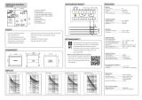
Operate time
Definite time characteristic
The operate time of the overcurrent relay is
measured at a test current equal to 2 x the setting
value of stage I>. The timer is started by closing
switch S1 and stopped by contact 65-66 on
operation of output relay A.
The operation of output relay C is indicated by
lighting of LED L3.
When the relay starts, the yellow indicator I> in
the right bottom corner of the front panel of the
relay module is lit, and when the relay trips it
turns red.
Inverse time characteristic
At inverse time characteristic the operate time of
the relay is measured at two current values (2 x
I> and 10 x I>). The operate times thus received
are compared with the operate times shown in
the current/time curves for the corresponding
inverse time characteristic.
Blocking
Switches 4 and 5 of switchgroup SGB on the PC
board of the relay module are to be set in
position 1 (ON). Switch SGR/1 on the system
panel, too, has to be in position 1.
The blocking function is tested by applying a
control voltage of the auxiliary voltage level to
input 10-11 via switch S2. At first switch S2 is
closed and then the test current is encreased well
above the set start current level.The relay will
start, i.e. L2 is lit, but it must not operate, i.e. L3
remains dark.
Testing of low-set
current stage I>
/