
38452L Rev. 3 Copyright 1995 Zebra Technologies Corporation. All rights reserved.
Zebra S-Series
Maintenance Manual
Volume 1: General Maintenance
Zebra Technologies Corporation
333 Corporate Woods Parkway
Vernon Hills, IL, USA 60061-3109
Telephone: +1 (847) 634-6700
Fax: +1 (847) 913-8766
Zebra Technologies Europe Limited
Zebra House
The Valley Centre, Gordan Road
High Wycombe, Buckinghamshire
HP13 6EQ, UK
Telephone: +44 (0) 1494 472872
Fax: +44 (0) 1494 450103

R

333 Corporate Woods Parkway
Vernon Hills, Illinois, USA 60061-3109
ATTN: Technical Training
FAX Number: +1 (847) 913-8766
Maintenance Manual
(Volume 1, Rev. 3)
Registration Form
To receive Maintenance Manual revisions and updates,
complete this form and fax or mail it to Zebra Technologies
at the fax number or address shown below.
Company __________________________________________
Address ____________________________________________
City________________________________________________
State, Zip___________________________________________
Phone # (_______) __________________________________
Contact: ___________________________________________
Zebra S-Series Printer

R

This manual contains proprietary information of Zebra Technologies Corporation. It is intended solely for the infor-
mation and use of parties operating and maintaining the equipment described herein. Such proprietary information
may not be used, reproduced, or disclosed to any other parties for any other purpose without the expressed written
permission of Zebra Technologies Corporation.
Continuous improvement of products is a policy of Zebra Technologies Corporation. All specifications and signs are
subject to change without notice.
Note: This equipment has been tested and found to comply with the limits for a Class A digital Device, pursuant to
Part 15 of the FCC Rules. These limits are designed to provide reasonable protection against harmful interference
when the equipment is operated in a commercial environment. This equipment generates, uses and can radiate radio
frequency energy and, if not installed and used in accordance with the instructions manual, may cause harmful inter-
ference to radio communications. Operation of this equipment in a residential area is likely to cause harmful interfer-
ence in which case the user will be required to correct the interference at his own expense.
In order to insure compliance, this printer must be used with a Shielded Power Cord and Shielded Communication
Cables.
“The user is cautioned that any changes or modifications not expressly approved by Zebra Technologies Corporation
could void the user’s authority to operate the equipment.”
This digital apparatus does not exceed the Class A limits for radio noise emissions from digital apparatus as set out
in the radio interference regulations of the Canadian Department of Communications.
Zebra Technologies Corporation takes steps to assure that its published Engineering specifications and Manuals are
correct; however, errors do occur. Zebra Technologies Corporation has been advised of the possibility of such dam-
ages. Because some states do not allow the exclusion or limitation of liability for consequential or incidental dam-
ages, the above limitation may not apply to you.
The copyrights in this manual and the label printer described therein are owned by Zebra Technologies Corporation.
All rights are reserved. Unauthorized reproduction of this manual or the software in the label printer may result in
imprisonment of up to one year and fines of up to $10,000 (17 U.S.C.506). Copyright violators may be subject to
civil liability.
BAR-ONE
®
, SCAN-ONE
®
, TRACK-ONE
®
, Zebra
®
, ZPL
®
, and ZPL II
®
are registered
trademarks and WEDGE-ONE™ isa trademark of Zebra Technologies Corporation.
Centronics
®
is a registered trademark of Genicom Corporation.
IBM
®
is a registered trademark of IBM Corporation.
Windows™ is a trademark of Microsoft Corporation.
© Zebra Technologies Corporation. All rights reserved.
38452L Rev. 3 i

R
ii 38452L Rev. 3

........... i
THE ZEBRA S-SERIES SYSTEM
Printer Specifications .....................1-1
Media Handling ......................1-1
Printing Considerations ..................1-2
Media Considerations ................... 1-2
Ribbon Considerations ..................1-3
Zebra Programming Language II (ZPL II
®
) ....... 1-3
Bar Codes .........................1-3
Standard Printer Fonts ...................1-4
Physical Size .......................1-5
Electrical Requirements ..................1-6
Cable Requirements ....................1-6
115 VAC Applications ..................1-6
230 VAC Applications ..................1-6
Environmental Operating Range .............1-6
Communication Specifications ................1-7
Serial Data Communications Overview ..........1-7
Parallel Data Communications Overview .........1-9
GETTING READY TO PRINT
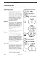
Controls and Indicators ....................2-2
Front Panel Controls ................... 2-2
Front Panel LEDs .....................2-3
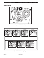
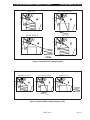
Media Loading ........................2-4
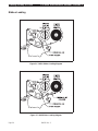
Ribbon Loading ........................2-6
Media Calibration .......................2-7
Adjusting the Print Darkness ................. 2-7
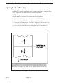
Adjusting the Tear-Off Position ................2-8
Adjusting the Position of the Top of the Label ........2-9
Adjusting the Media Sensor Positions ............ 2-9
Upper Media Sensor .................... 2-9
Lower Media Sensor .................. 2-11
Option Switches ....................... 2-12
Bank 1 .......................... 2-13
Bank 2 .......................... 2-14
38452L Rev. 3 iii

PRINTER DIAGNOSTICS
Power ON Self Test ......................3-1
Printer Self Tests .......................3-1
CANCEL Key Self Test .................. 3-3
PAUSE Key Self Test ................... 3-4
FEED Key Self Test ....................3-5
MODE Key Self Test ................... 3-6
FEED, PAUSE and CANCEL Keys ...........3-6
PAUSE Key and CANCEL Key ............. 3-7
FEED Key and CANCEL Key .............. 3-7
FEED Key and PAUSE Key ...............3-7
Extended Printer Diagnostics .................3-9
PAUSE Key Loopback Test ................3-9
FEED Key Loopback Test ............... 3-10
PREVENTIVE MAINTENANCE
Field Maintenance Functions .................4-1
Tools Required ........................4-1
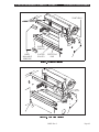
Cleaning the S-Series printer .................4-1
Cleaning the Printhead ....................4-2
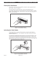
Cleaning the Snap Plate .................... 4-2
Cleaning the Cutter Module ..................4-4
Lubricating the Cutter Module ................4-4
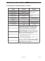
Recommended Preventive Maintenance Schedule ......4-5
CORRECTIVE MAINTENANCE
Tools Required ........................5-2
Test Equipment Required ...................5-2
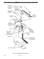
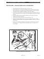
105S Printhead Replacement .................5-3
160S Printhead Replacement .................5-5
Printhead Adjustments ....................5-7
Print Quality Adjustments .................5-7
Printhead Parallelism Adjustment .............5-8
Wear Plate Position Adjustment ..............5-9
Printhead Position Adjustment ............. 5-10
Printhead Pressure Adjustment ............. 5-11
Strip Plate Adjustment ................. 5-12
Printhead Voltage Adjustment ................ 5-12
Adjustment Procedure .................. 5-13
Media Sensor Position Adjustment ............. 5-15
Reflective Sensor Adjustment ................ 5-17
Media Sensor and Ribbon Sensor Sensitivity Adjustment . 5-17
Take Label Sensor Alignment ................ 5-19
iv 38452L Rev. 3

Media Tracking Adjustments ................ 5-20
Rewind Mode ...................... 5-20
Peel-Off Mode ...................... 5-21
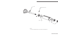
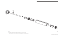
Spindle Adjustment and Maintenance ........... 5-22
Tension Measurement Procedure ............ 5-22
Spindle Tension Adjustment .............. 5-22
Removing the Adapter Board ................ 5-24
Installing the Adapter Board ................ 5-24
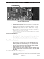
Removing the Main Logic and Power Supply Boards . . . 5-24
Installing the Main Logic and Power Supply Boards .... 5-28
EPROM Software Installation ................ 5-29
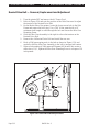
Main Drive Belt — Removal, Replacement & Adjustment . 5-31
Rewind Drive Belt — Removal, Replacement & Adjustment 5-32
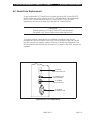
AC Power Fuse Replacement ................ 5-33
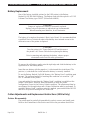
Battery Replacement .................... 5-34
Cutter Adjustments and Replacement Instructiions ..... 5-34
Internal Access ..................... 5-35
Cutter Motor Removal and Installation ......... 5-35
Cutter Mechanical Assembly Removal and Installation 5-37
Drive Link Assembly Installation ............ 5-38
Cutter Circuit Board Removal and Installation ..... 5-38
Optical Sensor Removal and Installation ........ 5-39
Lower Drive Arm Mechanical Alignment ....... 5-39
Upper Drive Arm Alignment .............. 5-40
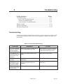
TROUBLESHOOTING
Troubleshooting ........................ 6-1
Power-ON Troubleshooting ................6-1
General Troubleshooting .................6-2
Cutter Module Troubleshooting ..............6-4
Sample Labels .........................6-5
Factory Assistance ..................... 6-11
Returning Equipment .................... 6-11
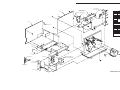
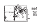
105S and 160S MECHANICAL DRAWINGS and PARTS LISTS
Mechanical Parts and Assemblies ...............7-1
105Se MECHANICAL DRAWINGS and PARTS LISTS
Mechanical Parts and Assemblies ...............8-1
38452L Rev. 3 v

R
vi 38452L Rev. 3

1 The Zebra S-Series System
In this section... Page
Printer Specifications .....................................................................1-1
Media Handling .........................................................................1-1
Printing Considerations............................................................1-2
Media Considerations...............................................................1-2
Ribbon Considerations .............................................................1-3
Zebra Programming Language II (ZPL II
®
).........................1-3
Bar Codes ...................................................................................1-3
Standard Printer Fonts..............................................................1-4
Physical Size..............................................................................1-5
Electrical Requirements ...........................................................1-6
Cable Requirements..................................................................1-6
115 VAC Applications..............................................................1-6
230 VAC Applications..............................................................1-6
Environmental Operating Range ............................................1-6
Communication Specifications .....................................................1-7
Serial Data Communications Overview.................................1-7
Parallel Data Communications Overview .............................1-9
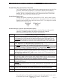
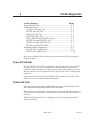
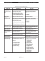
Printer Specifications
Media Handling
• Tear-Off mode: Labels are produced in strips.
• Rewind mode: Requires Media Rewind option. Labels are rewound
internally onto a 3"-inner-diameter cardboard core.
• Peel-Off mode: Requires Peel-Off option or Media Rewind option.
Labels are dispensed and peeled from the liner. The
liner can be rewound directly onto the spindle using
the “J” Hook or onto a 3"-inner-diameter cardboard core.
• Cutter mode Requires Cutter Module option (105Se only). Media is cut
after printing; under software control.
38452L Rev. 3 Page 1-1

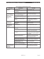
Printing Considerations
Specification 105
S
/105
Se
160
S
Resolution (thermal transfer
or direct thermal)
203 dots per inch
(8 dots per mm)
Optional
152 dots per inch
(6 dots per mm)
Optional
300 dots per inch
(12 dots per mm)
203 dots per inch
(8 dots per mm)
Dot size (square) 0.00492"
(0.125 mm)
0.00656"
(0.167 mm)
0.0033" x 0.0039"
(0.083 x 0.100 mm)
0.00492"
(0.125 mm)
Maximum print width 4.09" (104 mm) 4.09" (104 mm) 4.09" (104 mm) 6.30" (160 mm)
Maximum
print length
Standard 512 KB
memory
15" (381 mm) 26" (660 mm) N/A 9.5" (241mm)
With 1 MG memory 39" (991 mm) 39" (991 mm) 18" (457 mm) 25" (635 mm)
Bar code modulus (“X”) dimension 5 mil to 50 mil 6.6 mil to 66 mil 3.33 mil to 33.3 mil 5 mil to 50 mil
Programmable constant
printing speeds
2" (51 mm), 3" (76 mm), 4" (102 mm), 5" (127 mm), or 6" (152 mm) per second.
The 105S and 105Se with optional 300 dots/inch resolution support
2.4" (61 mm), 3" (76 mm), and 4" (102 mm) per second.
Thin film printhead with Energy Control
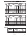
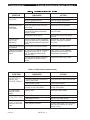
Media Considerations
Media Specifications 105
S
/105
Se
160
S
Total media width Maximum 4.5" 114.3 mm 7.2" 182.9 mm
Minimum 0.75" 19.05 mm 2.0" 50.8 mm
Label length
Maximum 39" (991 mm) 25" (635 mm)
Minimum
Tear-Off 0.63" 16.00 mm 0.63" 16.00 mm
Peel-Off 0.50" 12.8 mm 0.50" 12.8 mm
Rewind 0.50" 12.8 mm 0.50" 12.8 mm
Cutter 1.25" 31.75 mm N/A N/A
Total thickness
(includes liner)
Maximum
(Printhead
position may need adjustment
if thickness is above 0.01")
0.012" 0.304 mm 0.012" 0.304 mm
Minimum 0.0023" 0.058 mm 0.0023" 0.058 mm
Core size 3.0" 76.2 mm 3.0" 76.2 mm
Maximum roll diameter 8.0" 203 mm 8.0" 203 mm
Interlabel gap
(0.115"/3 mm preferred)
0.079" -
0.157"
2 mm - 4 mm 0.079" -
0.157"
2 mm - 4 mm
Black mark
sensing
Minimum mark length
(thickness)
.118” 3 mm .118” 3 mm
Minimum mark width
(extending in from the liner
or tag stock edge)
.393” 10 mm .393” 10 mm
Maximum internal fanfold media
pack size (L x W x H)
8.0" x 4.5"
x 6.2"
203 x 114
x 158 mm
8.0" x 7.2"
x 6.2"
203 x 183
x 158 mm
The
S
-Series System
S
-Series Maintenance Manual: Volume 1
Page 1-2 38452L Rev. 3

Zebra Programming Language II (ZPL II
®
)
Bar Codes
The following bar codes are available:
Ribbon Considerations
Ribbon Specifications 105
S
/105
Se
160
S
Ribbon width
To protect the printhead from wear, Zebra recommends using
ribbon at least as wide as the media you are using.
Maximum 4.5" 114 mm 6.89" 175 mm
Minimum 0.75" 19 mm 2.0" 50.8 mm
Standard
lengths
2:1 media to ribbon roll ratio 984 ft 300 m 984 ft 300 m
3:1 media to ribbon roll ratio 1476 ft 450 m 1476 ft 450 m
Roll size Inner diameter of core 1.0" 25.4 mm 1.0" 25.4 mm
Outside diameter of full ribbon roll 3.2" 81.2 mm 3.2" 81.2 mm
• Downloadable graphics
(with data compression)
• Bit image data transfer and printing,
including mixing of text and graphics
• Format inversion
• Mirror image printing
• Four-position field rotation
(0, 90, 180, 270 degrees)
• Slew command
• Programmable quantity with print pause
• Communicates in printable ASCII
characters
• Controlled via mainframe, mini, PC,
Zebra-Mate or other data-entry device
• Serialized fields
• In-spec OCR-A and OCR-B
• UPC/EAN at nominal 100% magnification
(6 dot/mm and 12 dot/mm printheads only)
• Code 11, Code 49, Code 93
• Code 39 (Supports ratios of 2:1, 3:1, 5:2,
and 7:3)
• Code 128 (Supports serialization in subsets B
and C and UCC Case C Codes)
• CODABAR (Supports ratios of 2:1, 3:1 and
5:2)
• Interleaved 2 of 5 (Supports ratios of 2:1,
3:1 and 5:2; also supports Modulus 10
Check Digit)
• Industrial 2 of 5, Standard 2 of 5
• Plessey
• MSI
• CODABLOCK and MAXICODE
• E/EAN-8, E/EAN-13, EAN EXTENSIONS
• UPC-A, UPC-E, UPC EXTENSIONS
• PDF 417 and POSTNET
• Data Matrix
S
-Series Maintenance Manual: Volume 1 The
S
-Series System
38452L Rev. 3 Page 1-3

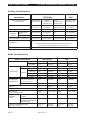
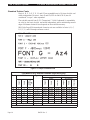
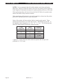
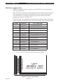
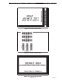
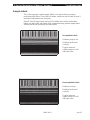
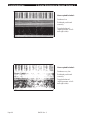
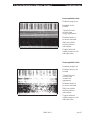
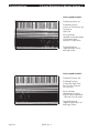
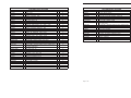
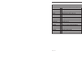
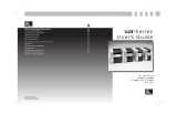
Standard Printer Fonts
Fonts A, B, C, D, E, F, G, H, and GS are expandable up to 10 times, height- and
width-independent. However, fonts E and H (OCR-A and OCR-B) are not
considered “in-spec” when expanded.
The scalable smooth font Ø (CG Triumvirate™ Bold Condensed) is expandable
on a dot-by-dot basis, height- and-width independent, while maintaining smooth
edges. Maximum character size depends on the available memory.
IBM Code Page 850 international character sets are available in fonts A, B, C,
D, E, F, G, and Ø through software control.
Font Matrices for 6 dots/mm Printhead (105
S
/105
Se
only)
Font Matrix Type* Character Size
Inches Millimeters
Height
Width
Inter-
character
gap
Height
Width
Char./inch
Height
Width
Char./mm
A 9 5 1 U-L-D 0.059 0.039 25.40 1.50 1.00 1.00
B 11 7 2 U 0.072 0.059 16.93 1.83 1.50 0.67
C, D 18 10 2 U-L-D 0.118 0.079 12.70 3.00 2.00 0.50
E 21 10 3 OCR-B 0.138 0.085 11.72 3.50 2.17 0.46
F 26 13 3 U-L-D 0.171 0.105 9.53 4.33 2.67 0.38
G 60 40 8 U-L-D 0.394 0.315 3.18 10.00 8.00 0.13
H 17 11 4 OCR-A 0.112 0.098 10.16 2.83 2.50 0.40
GS 24 24 0 SYMBOL 0.157 0.157 6.35 4.00 4.00 0.25
Ø Default: 15 x 12 U-L-D Scalable
* U = Uppercase, L = Lowercase, D = Descenders
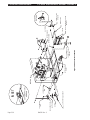
Figure 1.1 Sample of Default Fonts
The
S
-Series System
S
-Series Maintenance Manual: Volume 1
Page 1-4 38452L Rev. 3

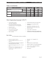
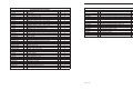
Font Matrices for 8 dots/mm Printhead (105
S
, 105
Se
and 160
S
)
Font Matrix Type* Character Size
Inches Millimeters
Height
Width
Inter-
character
gap
Height
Width
Char./inch
Height
Width
Char./mm
A 9 5 1 U-L-D 0.044 0.029 33.90 1.13 0.75 1.33
B 11 7 2 U 0.054 0.044 22.60 1.38 1.13 0.89
C, D 18 10 2 U-L-D 0.088 0.059 16.95 2.25 1.50 0.67
E 28 15 5 OCR-B 0.138 0.098 10.17 3.50 2.50 0.40
F 26 13 3 U-L-D 0.128 0.079 12.71 3.25 2.00 0.50
G 60 40 8 U-L-D 0.295 0.236 4.24 7.50 6.00 0.17
H 21 13 6 OCR-A 0.103 0.093 10.71 2.63 2.38 0.42
GS 24 24 0 SYMBOL 0.118 0.118 8.48 3.00 3.00 0.33
Ø Default: 15 x 12 U-L-D Scalable
* U = Uppercase, L = Lowercase, D = Descenders
Font Matrices for 12 dots/mm Printhead (105
S
/105
Se
)
Font Matrix Type* Character Size
Inches Millimeters
Height
Width
Inter-
character
gap
Height
Width
Char./inch
Height
Width
Char./mm
A 9 5 1 U-L-D 0.029 0.016 50.80 0.73 0.40 2.00
B 11 7 2 U 0.036 0.023 33.86 0.91 0.58 1.34
C, D 18 10 2 U-L-D 0.059 0.033 25.40 1.49 0.83 1.00
E 42 20 6 OCR-B 0.138 0.066 23.44 3.50 1.67 0.92
F 26 13 3 U-L-D 0.185 0.042 19.06 2.15 1.06 0.76
G 60 40 8 U-L-D 0.198 0.132 6.36 5.02 3.35 0.26
H 34 22 8 OCR-A 0.112 0.072 20.32 2.84 1.82 0.80
GS 24 24 0 SYMBOL 0.079 0.079 12.70 2.00 2.00 0.50
Ø Default: 15 x 12 U-L-D Scalable
* U = Uppercase, L = Lowercase, D = Descenders
Physical Size
Physical
Characteristics 105
S
/105
Se
160S
Height 15.4" 391 mm 15.4" 391 mm
Width 10.5" 267 mm 13.1" 333 mm
Depth 18.9" 480 mm 18.9" 480 mm
Weight (without options) 43 lbs. 19.5 kg 55 lbs. 24.9 kg
S
-Series Maintenance Manual: Volume 1 The
S
-Series System
38452L Rev. 3 Page 1-5

Electrical Requirements
• 115 VAC +15%/−20%or230VAC+15%/−15%, 48-62 Hz
• 5Amps@115V,3Amps@230V
• UL 1950 Listed - Certified to CAN/CSA-C22.2 No. 950-M89
• Classified to IEC 950 and Complies with FCC and Canadian DOC class “A” rules
• Carries the CE mark of compliance
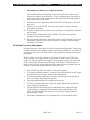
Cable Requirements
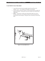
The AC Power Cord has a three-prong female connector on one end. This
connector must be plugged into the mating connector at the rear of the S-Series
printer.
115 VAC Applications
A Standard US-style, three-prong grounded male plug is attached to the other
end of the AC Power Cord. This connector must be plugged into a nearby
electrical outlet.
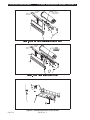
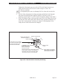
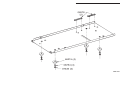
230 VAC Applications
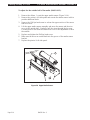
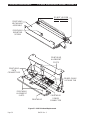
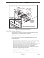
An AC Power Cord may or may not be included with the printer. For those
locations that cannot use either of the three power cords listed below, a proper
grounded AC Power Cord must be obtained and installed by the user (See Figure
2.2). The cable must then be plugged into a nearby electrical outlet.
Part Number AC Power Cable Description
44618 Detachable Power Cord (US Standard 3-prong plug - 115 VAC)
44629 Detachable Power Cord (Continental Europe 3-prong plug - 230 VAC)
44637 Detachable Power Cord (British 3-prong plug - 230 VAC)
Environmental Ranges
Temperature
Operating +41°F to +104°F (+5°C to +40°C)
Storage -40°F to +158°F (-40°C to +70°C)
Non-condensing
relative humidity
Operating 20% to 85%
Storage 20% to 85%
The
S
-Series System
S
-Series Maintenance Manual: Volume 1
Page 1-6 38452L Rev. 3

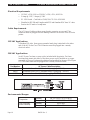
Communication Specifications
Both serial and parallel data communication interfaces are available for the
S-Series printers. The S-Series printer sends and receives standard ASCII
(American Standard Code for Information Interchange) data characters.
With ZPL II
®
, the Error Detection Protocol feature provides virtually error-free
communications. Refer to the user’s guide for further information.
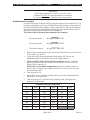
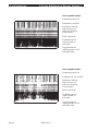
Serial Data Communications Overview
The S-Series printers have a Data Terminal Equipment (DTE) port that supports
RS-232 serial data communications. The RS-232 interface has a standard 25-pin
DB25-S connector located at the rear of the printer. For all RS-232 input and
output signals, the S-Series printer follows the EIA RS-232 and CCITT V.24
specifications for signal levels.
The baud rate, number of data bits, and parity are user-selectable via DIP
switches at the rear of the printer. Parity only applies to data transmitted by the
printer. The parity associated with received data is ignored. Further information
on the settings of these switches is contained in the printer’s user’s guide.
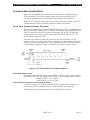
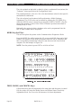
Serial Data Signal Levels
Serial data signals are defined as either MARK or SPACE, while control signals
are either ON or OFF. The output levels for the S-Series printers are as follows:
MARK or OFF = - 7 to - 10 Volts
SPACE or ON = +7 to +10 Volts
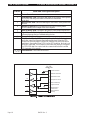
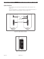
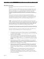
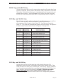
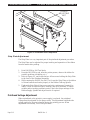
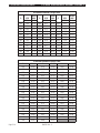
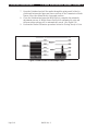
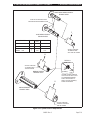
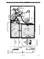
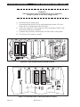
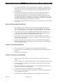
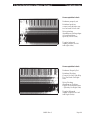
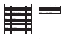
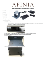
Serial Interface Connector Pinout and Description
A DB25-S connector is located at the rear of the Zebra S-Series printer and
provides serial data communications to a host using RS-232 signaling.
The pinouts and signal descriptions for the DTE port are as follows:
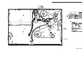
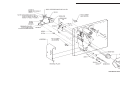
Figure 1.3 RS-232 Signal/ASCII Code Data Conditions
S
-Series Maintenance Manual: Volume 1 The
S
-Series System
38452L Rev. 3 Page 1-7

Pin No. Serial Data Port Signal Description
1 Frame Ground
2 Transmit Data: TXD is the serial data output of the Zebra S-Series printer.
It is on this lead that printer status information is transmitted
to the host.
3 Receive Data: RXD is the serial data input to the Zebra S-Series printer from
the host.
4 Request To Send: RTS is an output from the Zebra S-Series printer.
It is a constantly active output to the host computer.
6 Data Set Ready: DSR is an input to the Zebra S-Series printer from the host.
7 Signal Ground: Tied to logic ground. This lead serves as the voltage
reference between the two communicating devices.
9 Reserved: For Future Use.
20 Data Terminal Ready: DTR is an output from the Zebra S-Series printer
and is the control line between the printer and the host. When the DTR
control line from the printer is in the ON condition, the host is allowed to
send data to the printer. When DTR is in the OFF condition, the host is not
allowed to send data. This condition occurs when the printer is configured
for DTR/DSR data flow control and the communication buffer is within
512 characters of its capacity.
5, 8, 10-19,
21-25
Unterminated: These leads are not used.
RS-232
J7
20
1 Amp
F
4
9
7
6
4
+5 V
Data Terminal
Ready
Data Set Ready
Signal Ground
Request To Send
3
2
1
Receive
Transmit
Frame Ground
Reserved for
Future Use
MAX232
8
7
13
14
10
9
12
11
COMM PORT
RS-23 2
RS-23 2
The
S
-Series System
S
-Series Maintenance Manual: Volume 1
Page 1-8 38452L Rev. 3

Parallel Data Communications Overview
The S-Series printer may have a parallel data communications port instead of the
previously mentioned serial data port. The Parallel Interface has a standard
36-pin connector located at the rear of the printer. In this data communication
method, the bits of data which make up each character are sent all at one time
over several wires in the cable, one bit per wire.
Parallel Data Signal Levels
Parallel data signals are defined as either HIGH or LOW, while Control Signals
are either Active or Inactive. The distinction is due to the fact that some Control
Signals are active HIGH while others are active LOW. The voltage levels which
represent these conditions are:
Data Signal Voltage Level
HIGH +5 VDC
LOW 00 VDC
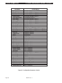
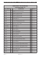
Parallel Interface Connector Pinout and Description
The following chart provides a description of each of the pins in the parallel
connector. A standard parallel data cable will provide the required
interconnection between the host and the S-Series printer.
For an illustration of the parallel communication data and control circuits, refer
to the Main Logic Board Schematic in Volume 2 ( Part # 38453L).
Pin No. Parallel Data Port Signal Description
1 The
STROBE printer input has internal 3.3 k pull-up resistors to 5V (I
OL
= 1.5mA) and is
designed to receive a signal driven open collector V
OL
<= 0.8V. This pin is a signal from the
host computer. Its LOW going edge will latch the data at the eight DATA inputs. Data is
non-transparently latched so as to avoid hold time requirements on the DATA signals. The
STROBE input is debounced to require an active width greater than 0.5 µsec before data is
latched.
2 - 9 DATA inputs have TTL input characteristics with internal 3.3 k
pullups and represent
1 TTL unit load or less. The DATA inputs are positive logic with a HIGH voltage level
corresponding to a logic 1. Pin 2 through Pin 9 = D0 through D7 respectively.
10 The
ACK output is a 12 microsecond active LOW pulse indicating that the printer is ready to
accept data. The active LOW state precedes BUSY by 7 microseconds.
ACK is driven open
collector with a 3.3 k
internal pull-up. The output sinks 7 mA to a V
OL
<= 0.4V.
11 The BUSY output is active HIGH whenever the printer cannot accept data due to any
normal or abnormal condition, including Buffer Overflow, Head Open, Over Temperature,
and Media Error conditions. BUSY is driven open collector with a 3.3 k
internal pull-up.
The output sinks 7 mA to a V
OL
<= 0.4V.
12 The PAPER OUT signal is active HIGH whenever the printer is out of media or ribbon.
13 The SELECT signal function is determined by an additional configuration option which
becomes active when the port is present. In the default condition, SELECT is active HIGH
whenever the parallel port is powered up and the parallel port is enabled. In the non-default
condition, SELECT will go active LOW whenever the printer is printing.
18 +5 VDC Supply provides an output of +5 VDC at a maximum current rating of 50 mA.
(Internal Fuse Protected)
32 The
ERROR Output (Pin 15) is active LOW whenever any error condition is present.
ERROR is driven open collector with a 3.0 k internal pull-up. The output sinks 7 mA to a
V
OL
<= 0.4V.
35 +5 VDC Pull-Up provides an output of +5 VDC through an internal 3.0 k
resistor.
16, 17, 19 -
30, 33
SIGNAL GROUNDS are the Logic Grounds and Returns for all Input and Output signals.
14, 15, 31,
34, 36
NOT USED - These leads should be left unconnected.
S
-Series Maintenance Manual: Volume 1 The
S
-Series System
38452L Rev. 3 Page 1-9

R
The
S
-Series System
S
-Series Maintenance Manual: Volume 1
Page 1-10 38452L Rev. 3
Page is loading ...
Page is loading ...
Page is loading ...
Page is loading ...
Page is loading ...
Page is loading ...
Page is loading ...
Page is loading ...
Page is loading ...
Page is loading ...
Page is loading ...
Page is loading ...
Page is loading ...
Page is loading ...
Page is loading ...
Page is loading ...
Page is loading ...
Page is loading ...
Page is loading ...
Page is loading ...
Page is loading ...
Page is loading ...
Page is loading ...
Page is loading ...
Page is loading ...
Page is loading ...
Page is loading ...
Page is loading ...
Page is loading ...
Page is loading ...
Page is loading ...
Page is loading ...
Page is loading ...
Page is loading ...
Page is loading ...
Page is loading ...
Page is loading ...
Page is loading ...
Page is loading ...
Page is loading ...
Page is loading ...
Page is loading ...
Page is loading ...
Page is loading ...
Page is loading ...
Page is loading ...
Page is loading ...
Page is loading ...
Page is loading ...
Page is loading ...
Page is loading ...
Page is loading ...
Page is loading ...
Page is loading ...
Page is loading ...
Page is loading ...
Page is loading ...
Page is loading ...
Page is loading ...
Page is loading ...
Page is loading ...
Page is loading ...
Page is loading ...
Page is loading ...
Page is loading ...
Page is loading ...
Page is loading ...
Page is loading ...
Page is loading ...
Page is loading ...
Page is loading ...
Page is loading ...
Page is loading ...
Page is loading ...
Page is loading ...
Page is loading ...
Page is loading ...
Page is loading ...
Page is loading ...
Page is loading ...
Page is loading ...
Page is loading ...
Page is loading ...
Page is loading ...
Page is loading ...
Page is loading ...
Page is loading ...
Page is loading ...
Page is loading ...
Page is loading ...
Page is loading ...
Page is loading ...
Page is loading ...
Page is loading ...
Page is loading ...
Page is loading ...
Page is loading ...
Page is loading ...
Page is loading ...
Page is loading ...
Page is loading ...
Page is loading ...
Page is loading ...
Page is loading ...
Page is loading ...
Page is loading ...
Page is loading ...
Page is loading ...
Page is loading ...
Page is loading ...
Page is loading ...
Page is loading ...
Page is loading ...
Page is loading ...
Page is loading ...
Page is loading ...
Page is loading ...
Page is loading ...
Page is loading ...
Page is loading ...
Page is loading ...
Page is loading ...
Page is loading ...
Page is loading ...
Page is loading ...
Page is loading ...
Page is loading ...
Page is loading ...
Page is loading ...
Page is loading ...
Page is loading ...
Page is loading ...
Page is loading ...
Page is loading ...
Page is loading ...
Page is loading ...
Page is loading ...
Page is loading ...
Page is loading ...
Page is loading ...
Page is loading ...
Page is loading ...
Page is loading ...
Page is loading ...
Page is loading ...
Page is loading ...
Page is loading ...
Page is loading ...
Page is loading ...
Page is loading ...
Page is loading ...
Page is loading ...
Page is loading ...
Page is loading ...
-
 1
1
-
 2
2
-
 3
3
-
 4
4
-
 5
5
-
 6
6
-
 7
7
-
 8
8
-
 9
9
-
 10
10
-
 11
11
-
 12
12
-
 13
13
-
 14
14
-
 15
15
-
 16
16
-
 17
17
-
 18
18
-
 19
19
-
 20
20
-
 21
21
-
 22
22
-
 23
23
-
 24
24
-
 25
25
-
 26
26
-
 27
27
-
 28
28
-
 29
29
-
 30
30
-
 31
31
-
 32
32
-
 33
33
-
 34
34
-
 35
35
-
 36
36
-
 37
37
-
 38
38
-
 39
39
-
 40
40
-
 41
41
-
 42
42
-
 43
43
-
 44
44
-
 45
45
-
 46
46
-
 47
47
-
 48
48
-
 49
49
-
 50
50
-
 51
51
-
 52
52
-
 53
53
-
 54
54
-
 55
55
-
 56
56
-
 57
57
-
 58
58
-
 59
59
-
 60
60
-
 61
61
-
 62
62
-
 63
63
-
 64
64
-
 65
65
-
 66
66
-
 67
67
-
 68
68
-
 69
69
-
 70
70
-
 71
71
-
 72
72
-
 73
73
-
 74
74
-
 75
75
-
 76
76
-
 77
77
-
 78
78
-
 79
79
-
 80
80
-
 81
81
-
 82
82
-
 83
83
-
 84
84
-
 85
85
-
 86
86
-
 87
87
-
 88
88
-
 89
89
-
 90
90
-
 91
91
-
 92
92
-
 93
93
-
 94
94
-
 95
95
-
 96
96
-
 97
97
-
 98
98
-
 99
99
-
 100
100
-
 101
101
-
 102
102
-
 103
103
-
 104
104
-
 105
105
-
 106
106
-
 107
107
-
 108
108
-
 109
109
-
 110
110
-
 111
111
-
 112
112
-
 113
113
-
 114
114
-
 115
115
-
 116
116
-
 117
117
-
 118
118
-
 119
119
-
 120
120
-
 121
121
-
 122
122
-
 123
123
-
 124
124
-
 125
125
-
 126
126
-
 127
127
-
 128
128
-
 129
129
-
 130
130
-
 131
131
-
 132
132
-
 133
133
-
 134
134
-
 135
135
-
 136
136
-
 137
137
-
 138
138
-
 139
139
-
 140
140
-
 141
141
-
 142
142
-
 143
143
-
 144
144
-
 145
145
-
 146
146
-
 147
147
-
 148
148
-
 149
149
-
 150
150
-
 151
151
-
 152
152
-
 153
153
-
 154
154
-
 155
155
-
 156
156
-
 157
157
-
 158
158
-
 159
159
-
 160
160
-
 161
161
-
 162
162
-
 163
163
-
 164
164
-
 165
165
-
 166
166
-
 167
167
-
 168
168
-
 169
169
-
 170
170
-
 171
171
-
 172
172
-
 173
173
-
 174
174


Ask a question and I''ll find the answer in the document
Finding information in a document is now easier with AI
Related papers
-
 Zebra Technologies 160S User manual
-
 Zebra Technologies Stripe User manual
-
Zebra 105 SL Installation guide
-
 Zebra Technologies XiII-Series User manual
-
Zebra ZPL Owner's manual
-
Zebra Technologies Zebra Z4000 User manual
-
-
 Zebra Technologies S600 User manual
-
 Zebra Technologies ZM400 User manual
-


Other documents
-
 Zebra Technologies 170PAX2TM User manual
-
Brady MVPplus Quick Reference Manual
-
Altec TTP-343 Quick Installation Manual
-
3M I/O Connector Mounting Options and Hardware Operating instructions
-
CAB A Series User manual
-
 Genicom 90 TM User manual
-
 Afinia L801 Operating Instructions Manual
-
Panduit PTR3E User manual
-
SimTek LT4521 User guide
-
Ortech SL-RGB50M User manual


